Fostex PD-6 User manual

Service Manual
Model
PD-6
DVDLOCATIONRECORDER
<DANGER>
VISIBLE OR INVISIBLE LASER RADIATION WHEN OPEN.
AVOID DIRECT EXPOSURE TO BEAM.
<CAUTION>
•Use of controls or adjustments or performance of procedures
other than those specified herein may result in hazardous
radiation exposure.
• The use of optical instruments with this product will increase
eye hazard.

SAFETY INSTRUCTIONS
Read instructions - All the safety and operating instruc-
tions should be read before the appliance is operated.
Retain instructions - The safety and operating instructions
should be retained for future reference.
Heed warnings - All warnings on the appliance and in the
operating instructions should be adhered to.
Follow instructions - All operating and use instructions
should be followed.
Water and Moisture - The appliance should not be used
near water - for example, near a bathtub, washbowl,
kitchen sink, laundry tub, in a wet basement, or near a
swimming pool, and the like.
Carts and Stands - The appliance should be used only
with a cart or stand that is recommended by the manufac-
turer.
An appliance and cart combination should be moved with
care. Quick stops, excessive force, and uneven surfaces
may cause the appliance and cart combination to over-
turn.
Wall or Ceiling Mounting - The appliance should be
mounted to a wall or ceiling only as recommended by the
manufacturer.
Ventilation - The appliance should be situated so that its
location or position does not interfere with its proper ven-
tilation. For example, the appliance should not be situ-
ated on a bed, sofa, rug, or similar surface that may block
the ventilation openings; or, placed in a built-in installa-
tion, such as a bookcase or cabinet that may impede the
flow of air through the ventilation openings.
Heat - The appliance should be situated away from heat
sources such as radiators, heat registers, stoves, or other
appliances (including amplifiers) that produce heat.
Power Sources - The appliance should be connected to a
power supply only of the type described in the operating
instructions or as marked on the appliance.
Grounding or Polarization - The precautions that should
be taken so that the grounding or polarization means of
an appliance is not defeated.
Power Cord Protection - Power supply cords should be
routed so that they are not likely to be walked on or
pinched by items placed upon or against them, paying
particular attention to cords at plugs, convenience recep-
tacles, and the point where they exit from the appliance.
Cleaning - The appliance should be cleaned only as rec-
ommended by the manufacturer.
Nonuse Periods - The power cord of the appliance should
be unplugged from the outlet when left unused for a long
period of time.
Object and Liquid Entry - Care should be taken so that
objects do not fall and liquids are not spilled into the en-
closure through openings.
Damage requiring Service - The appliance should be ser-
viced by qualified service personnel when:
A.
B.
C.
D.
E.
Servicing - The user should not attempt to service the ap-
pliance beyond that described in the operating instruc-
tions. All other servicing should be referred to qualified
service personnel.
REFER SERVICING TO QUALIFIED SERVICE PERSONNEL.
CAUTION
RISK OF ELECTRIC SHOCK
DO NOT OPEN
CAUTION: TO REDUCE THE RISK OF ELECTRIC SHOCK,
DO NOT REMOVE COVER (OR BACK).
NO USER-SERVICEABLE PARTS INSIDE.
TO PREVENT ELECTRIC SHOCK, MATCH
WIDE BLADE OF PLUG TO WIDE SLOT,
FULLY INSERT.
POUR ÉVITER LES CHOCS ÉLECTRIQUES,
INTRODUIRE LA LAME LA PLUS LARGE DE
LA FICHE DANS LA BORNE CORRE-
SPONDANTE DE LA PRISE ET POUSSER
JUSQU' AU FOND.
CAUTION:
ATTENTION:
The exclamation point within an equilateral
triangle is intended to alert the user to the
presence of important operating and mainte-
nance (servicing) instructions in the litera-
ture accompanying the appliance.
The lightening flash with arrowhead symbol,
within an equilateral triangle, is intended to
alert the user to the presence of uninsulated
“dangerous voltage” within the product's
enclosure that may be of sufficient magni-
tude to constitute a risk of electric shock to
persons.
“WARNING”
“TO REDUCE THE RISK OF FIRE OR ELECTRIC SHOCK,
DO NOT EXPOSE THIS APPLIANCE TO RAIN OR MOIS-
TURE.”
1.
2.
3.
4.
5.
6.
7.
8.
The power supply cord or the plug has been damaged;
or
Objects have fallen, or liquid has been spilled into the
appliance; or
The appliance has been exposed to rain; or
The appliance does not appear to operate normally or
exhibits a marked changed in performance; or
The appliance has been dropped, or the enclosure
damaged.
9.
10.
11.
12.
13.
14.
15.
16.
17.

3
PD-6 Service Manual
Parts marked with this sign are safety critical components. They must always be replaced with identical
components. Refer to the Fostex Parts List and ensure exact replacement.
CAUTION
TABLE OF CONTENTS
NOTES
*Service menus, exploded view, PCB assembly, parts list and circuit diagrams are given in this manual to assist
the service technician in maintaining the Model PD-6.
* The following accessories are supplied with PD-6 as the standard accessories.
PD-6 owner's manual, English : 8288498000
PD-6 owner's manual, Japanese : 8288499000
PD-6 owner’s manual supplement, 1.01, ENG : 8289602000
PD-6 owner’s manual supplement, 1.01, JPN : 8289603000
PD-6 owner’s manual supplement, 1.02, ENG : 8289604000
PD-6 owner’s manual supplement, 1.02, JPN : 8289605000
Shoulder belt assy : 8260374200
DVD-RAM disk, DRMS-V28R 1P : 8266097000
*Following is the packing material for the Model PD-6.
Carton, inner, PD-6 : 8228753000
Carton, outer, PD-6 : 8228932000
Packing, side, L, PD-6 : 8228477001
Packing, side, R, PD-6 : 8228477002
1.
2.
3.
4.
5.
6.
7.
8.
4
8
11
14
21
22
52
83
SPECIFICATIONS . . . . . . . . . . . . . . . . . . . . . . . . . . . . . . . . . . . . . . . . . . . . . . . . . . . . . . .
CONTROLS, INDICATORS & CONNECTORS . . . . . . . . . . . . . . . . . . . . . . . . . . . . . . . .
SOFTWARE UPDATE . . . . . . . . . . . . . . . . . . . . . . . . . . . . . . . . . . . . . . . . . . . . . . . . . . . .
SERVICE MENUS . . . . . . . . . . . . . . . . . . . . . . . . . . . . . . . . . . . . . . . . . . . . . . . . . . . . . . .
ERROR CODE LIST . . . . . . . . . . . . . . . . . . . . . . . . . . . . . . . . . . . . . . . . . . . . . . . . . . . . . .
EXPLODED VIEW, PCB ASSEMBLY & PARTS LIST . . . . . . . . . . . . . . . . . . . . . . . . . .
CIRCUIT & BLOCK DIAGRAMS . . . . . . . . . . . . . . . . . . . . . . . . . . . . . . . . . . . . . . . . . . .
LOCATION OF IDENTIFICATION / CERTIFICATION LABEL . . . . . . . . . . . . . . . . . .
4
PD-6 Service Manual
1. SPECIFICATIONS
SPECIFICATION UNIT
0 dBu = 0.775 Vr.m.s.
INPUT & OUTPUT
REFERENCE LEVEL -18 dB / -20 dB (default) (Switchable by SETUP mode)
ANALOG INPUT (CH 1 ~ 6)
Connector XLR-3-31 type (Pin 1: GND, Pin 2: HOT, Pin 3: COLD)
Input Impedance 10 kΩor more
LINE
Input Level - 30 ~ + 4 dBu (±5 dB)
Maximum Input Level (REF: -20 dB) + 24 dBu (+ 41 dBu (pre fader))
MIC
Input Level - 60 ~ - 26 dBu (±5 dB)
Maximum Input Level (REF: -20 dB) - 40 dBu (- 23 dBu (pre fader))
ANALOG OUTPUT (TRK 1 ~ 6)
Connector XLR-3-32 type (Pin 1: GND, Pin 2: HOT, Pin 3: COLD)
Load Impedance 10 kΩor more
Standard Output Level + 4 dBu
Maximum Output Level + 24 dBu
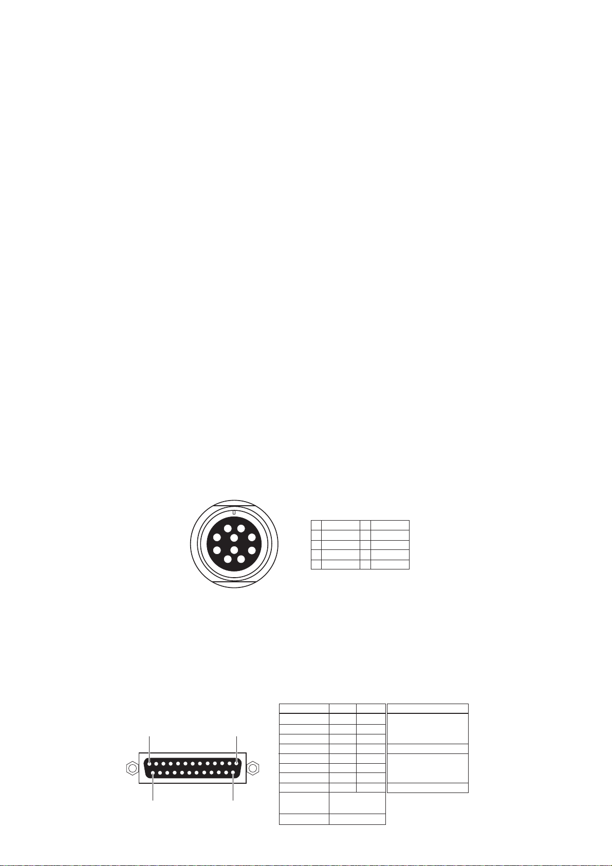
AUX I/O
Connector Hirose RM15TRD-10S, female
Input Balanced audio input for monitoring purpose
Input Impedance 10 kΩor more
Standard Input Level + 4 dBu
Maximum Input Level + 24 dBu
Output Balanced ST BUSS OUT
Load Impedance 10 kΩor more
Standard Output Level + 4 dBu / - 10 dBu / - 60 dBu (switchable)
Maximum Output Level + 24 dBu
DIGITALI/O (CH 1 ~ 6)
Connector D-SUB 25-pin
Format
Input Detect either IEC60958 PART 3 (AES/EBU) or IEC60958
PART 2 (S/PDIF) automatically
Output Either IEC60958 PART 3 (AES/EBU) or IEC60958 PART 2
(S/P DIF) is selectable by SETUP menu
10 3
4
65
12
9
8
7
1
2
3
4
5
L OUT +
L OUT -
R OUT +
R OUT -
R IN +
6
7
8
9
10
R IN -
L IN +
L IN -
GND
GND
1
Signal
Input 1/2
Input 3/4
Input 5/6
Input 7/8
Output 1/2
Output 3/4
Output 5/6
Output 7/8
Frame GND
Open
Hot
1
2
3
4
5
6
7
8
Cold
14
15
16
17
18
19
20
21
10, 12, 13, 22,
23, 24, 25
9, 11
TerminalTreatment
Open
GND
13
1425
5
PD-6 Service Manual
TIME CODE INPUT
Connector XLR-3-31 type (Pin 1: GND, Pin 2: HOT, Pin 3: COLD)
Format SMPTE / EBU
Input Impedance 20 kΩor more
Standard Input Level 2 V p-p
Minimum Input Level 0.25 V p-p
TIME CODE OUTPUT
Connector XLR-3-32 type (Pin 1: GND, Pin 2: HOT, Pin 3: COLD)
Format SMPTE / EBU
Output Impedance 1 kΩor less
Standard Output Level 2 V p-p
Load Impedance 600 Ωor more
VIDEO/WORD INPUT
Connector BNC (Automatically switchable)
Standard Input Level TTL level (with 75 Ωterminate switch)
WORD OUTPUT
Connector BNC
Standard Output Level TTL level
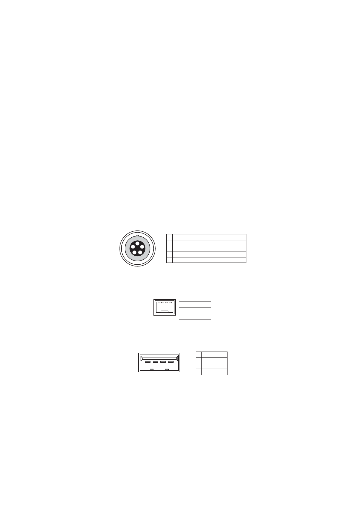
AATON I/O (optional)
Connector LEMO 5-pin connector
Format ASCII I/O & LTC I/O (parallel with TC I/O)
IEEE1394
Format Comply to P1394a Draft 2.0, 4-pin, for PC connection
USB
Connector SeriesA receptacle, for connecting a USB keyboard only
23141
2
3
4
TPB -
TPB +
TPA -
TPA +
PHONES (MONO / MS / SOLO/ PFL/AUX IN /
ST BUS / 1+2 / 1, 3, 5 + 2, 4, 6 / 3, 5 + 4, 6)
Connector ø 6.35 mm stereo phone jack
Load Impedance 32 Ωor more
Maximum Output Level 200 mW at 32 Ω
SPEAKER (with Drip-proof type sheet)
Impedance 4 Ω
Maximum Output Level 720 mW
1
2
3
4
VBUS
D -
D +
GND
2314
1
1
2
3
4
5
GND
LTC OUT
ASCII IN-OUT
AUDIOTAPE (not compatible)
LTC IN
2
3
4
5

6
PD-6 Service Manual
SLATE MIC Switch between 1 kHz reference tone and analog input signal.
It can be used for Input / Master fader adjustment.
SLATETONE Switch between internal microphone and analog input signal.
LIMITER
Attack Time About 20 msec
Release Time About 150 msec
Threshold Full Scale level - 6 / - 12 dB (Selectable by SETUP mode)
Ratio 1 : 5 / 1 :2 3 (Selectable by SETUP mode)
Link MONO / 1-2 CH / 1-6 CH (Selectable by SETUP mode)
PARALLELREMOTE
Connector Mini DIN, 8-pin, female
Pin assignment Comply to PD-2 / PD-4. It functions regardless of PANEL
LOCKkey.Connectingaterminal to GND activatesafunction.
DC 12 V IN
Connector XLR-4-32 type, male
Pin assignment Complyto PD-2. It functions regardless of PANELLOCK key.
DC 12 VOUT (x 2)
Connector Hirose HR10-7R-4S, 4-pin, female
Output DC voltage input to DC 12V IN terminal is output.
34
6
5
2
87
1
1
2
3
4
5
6
7
8
PLAY
STOP
REC
GND
SHIFT
REWIND
VBATT*
FF
SHIFT + STOP
SHIFT + REC
SHIFT + REW
SHIFT + FF
CUE
PAUSE
SKIP/CURSOR
SKIP/CURSOR
DC + 12 ~ 18V, MAX 500 mA.
DC voltage is output regardless
of PD-6 POWER ON/OFF condition.
*
3
4
2
1
1
2
3
4
GND
NC
NC
DC +12 ~ 18V
RECORD & PLAYBACK
MEDIUM ATAPI (E-IDE) standard 8 cm DVD-RAM drive / disk
RESOLUTION / SAMPLING FREQUENCY 16 bits: 44.1 / 48 kHz
24 bits: 44.1 / 48 / 88.2 / 96 kHz
TRACK MODE
2TRK 44.1 / 48 / 88.2 / 96 kHz
4TRK 44.1 / 48 kHz
5TRK 44.1 / 48 kHz
6TRK 44.1 / 48 kHz
2 + 4TRK 44.1 / 48 kHz
1 + 5TRK 44.1 / 48 kHz
RECORDING TIME (on one side of 8 cm DVD-RAM
disk (about 1.2GB capacity after UDF formatting))
16 bits, 2TRK, 44.1 / 48 kHz About 118 / 108 minutes
24 bits, 2TRK, 44.1 / 48 / 88.2 / 96 kHz About 78 / 72 / 39 / 36 minutes
24 bits, 6TRK, 44.1 / 48 kHz About 26 / 24 minutes
1
2
3
4
GND
NC
NC
DC OUT*
3
42
1DC voltage input to DC IN via protection
components are output regardless of
PD-6 POWER ON/OFF condition.
*

7
PD-6 Service Manual
OPERATION
LOCATE MEMORY Cue Point Chunk: 100
EXT / INT BATT key
DISPLAY
Black & White LCD (128 x 64 dots)
Bargraph level meter, various time display / mode, setting and
battery remain display
DIMENSIONS
329 (W) x 110 (H) x 245 (D) mm
WEIGHT
About 3.4 kg (without NP-1 type battery)
USAGE CONDITION
Horizontal / vertical continuous operation
POWER
DC 11.5 ~ 18 V (Switchable by INT/EXT SW)
INTERNAL NP-1 type battery
EXTERNAL AD-15C
BACKUPBATTERY CR2032 lithium battery (lasting about 3 years)
POWER CONSUMPTION
25 W
REGULATED ENVIRONMENT
STANDARD TEMPERATURE 20 ±5 °C
STANDARD HUMIDITY 65 ±5 %
ENVIRONMENTAL CONDITION
CHARACTERISTICS GUARANTEED
Temperature 0 ~ + 45 °C
Humidity 30 ~ 70 %
Power Supply Deviation DC 11.5 ~ 18 V
OPERATION GUARANTEED
Temperature - 10 ~ + 50 °C
Humidity 85 % or less (without water droplet attached)
Power Supply Deviation DC 11.5 ~ 18 V
CHARACTERISTICS
REC / PLAYFREQUENCY RESPONSE
FS: 44.1 / 48 kHz 20 ~ 20,000 Hz ±1 dB
FS: 88.2 / 96 kHz 20 ~ 40,000 Hz ±1 dB
S/N(ADC - DAC, 24 bits, REF: -20 dB, FS; 48 kHz)
LINE(INPUT GAIN: + 4 dBu) 97 dB
MIC(INPUT GAIN: -60 dBu,AMPGAIN: 40 dB) 84 dB
DYNAMIC RANGE(ADC - DAC, 24 bits, REF: -20 dB,
FS; 48 kHz)
LINE(INPUT GAIN: + 4 dBu) 97 dB
THD(ADC - DAC, 24 bits, REF: -20 dB, FS; 48 kHz)
LINE(INPUT GAIN: + 4 dBu) 0.008 % or less (at 1 kHz, - 1 dB)
MIC(INPUT GAIN: - 60 dBu) 0.010 % or less (at 1 kHz, - 1 dB)
CLOCK DEVIATION ±3 ppm
CHANNELSEPARATION 90 dB or more at 1 kHz, 0 dB, 24 bits, REF: -0 dB, FS: 48 kHz
PHASE DIFFERENCE 20 °or less at 20 kHz
CLICK NOISE
Power On/Off - 30 dBVp-p (- 16 dBup-p) or less
SAFETY STANDARD
Comply to UES60065, IEC60825-1.
OTHER STANDARDS
EMI EN 55011 ClassA, EN 61000-3-2/3-3
EMS EN61000-6-1
Specifications and physical appearance are subject to change without notice for product improvement.
8
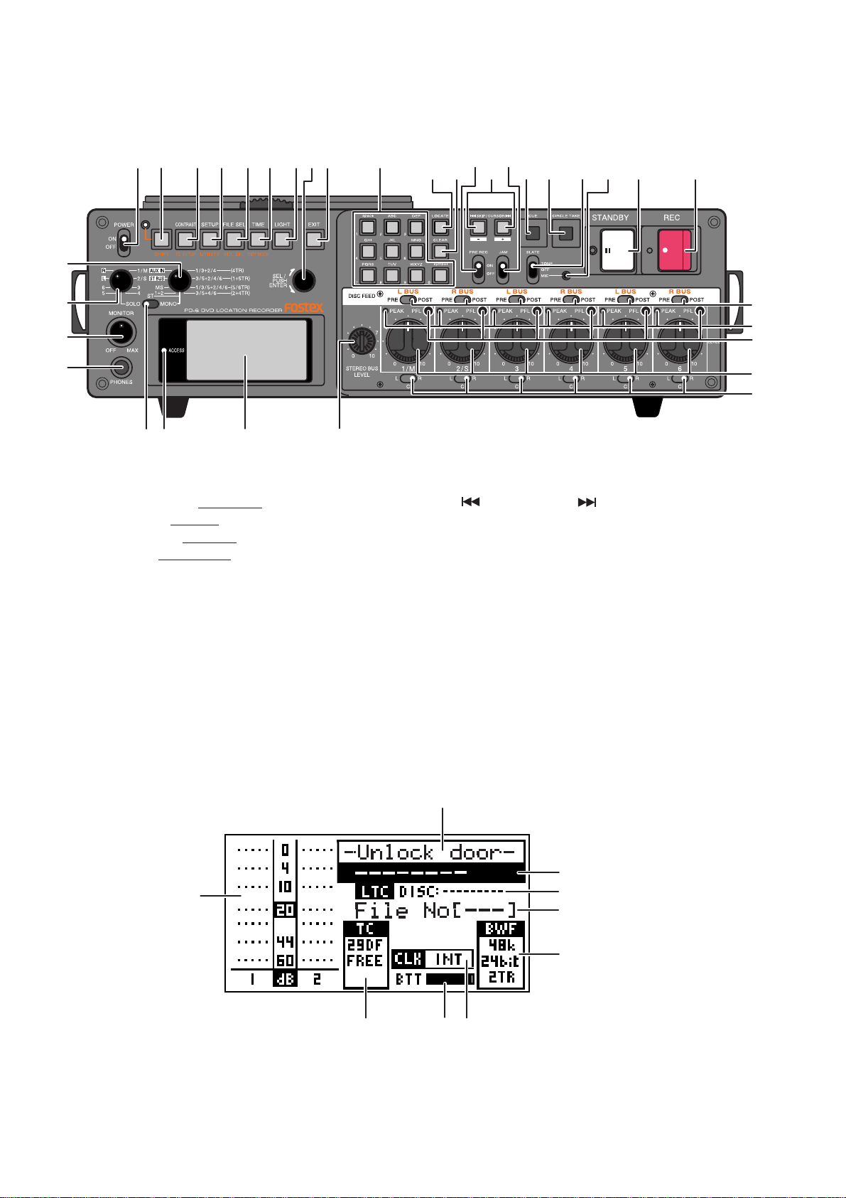
PD-6 Service Manual
2. CONTROLS, INDICATORS & CONNECTORS
1. [POWER] switch
2. [SHIFT] key / LED
3. [CONTRAST / TC SETUP] key
4. [SETUP / UTILITY] key
5. [FILE SEL / EDL SEL] key
6. [TIME / DISP MODE] key
7. [LIGHT] key
8. [EXIT] key
9. [SEL] dial / [ENTER] key
10. LCD display
11. [ACCESS] LED
12. [PHONES] jack
13. [MONITOR] knob
14. [SOLO] monitor select switch
15. Monitor mode select switch
16. [ST/MONO] monitor select switch
17. 10 key
18. [LOCATE] key
19. [CLEAR] keys
20. [SKIP/CURSOR ]key
21. [CUE] key
22. [CIRCLE TAKE] key
23. [STANDBY] key / Indicator (green)
24. [REC] key / Indicator (red)
25. Slate microphone
26. [SLATE] select switch
27. [JAM] switch
28. [PRE REC] ON/OFF switch
29. [DISK FEED] switch
30. [PEAK] indicator
31. [PFL (Pre Fader Listen)] key
32. [LEVEL] knob
33. [PAN] switch
34. [STEREO BUS LEVEL] knob
< FRONT PANEL Section >
17 18 19
34
33
32
31
29
30
282027 21 22 26 23 24
25
16
15
13
12
11 1014
12 34 56798
< LCD DISPLAY Section >
2
3
4
5
6
789
1
1. Level meter section
2. File name field
3. Time display field
4. Remain field
5. File number field
6. File information field
7. Clock field
8. Battery field
9. TC field

9
PD-6 Service Manual
< TOP PANEL Section >
78 6910
11
12
54321
23 22 21 20 19
18
17
16
15
14
13
1. [TC GEN] switch
2. [FRAME] switch
3. [CLOCK] switch
4. [FS/24] select switch
5. [REC TR] select switch
6. [AUDIO FILE] select switch
7. [TC OUT] switch
8. [PULL UP/DOWN] switch
9. [OPEN] lever
10. [EJECT] lever
11. [DISC UNLOCK] button
12. Disc tray section
13. [INPUT MODE] switch
14. [PHASE] switch
15. [INPUT GAIN] knob
16. [HPF] knob
17. [HPF] switch
18. [LIMITER] switch
19. [STOP] key / Indicator (green)
20. [PLAY] key / Indicator (green)
21. [F FWD] key / Indicator (green)
22. [REW] key / Indicator (green)
23. [PANEL LOCK] switch
10
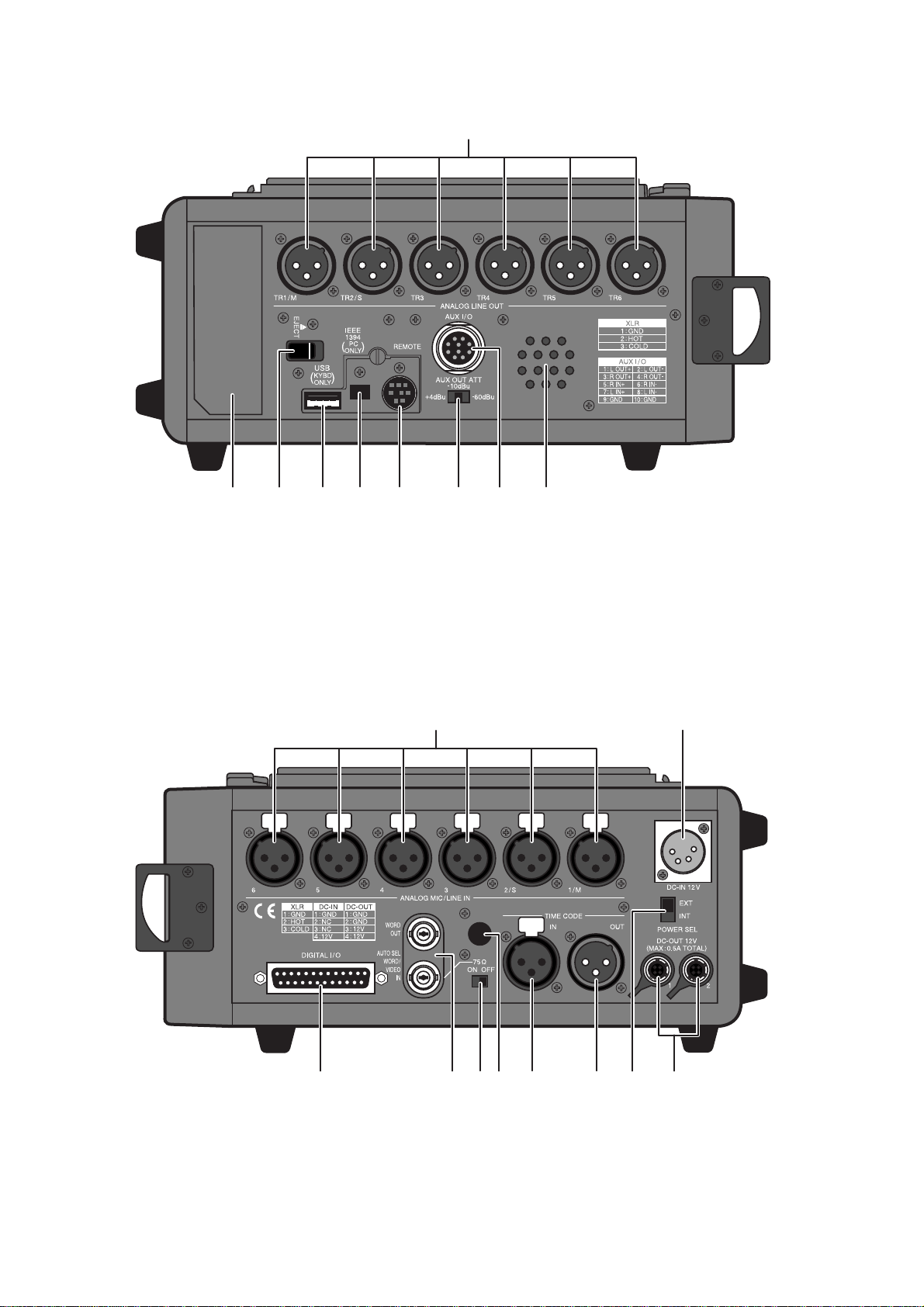
PD-6 Service Manual
1. [ANALOG LINE OUT] connectors
2. Internal monitor speaker
3. [AUX I/O] connector
4. [AUX OUT ATT] switch
5. [REMOTE] connector
6. [IEEE1394] connector
7. [USB] connector
8. [EJECT] lever
9. Battery housing
< SIDE PANEL (left) Section >
< SIDE PANEL (right) Section >
1. [ANALOG MIC/LINE IN] connectors
2. [DC-IN 12V] connector
3. [POWER SEL (INT/EXT)] switch
4. [DC OUT] connector
5. [TIME CODE OUT] connector
6. [TIME CODE IN] connector
7. [WORD IN] terminate switch
8. Blank cap for installing options
9. [WORD/VIDEO IN], [WORD/OUT] connector
10. [DIGITAL I/O] connector–
8 7 6 5 43 29
1
37 69
2
10
1
8 5 4

11
PD-6 Service Manual
3. SOFTWARE UPDATE
The PD-6 software can be updated by placing a software update file in the top directory tree on the 8 cm DVD-RAM
disk formatted by PD-6. There are two ways of copying the software update file from PC to the disk. Read through the
following procedures for proper software update.
3-1. MAIN PCB Software Update Procedures
3-1-1. There is an ATAPI, IEEE1394 or USB DVD-RAM drive exists in your PC environment;
1) Push down 2 pcs. of lock pins located at the lower left side on both
A and B sides of 8 cm DVD-RAM disk by using the tip of a ball
point pen, etc. Then, spin and move the lock pins out and around.
2) Take out the 8 cm DVD-RAM disk out of the cartridge and place
it in the indent of the DVD-RAM drive tray.
3) Extract the WinZip compressed software file “PD6VXXX.zip” and
copy the newly created software update file “pd6mXXX.mot” to
the top directory tree of the DVD-RAM disk. (“XXX” indicates
the software version number. If the software version is V1.02, the
software update file name will be “pd6m102.mot”.)
4) After copying the software, take out the 8cm DVD-RAM disk, put
it back to the cartridge and load it to the PD-6 DVD-RAM drive.
When putting a bare DVD-RAM disk back to the cartridge, be
sure that the side A of the disk conforms with the cartridge’s A
marking.
5) Power on PD-6. In the initialize stage, PD-6 automatically finds
the software update file placed in the top directory tree and is put
into the software update mode. The LCD example on the right
indicates that the PD-6 MAIN software is going to be updated to
V1.02 using the software file “pd6m102.mot”.
6) In the condition that the LCD example on the right is displayed,
press the ENTER key (knob) to update the software.
PD-6 starts updating the MAIN software. The LCD shows “Erase
ROM” (flashing) and then “Write PGM” (flashing).
7) After updating the software is completed, PD-6 is automatically
put initialized, booted up again and is put into the software update
mode. Press the EXIT key. (Depending on the current software
version, there is a case that powering off and then back on PD-6
might be required. Also there is a case that the display contents
differ from those listed in this page.)
8) Confirm the software version by the “Version” SETUP menu ex-
plained later.
DVD-RAM cartridge
DVD-RAM Drive

12
PD-6 Service Manual
3-1-2. There is no ATAPI, IEEE1394 or USB DVD-RAM drive exists in your PC environment;
NOTE:
As mentioned in the PD-6 owner’s manual, depending on the operating system running on your computer, an
IEEE1394 driver software must be installed in your computer to allow to recognize the UDF formatted PD-6
DVD-RAM disk as a rewritable medium prior to the software update.
1) Select the IEEE1394 Utility menu and press the ENTER knob.
Then, turn the ENTER knob to right to select “CONNECT” and
press the ENTER knob again.
By putting PD-6 into the IEEE1394 mode, all functions are
disabled.
2) Connect the IEEE1394 cable between PC (Desktop PC: 6-pin,
Laptop PC: 4 or 6-pin) and PD-6 (4-pin) IEEE1394 ports.
3) Wait for a while until PC recognizes PD-6 with 8 cm DVD-RAM
disk loaded as an external rewritable removable drive / disk.
4) Extract the WinZip compressed software file “PD6VXXX.zip”
and copy the newly created software update file “pd6mXXX.mot”
to the top directory tree of the DVD-RAM disk. (“XXX” indicates
the software version number.)
5) After copying the software, select PD-6 (FOSTEX FX-FIRE IEEE
1394 SBP2 Device - (*)) and remove it from PC. (*: Drive No. on
your PC)
6) Disconnect the IEEE1394 cable from the PC / PD-6 and turn off
the IEEE1394 mode.
In the initializing stage, PD-6 automatically finds the software
update file placed in the first directory tree and is put into the
software update mode.
7) Press the ENTER key (knob) to update the software.
PD-6 starts updating the MAIN software. The LCD shows “Erase
ROM” (flashing) and then “Write PGM” (flashing).
8) After the software update is completed, power off PD-6 and then
back on. (Depending on the software version, there is a case that
PD-6 is automatically initialized and is booted up.)
9) Confirm the software version by the “Version” SETUP menu.

13
PD-6 Service Manual
3-2. DVD-RAM Drive Firmware Update Procedures
There are two firmwares for DVD-RAM drive, which can be updated by a similar method explained before. Although
the DVD-RAM drive firmware update will not occur as many times as the MAIN PCB software update, read through
the following explanation for correct update procedures.
1) Copy the DVD-RAM drive firmware update file
“mkXXXrev.bin” to the top directory of the DVD-RAM
disk either by direct software file copy onto a 8 cm DVD-
RAM bare disk or by putting PD-6 into the IEEE1394
mode and connecting to PC.
2) In the initialize stage, PD-6 automatically finds the
firmware update file in the top directory tree and is put
into the update mode. The example on the right indicates
that there is a firmware update file “mk0b1rev.bin” exists
in the top directory tree.
3) Press the ENTER knob to update the DVD-RAM drive
firmware.
The firmware update remaining time starts counting down.
It will take about 100 seconds (1 minute and 40 seconds)
to complete the firmware update.
4) After the software update is completed, the message “Pls
Power Off!” will appear on the PD-6 LCD. Power off
PD-6 and then back on. (Depending on the software ver-
sion, there is a case that PD-6 is automatically initialized
and is booted up again.)
5) Select “Reset setup memory” in the SERVICE menu ex-
plained later in this manual, press the ENTER knob and
press the ENTER knob again while “SURE?” is flashing
on the LCD to reset the memory.
6) Confirm the software version by the “Version” SETUP
menu.

14
PD-6 Service Manual
4. SERVICE MENUS
Various Service menus in addition to the normal SETUP menus are
available on PD-6 in order to judge if the unit is working correctly.
4-1. Accessing to Service Menus
1) Power on PD-6.
2) While holding down the STOP key, press the SETUP key.
The Service menus are displayed in addition to the normal menus.
4-3. Reset setup memory
This menu is used for resetting various parameters in the SETUP
menus to the default value such as “Ref.level” to “-20dB” and “Peak
hold” to “3sec”. Also executing the MEMORY RESET is nececsary
after updating the MAIN software.
To reset the setup memory, select the “Reset setup memory” Service
menu and press the ENTER knob. Then, while “SURE?” is flashing,
press the ENTER knob again. After the “Completed!” message
appears for a short while, the LCD returns to the SETUP / SERVICE
menu select display.
CAUTION:
Every time the MAIN software is updated, execute the “Reset setup
memory”.
SETUP
MENU
SERVICE
MENU
4-2. Software & Firmware Version
Although this is not a Service menu, the PD-6 MAIN software
version as well as the DVD-RAM drive firmware version can be
confirmed. To check, select the “Version” menu and press the
ENTER knob.
There are three versions displayed in the “Version” menu.
The top one (“Ver1.02 14/MAY/’03” on the right example) is the
PD-6 MAIN software version number. The middle one
(“K0B1.04.05.REV” on the right example) and the bottom one
(“K00B.02.15REV on the right example) indicate the DVD-RAM
drive firmware version number.
If the new MAIN software and / or the DVD-RAM drive firmware
are sent from us, check the version number in this menu after updating
the software / firmware.
MAIN software version
and programming date
DVD-RAM drive firmware version
and programming date

15
PD-6 Service Manual
4-4. Self Check
The Self Check Service menu checks if the following circuits works
properly in order.
•AES/EBU IN and OUT circuit
•LTC IN and OUT circuit
• AATON ASCII circuit
•WORD IN and OUT circuit
•USB circuit
Preparation:
Before executing the Self Check menu, the following PD-6 connectors must be connected.
•AES/EBU CH 1-2/3-4/5-6 INPUT and CH 1-2/3-4/5-6 OUTPUT using a D-SUB 25-pin <-> XLR male x 4 / XLR
female x 4 cable such as HOSA DBK-258
•LTC IN and OUT using a XLR male <-> female cable
•WORD IN and OUT using a BNC <-> BNC cable
•USB keyboard
To execute, press the ENTER knob in the condition that “Self Check” is highlighted. PD-6 automatically checks
the above mentioned circuits. In order to skip one or some of the above checking items, press the EXIT key.
•Display example when PD-6 circuit works properly:
• Display example when PD-6 circuit does not work properly:

16
PD-6 Service Manual
4-5. Front Check
This menu checks if the toggle / rotary / tact switches and LEDs on the PD-6 front panel are correctly working. To
check the switches and LEDs operation on the front panel, select the “Front Check” Service menu and press the
ENTER knob. To get out of this menu, press the ENTER knob again.
• Tact switches (25 pcs. in total)
The switch number 1 through 25 and the corresponding name (i.e.:
[1] SHIFT) are displayed on the LCD every time the tact switch is
pressed.
• Rotary switches (2 pcs. in total)
The number 1 through 8 is displayed on the LCD depending on the
SOLO and MONITOR rotary switch position.
•Toggle switches (4 pcs.)
STRO (stereo) / MONO / SOLO, ON / OFF and T / none (blank) are displayed on the LCD depending on the
SOLO monitor select / PRE REC / JAM / SLATE select toggle SW position respectively.
•LEDs
The REC LED flashes in RED and the STANDBY, SHIFT and ACCESS LEDs flash in GREEN.
Flash in green
Flash in green Flash in green
Flash in red

17
PD-6 Service Manual
4-6. Mixer Check
This menu checks if the toggle / rotary / tact switches and LEDs on
the PD-6 top panel are correctly working. To check the switches
and LEDs operation on the top panel, select the “Front Check”
Service menu and press the ENTER knob. To get out of this menu,
press the ENTER knob again.
• Tact switches (5 pcs. in total)
The switch number 1 through 5 and the corresponding name (i.e.:
[1] OPEN) are displayed on the LCD every time the tact switch is pressed.
• Rotary switches (5 pcs. in total)
The number is displayed on the LCD depending on the REC TR, FS/24, CLOCK, FRAME and TC GEN rotary
switch position.
•Toggle switch (10 pcs.)
BWF / OPT, REPRO / GEN, -0.1 / 0.0 / +0.1 and ON / OFF are displayed on the LCD depending on the AUDIO
FILE, TC OUT, PULL UP/DOWN, CH1 ~ 6 LIMITER ON/OFF and PANEL LOCK toggle SW position
respectively.
•LEDs
The REWIND, F FWD, PLAY and STOP LEDs flash in GREEN.
Flash in green
Flash in green
Flash in green
Flash in green
Flash in green
Flash in green
Flash in green
Flash in green

18
PD-6 Service Manual
4-7. Flash ROM
There is a Flash ROM Card PCB prepared for the PD-6 MAIN
PCB. The Flash ROM Card PCB (P/N: 8274354000) is used if
something wrong happens during software update (i.e. power
shutdown, blackout). The Flash ROM Card PCB allows to boot up
PD-6, copy the system software in the Flash ROM Card PCB to the
Flash ROM on the PD-6 MAIN PCB using this “Flash ROM”
Service menu. Furthermore, you can rewrite the programming inside
the Flash ROM on the Flash ROM PCB.
• Rewriting the Flash ROM Program on Flash ROM Card PCB
NOTE:
In order to rewrite the Flash ROM program on the Flash ROM Card
PCB, PD-6 which works in good order must be prepared.
1) Power off PD-6 and disconnect the power cable from the AC adapter
AD-15C or remove the NP-1 type internal battery.
2) Open up the bottom cover.
3) Set the SW S1 on the Flash ROM PCB to “INT” side and plug it
into the 50-pin connector J3 on the MAIN PCB.
U721
R858
R859
C755
R856
+
C757
R755 R756
R759
R766
U716
W701
C819C820
C821
C822
1
5
U723
W706
W707
W708
R863
C703 C705
+
C722
+
C723
+
C724
+
C741
+
C742
+
C743
C744
C745
C746
C750
C760
+
C761
J702
2
1
R765
R771
R772
R773
R784
R785
R786
1
8
U702
1
8
U703
1
9
U711
1
9
U712
W702
W703
W704
W705
C701
C706
+
C719
+
C720
+
C721
+
C738
+
C739
+
C740
C747C749
+
C751
C762
C772
+
C773
+
C774
+
C777
+
C794
C795
C798 C800
+
C803
+
C809
L801
L809
Q705
R781
R782
R783
R815
R816
R817
R818R821
R822
R824
R825
R828
R830
R831 R832
R833
R834
1
8
U701
1
8
U704
1
5
U706
1
9
U710
1
9
U713
U714
C79
R66
R67
R862
L702
C702 C704
C733
C734
+
C736
+
C737
+
C766
C771
1
8
U14
1
8
U707 U717U718U719U720
+
C824
52 13
64
78
+
C825
+
C826
4
1
J1154
L701
C763
+
C770
C779 C780
C781 C782
C786C787
C789
C796C797
C799
C806
C937
C938
C939
C940
C941
C942
C1157
+
C1172
J1152
L910
L916 Q706
R800 R801
R803
R804
R806
R807R811
R819
R820
R826
R827R829
R835
R836
R837
R838
R839
R840
R842R843
R932
R1189
R1190
51
610
C804
C805
C807C808
C1161
+
C1165
+
C1166
D703
R823
R841
1
8
U705
80100
36
20
1
40
72
U1152
108
R931
R933
R934
U908
1
2
3
4
C930
+
C932
C1154
C1155
C1160
C1164
C1181
C1182
D903 D904
D905
43
21
R928
R1177
R1181
R1182 R1183
R1184
R1185 R1187
15
U904
U907
C1156
C1162
E1151 E1152
R1152
R1153
R1154
R1156
R1157
R1158
R1188
W1151
X1004
W1153
R1192
2
34
1
X5
C3
+
C5
C10
C12
C17
C23
C26
C27
C33
C35
C62
C64
C66
C71
+
C85
+
C90
R65
U41
R68
R69
C83
C84
C92
C94
C97
R64
R70
C1151
C1152
C1163
19
J902
R3
R4
R5
R9
R10
R11
R19
R20
R47
R48
R49
R50
R51
R58
R59
R1155
R1175
R1176
160
61
240
120
181
U6
1
8
U12 1
13
U13
1
13
U18
1
8
U1154
W1
W2
W1152
X2
J5
1
2
C7
C9
C18
C87
C89
D4
D5 D6
D7 D8
1
9
U1151
C15
C29
C42
C44
C52
1
23
4
X1
R6
R7 R12
R13
R17
R18
1
11
U19
B1
C78C11
C14
+
C19
C20
+
C21
+
C22
C24
C25
C28
+
C31
C36
C38
C40
C49
C50
C51
C53
C74
C75
C76
C82
C96
U37U38
1
11
U24
1
11
U27
1
11
U35
E5
D1 D2
E3
E4
14
17
8
/RESET
TDO
TMS
TDI
/ASEBRK
/TRST
TCK
J2
R2
R8
R21
R22
R23
R25 R33
R37
R39
U21
U25
U28
1
U29
X3
+
C13
15
U5
C34
C43
C48
C54
C57
1
8
U40
J1
12
R34
U7
1
28
U10
1
8
U16
C1
C2
1
24
3
C181
C182
C183
C184
C185 C187
C188
C191
C195
C196
C197
D10
C285 C287
C288
C291
+
C381
C382 C384
C385 C387
C388
C391
C395
C397
+
C1002
C1007
C1008
C1011
D3
E1
E281
E381
E1001
L1003
L1004
R1
R14
R16
R41
R181
R182 R183
R184
R185
R186
R187
R189R190
R191
R281
R282 R283
R284
R285
R286
R381
R382 R383
R384
R385
R386
R387
R389R390
R391
R1002
R1004
R1005
R1007 R1008
R1075
U2
1
U3
1
9
U9
U26
1
10 20 30
50
60 80
100
U181
1
10 20 30
50
60 80
U381
10 20
50
60
100
80
30
U1002
1
1
9
U1004
1
8
U1005
C396
+
C1005
C1019
C1041 C1044
C1046
+
C1049
C1053
L181
L281
L381
L1001
R188 R288 R388
R1001R1003
R1019 R1020
R1022 R1023
1
8
U1
6
21
3
X1001
C59
C60
+
C63
C65 C67
C68
+
C73
W901
W902
+
C186
C929
+
C931
C1004
C1006
C1009
C1016
C1017
C1018
C1021
C1022
C1030
C1048
+
C1054
C1060
C1123
E1002
E1005
E1006
L1005
L1006
L1007
R1006
R1010
R1012
R1024
R1027
R1034
R1037
1
11
U20
1
9
U30
20
40 50
90
80
100
30
70
U1008
1
U1009
U1010
U1011
1
U1019
1
U1032
1
X1002
C93
C1024
C1025
C1026
C1029
C1032
+
C1034
C1035
C1042
C1045
C1051
C1052
C1064 C1066
C1068
C1075
C1082
C1086
+
C1095
+
C1109
D1001
D1002
D1003
E1003 E1004
L1011
L1012
L1013
R1009
R1011
R1028
R1031R1032
R1033 R1035
R1036
R1046
R1059
R1060
1
13
U15
U1012
U1015
U1016
U1017
1
8
U1020
1
33
20
19
32
51
52
64
U1024
C1124
1U1034
C1079
+
C1088
C1089
C1091
C1094
C1098
C1099
C1102
C1103
C1107
C1108
C1110
C1112
+
C1113
+
C1114
+
C1115
+
C1116
C1117 C1118
D1004
D1005
D1007
D1008
D1009D1010D1011
1
S4
G
2H
3C
L1014
L1015
L1016 L1017
R1038
R1039
R1040
R1043
R1047
R1054
R1055
R1061
R1063
R1064
R1067
R1068
R1069 R1071
R1072
R1073
R1074
13
1
U1007
1
8
U1026
1
8
U1028
1
5
U1029
1
U1030
5
1
U1031
+
C1090
G
C
H
1
5
6
4
3
2
R1052
R1062
R1076
R1077
R1078
+
C948
+
C947
+
C950
+
C951
+
C952
1
Q903
1
Q904
R943 R944
C189
+
C286
R946
R948
+
C386
C389
+
C903
C904
C905
C908
C909
C911
C914
C915
C917
C918
C923
C924
C925
C926
+
C935
+
C936
+
C949
+
C1028
11
J901
1
C1055
C1056
+
C1071
C1119
C1120
D906 D909D910D912 D915D916
D1006
L1008
L1018
L1019
1
Q901
1
Q902
R903
R904
R905
R910
R911
R912
R913
R918
R921
R1048
R1065
R1066
R1070
1U182 1U282 1U382
1
9
U902
15
U903
D918 D919
W903
W904
C289
R947
R922
R924
C1159
C41
49
502
1
J3
C37
C39
C47
POWER
EXT ROM
POWER
RED
PCB,MAIN,PD-6
JTAG
~
EXT DRIVE
USB
(FIRE-USB1 LOAD)
D-
DGND
D+
~
Connector J3 Location on MAIN PCB
Front Side
8252510001
(FLASH)
EXT
INT
PCB,FLASH-ROM CARD
+
C1
C2
50
49
2
1J1
R1 S1
25
1
U1
TOSHIBA K29284
TC58FVT160FT-10
MAIN PCB
Flash ROM card PCB

19
PD-6 Service Manual
4) Connect the AC cable from the AC adapter AD-15C or insert the
NP-1 type battery.
In this condition, PD-6 is booted up using the software program
inside the Flash ROM on the PD-6 MAIN PCB.
5) Select the “Flash ROM” Service menu and press the “ENTER” knob.
6) While “SURE?” flashes, press the ENTER knob.
“Erase ROM”, “Write PGM” and then “Completed!” will appear
on the PD-6 LCD in order.
7) Press the EXIT key or ENTER knob to go back to the SETUP /
SERVICE menu select display.
With the above procedures, the program inside the Flash ROM on
the PD-6 MAIN PCB is transferred to the Flash ROM on the Flash
ROM Card PCB.
• Rewriting Flash ROM Program on the MAIN PCB
1) Power off PD-6 and disconnect the power cable from the AC adapter
AD-15C or remove the NP-1 type internal battery.
2) Open up the bottom cover.
3) Set the SW S1 on the Flash ROM PCB to “EXT (FLASH)” side
and plug it into the 50-pin connector J3 on the MAIN PCB.
4) Connect the AC cable from the AC adapter AD-15C or insert the
NP-1 type battery.
In this condition, PD-6 is booted up using the software program
inside the Flash ROM on the Flash ROM PCB.
5) Select the “Flash ROM” Service menu and press the “ENTER” knob.
6) While “SURE?” flashes, press the ENTER knob.
“Erase ROM”, “Write PGM” and then “Completed!” will appear
on the PD-6 LCD in order.
7) Press the EXIT key or ENTER knob to go back to the SETUP / SERVICE menu select display.
With the above procedures, the program inside the Flash ROM on the Flash ROM Card PCB is transferred to the
Flash ROM on the PD-6 MAIN PCB.
4-8. EE Mode
By turning on the EE mode, the A-to-D and D-to-A converters
circuitry on PD-6 are directly connected. This menu is used for
measuring the frequency response, S/N and Dynamic Range value
for Quality Control purpose.
•Turning on the EE mode
1) Press the ENTER knob while the EE mode menu is selected.
The default setting “Off” flashes.
2) Rotate the ENTER knob to change the setting to “On” and press the
ENTER knob again.
NOTE:
The EE mode on / off condition will not be battery backed up. Even
if the PD-6 power is turned off with “EE MODE: On” condition,
powering on PD-6 again will initialize the EE mode setting to the
default value (Off condition).

20
PD-6 Service Manual
5. ERROR CODE / ALERT LIST
The Table below indicates the error code number and corresponding description. Since the error code list is basically
designed for our engineers to improve the software, the description is quite technical. If you find PD-6 displaying the
error codes, we encourage you to update the software to the latest one first. In case updating the software does not solve
the problem, we would like you to contact us.
4-9. BATT volt (Battery Voltage)
This menu monitors either the AC adapter DC voltage (POWER
SEL SW setting: EXT, EXT_PWR_DETECT fed to pin-238 (AN6/
PTL6/DA1) of CPU U6 (SH7727)) or the NP-1 type battery DC
voltage (POWER SEL SW setting: INT, INT_BATT_DETECT fed
to pin-239 (AN7/PTL7/DA0) of CPU U6). If the DC voltage is
around 15V, the 4-digit hexadecimal value will be around 0240.
4-10. MemoryDump
This menu is only utilized at our manufacturer and has nothing to
do with servicing PD-6.
Error / Alert
ERROR=0
ERROR=1
ERROR=20
ERROR=21
ERROR=83
TimeOut Read!
Read Error!
Disc Error! Write
Write Error
Event Over!
Diagnoses write!
Rec Timeout Err!
Rec Caution!
File Size Over!
Write Error!
Description, cause and treatment
Not defined.
Trying to access the sector address other than the accessible region on disc.
The file size exceeded the specified capacity (2GB or 4GB) while in REC mode. This error code will be
deleted on V1.03 software onwards.
Shortage of capacity while in REC mode occurred. This error code will be deleted on V1.03 software on-
wards.
Failed to Block-Erase while in the Flash ROM SAVE (writing) mode.
Time-out occurred when reading out data. Drive malfunction, disc failure, dust & dirt on the DVD-RAM
disc.
An error occurred when reading out data. Disc failure, dust & dirt on the DVD-RAM disc.
Time-out occurred when writing in data. After this error message appears, PD-6 initializes the DVD-RAM
drive. Disc failure, dust & dirt on the disc. Changing to a new disc or physical-format a disc is highly
recommended.
An error occurred when writing in data. Disc failure, dust & dirt on the DVD-RAM disc. Changing to a new
disc or physical-format a disc is highly recommended.
Too much disc fragmentation (discontinuous sector region) exceeding the UDF management while record-
ing an audio files. The disc on which editings were executed on PC were used on PD-6. This error rarely
occurs. The cause could be other than PD-6.
An error list information "file name.dia" was created because an error occurred when writing in audio data
on the disc.
A cache buffer overflowed and audio files could not be completed recorded on the disc. Dust & dirt on the
disc, failure sectors forcing the frequent retry of writing in data and / or many alternative sectors are used.
There is a possibility that a cache buffer overflowed and audio files could not be completed recorded on the
disc. Dust & dirt on the disc, failure sectors forcing the frequent retry of writing in data and / or many
alternative sectors are used.
The file size exceeded the specified capacity (2GB or 4GB) while in REC mode. Rarely occurs. It is consid-
ered that some sort of system error occurred.
A Verify Error occurred when recording audio files. Dust & dirt of disk, failure sectors. Since alternative
sectors are used, this error rarely occurs.
Other manuals for PD-6
4
Table of contents
Other Fostex DVD Recorder manuals


