Fostex R8 User manual
Owner’s
Manual
Model
8
TRACK
RECORDER/REPRODUCER
RISK
OF
ELECTRC
SHOCK
DO
NOT
OPEN.
CAUTION:
TO
REDUCE
THE
RISK
OF
ELECTRIC
SHOCK,
DO
NOT
REMOVE
COYERIOR
BACO.
NO
USER
SENVICEABLE
FAHTS
INSIDE.
REFER
SERVICING
TO
QUALIFIED
SERVICE
PERSONNEL.
The
зоната
fish
wit
arounead
sym
hin
an
equilateral
trangle,
mendes
f
Mange
intended
о
der!
the
wer
lo
the
leni
he
usc
lo
the
presence
ol
uninsuted
resenco
cl
препат
operating
and
nante
апостола
volage
win
the
product
en
ance
pervcn]
aruciore
eine
erar
Closure
a
may
bool
зинен
rage
to
accompanyna
1o
apzhence.
onsite
а
nek
of
electric
shock
to
persone,
"WARNING
то
REDUCE
THE
пик
OF
NRE
OR
ELECTRIC
SHOCK,
DO
NOT
EXPOSE
THIS
APPLIANCE
TO
RAIN
OR
MOIS:
TURE
SAFETY
INSTRUCTIONS
1,
Bead
lnstuctens
—
Al
the
safety
and
cperairg
instruc-
"loro
should
be
read
boire
the
орање
5
operated.
2.
Roran
notuchonc.
The
calc
andopomirgirsi
cine
Heal
—
The
apotance
shouid
te
stuaed
away
fom
heet
appliances
inching
ampiikers)
hat
produce
heat.
shuld
be
топоз
for
lie
relerence,
10.
Power
Sources
—
Tre
apolance
should
beconneciedioa
3.
Heed
Warnings
~All
warnings
on
he
apolanceand
n
no
power
supply
опу
cl
he
ype
described
inthe
operating
орао
bs
Gd
d
P
патас
or
as
ame
on
ne
apprarce.
4.
Folwisrucions
—
Aopeamng
ancusewsusens
175
Grownding
or
Pelareaton
—
The
precautions
hat
shouid
Should
bo
followed,
Бо
takenso
athe
grunding
огра
means
ot
Е
зп
appllonce
is
not
deleted
5
Waer
апа
Moisture
—
The
appliance
should
nol
be
used
пен
water
—
bx
example,
near
а
bathtub,
мавлон,
i
72.
Power
Cord
Proecton
—
Power
supply
cords
should
ba
heh
sni,
uncut
n
a
wet
basemert,
or
neat
ави
‘uted
39
Wei
hey
are
nol
kely
lo
be
walked
on
cr
"ring
pecore
de
I
pinched
by
teme
paced
upon
or
against
тет
paying
ко
onl
Sande
The
asians
abana
Ba
usq
ery
рала,
altanton
to
corde
at
lugs,
comenience
recer
wih
a
cat
or
stand
hal
s
recommended
by
he
тали
Гасот,
and
the
por
where
еу
exi
Fort
Ine
applence,
Тате
13.
Geanng
—
The
apphance
should
be
cleared
only
as
recommended
by
Po
таласи
14,
Nomco
Войово
Tho
powar
cord
oltre
appliance
shouid
Бе
unplugged
from
the
cult
uhan
lat
unused
or
a
long
риот
ot
ire.
18.
Objed
and
qud
елуу
—
Care
should
be
taken
so
nat
objects
со
not
alana
дае
are
not
spled
mo
ne
onc
ои
through
оросо.
16.
Damage
Requieng
Samice
—
The
appliance
shouid
be.
An
appliance
and
cari
combination
atoud
be
moved
чип
oare:
Quick
steps,
excessive
force,
апа
uneven
Sufaces
maycause
пе
appiance
and
cari
combnaton
to
overturn
T,
Wat
or
Gang
owning
те
aco
face
8.
Venkicion
—
The
appiance
should
be
stuted
so
that
is
locaton
or
postion
does
not
пес
wih
ts
proper
vent
lion.
or
example,
the
appliance
should
no
be
stus
(ON
a
bad.
sota
rug,
or
sim
surtaca
tal
may
bici
he
wortlaton
openings;
о,
placed
in
a
bui-n
talon
Such
asa
bookcase
о
canet
rat
тау
impede
helow
ol
fr
fvcugh
he
ventiation
pennos
serviced
by
qualia
sarvoe
personnel
when
А
The
power
supply
ood
cr
ne
plug
has
been
demagec:
8
Objecs
have
tate,
or
tule
has
been
sped
no
the
police:
or
C
The
agphance
has
been
exposed
10
iain:
or
D.
The
acplance
does
not
appsarlo
operate
normally
o
vbt
а
marked
craroe
n
perlormance,
ar
E.
Tho
appliance
тыз
ten
copped.
or
he
enclosure
Еј
appliance
beyond
that
cescribed
in
he
operating
лани:
dens.
Al
oier
servo
shouid
be
relered
to
aualiod
Service
personne
тво
Sep.

INTRODUCTION
‘Congratulations
on
your
purchase
of
the
Fostex
АЕ
Even
lighter
and
more
compact
than
its
predecessors,
the
R8
has
many
advanced
features
that
make
high-quality
muti-reck
recording
easier
тап
ever
The
control
pene!
is
detachable
and,
when
combined
with
the
optional
extension
cable
Model
8544,
it
functions
аз
а
practical
remote
control
unit
with
builtin
peak
level
meter
‘The
microprocessor
controled
R8
has
a
host
of
new
fea-
tures
made
possible
by
a
sophisticated
new
4.54
serial
CPU:
auto
ocate
of
up
to
10
different
memory
points,
адо
return,
shuttle
play,
zone
limit
and
other
helpful
features.
The
numeric
key
pad—a
fist
among
multi-track
recorders
—
makes
programming
very
easy
and
tne
мо
6-cigh
LED
Gisplays
aways
tel
you
what's
going
on.
“The
transpot
assembly
аво
offers
substantiel
improve:
ments
such
as
a
com
drive,
superior
mechanical
precision
nti
now
available
only
on
the
most
expensive
open
reel
recorders.
We
wish
you
many
years
of
creative
enjoyment
with
your
rew
FOSTEX
РА
ABOUT
THIS
MANUAL
тна
manual
has
been
writen
with
both
newcomers
to
multitrack
recording
as
well
as
experienced
users
in
mind.
If
you
already
have
experience
with
MTRs,
you
сап
skip
those
secions
containing
information
you
are
already
famlier
with,
such
as
SETUP
or
ROUTINE
MAINTENANCE.
Consde,
though,
thet
the
RB
Б
а
very
sophisicded
machine
with
a
host
of
new,
computer-coniroled
features.
‘Tobe
able
'o
make
пе
most
of
пе НА
we
recommend
па:
you
read
the
erüre
marual
while
actually
operating
the
recordes
Tre
first
section,
SETUP,
explains
how
to
install
your
new
R8,
what
сос
and
tapes
lo
use
and
how
to
load
tape
k
also
gives
you
important
information
on
sound
signal
and
syne
connections.
Once
you
have
thus
set
up
the
RB,
read
section
І,
the
FEATURE
AND
FUNCTION
OVERVIEW.
This
secion
‘shows
you
how
to
detach
the
remote
control
panel
from
the
‘main
urit
and
then
explains
the
basie
tape
transport
tunc-
tions
The
advanced
microprocessor-controled
features
ct
the
RB
aro
ао
shortly
introduced
here.
Section
Il,
RECORDING
AND
PLAYBACK,
tells
you
all
абай
the
recording
process,
explaining
the
major
multi-
tack
techniques
such
as
overdubbing,
punch
infout
and
ping-pong
recording.
The
EDITING
saction
then
goes
оп
to
show
you
how
to
use
a
razor
blade
and
spicing
block
to
create
your
final
track
tape.
ADVANCED
FEATURES
gives
you
all
the
information
necessary
to
operae
the
sopnisiceted
computer-con-
tolled
functions
of
the
F8,
such
as
locate.
ашо
return
and
zone
limit
The
LIST
OF
FEATURES
io
mainly
intended
as
а
quick
rolororca
guide
to
all
R8
features
and
‘unctions
but
it
also.
contains
adcitionel
detaile
such
as
the
working
of
some
LEDs.
You
might
wart
to
skim
through
this
section
first
to
ае!
to
know
the
RB
and
is
many
possibiites.
To
under-
stand
most
operations,
however,
you
wil
have
to
read
the
various
precedng
sections.
Finaly,
ROUTINE
MAINTENANCE
shows
you
how
to
keep
your
H8
in
top
operating
cordon.
CONTENTS
SECTION
1.
SETUP
-
Placement
A)
CONNECTIONS.
Cables
Signal
Levels
and
Impedance
Mixer
Comections
Syne
Connection
Foot
Switch
Comections
AC
Connection
B)
LOADING
TAPE
Recommended
Tapes
Loading
Tape
Switching
On
the
А8
SECTION
2,
FEATURE
AND
FUNCTION
OVERVIEW
€
The
Detachable
Control
Pane!
Detaching
the
Control
Panel
Connecting
the
Extension
Cable
Basic
Tape
Tianspor
Functions
FewindiFast
Forward
ley
Stop
Medes
Advanced
Computer-Controled
Functions.
SECTION
3.
RECORDING
AND
PLAYBACK
‘
The
Recording
Proce
Tope
Identification
end
Reference
To
Recording
the
Syne
Track
Recording
Basie
Tacks
‘Additional
SAFEJRDY
functions
Playback
Overdubbing
Practicing
Overdube
vertu
дела! Punch
in/out
Ping-Pong
Recording
сина
Mixdown
Using
a
Synchrenizor
Creative
use
of
the
Pitch
Control
SECTION
4.
EDITING
-+-+
=
eem
ÀÀ (а
SECTION
5.
ADVANCED
FEATURES
.....
в
Preroll
Preroll
Setting
‘Checking
the
Preroll
Time
Tho
Locate
Function
Setting
Memory
Points
Checking
Матогу
Points
Clearing
Memory
Points
Using
LOCATE
AUTO
PLAY
‘The
Aulo
Return
Function
Setting
the
Auto
Return
Points
Using
AUTO
RTN
Checking
the
Auto
Relum
Points
"The
Zone
Limit
Function
‘Setting
the
Zone
Limit
Points
Using
ZONE
LIMIT
(Checking
the
Zone
Limit
Points
Displaying
the
Zone
Limit
Time
‘The
Tape
Ree!
Zone
Function
Calculating
the
Tape
Reel
Zone
Displaying
the
Remaining
Tape
Tine
Memory
Sort
Memory
Sort
Data
and
Functions
Data
Value
Entry
Error
Massages
SECTION
6.
LIST
OF
FEATURES
—
50
SECTION
7.
ROUTINE
MAINTENANCE
-
а
SECTION
8.
SPECIFICATIONS
------------------22
a
section
1.
SETUP
Placement
The
RB
can
be
used
in
either
the
upright
ог
horizontal
posi-
ion.
Since
the
control
pane
is
detachable,
you
will
be
able
to
easily
operate
the
controls
and
waich
the
peak
level
meter
regardless
of
how
you
install
the
ВА.
Place
the
unt
in
a
dry,
well
ventilated,
stable
locaton
away
‘rom
diec!
sunlignt
or
опе!
sources
of
heat.
If
you
use
the
plcna!
contol
pene
extension
cable
(Model
8544)
you
can
operate
the
Пе
up
to
5
meters
away.
Oniy
one
extension
cable
may
be
used.
А)
CONNECTIONS
Cables
Те
obtain
оритит
sound
quailty,
й
8
important
to
use
only
high
quality
audio
cables
with
tightly
braided
shields,
mult
stand
certer
conductors
and
low
internal
capacitance,
such
as
Fostex
Models
8044
1o
8049,
Use
cables
of
the
shortest
piacical
length
and
never
use
cables
more
than
3
meters
(10
leet,
long,
to
avoid
sgnal
deteroration
(high
frequency
losses)
and
Pum.
Keep
the
input
end
output cables
apart
by
a
few
inches
and
as
fer
as
possible
ewey
from
AC
power
cords.
И
усы
cannot
void
intersections
between
power
and
signal
cabies,
try
to
have
tham
cross
at
right
angles.
The
inputs
ard
outputs
of
the
А8
have
АСА-уре
pin
jacks—
use
cables
with
the
corresponding
plugs:
Signal
Levels
and
Impedance
When
hocking
up
the
RB,
t
is
necessary
to
have
a
look
а!
the
output
levels
(measured
in
JBV
or
СВМ)
and
impedance
values
[measured
in
Ohms)
of
the
equipment
you
want
to
connec
to
make
sure
that
they
match
the
specifications
of
the
НА
Level
or
impedance
mismatches
can
lead
to
sound
signal
distorton
and
even
equipment
damage.
‘The
eight
RE
INPUTS
@
are
unbalanced,
high
impedance
jacks
which
accep:
nominal
-
10
dBV
(03
V)
line
level
sig
nale
from
low
ог
high
impedance
sources.
Many
electronic.
musca
instruments
such
as
synthesizers
or
drum
machines
сап
be
conreclod
direclly
to
these
inputs;
however,
micro-
phones,
guitars
and
other
aw
level
saral
sources
cannot
be
patched
to
the
R8
unless
you
use
а
microphone
preamplifier
or
прег
NOTE:
Never
connect
outputs
indicated
in
watts
(W)
such
аз
those
of
a
power
гтрійегіо
the
R8
INPUT
jacks
unes
a
suitable
direct
box
is
used
to
attenuate
the
signal
level
to
around
~
10
ОВИ
Otherwise,
you
may
severely
damage
your
new
tape
recorder.
Mixer
Connections
Though
a
variety
o
signal
sources
can
be
hooked
up
to
пе
RB
INPUTS
rectly,
they
are
generally
used
for
connection
cf
а
murg
consoes
outputs.
‘The
Jacks
of
Input
channels
5
to
8
are
connected
in
parallel
to
the
jects
for
channels
1
thru
4
respectively.
Thus
а
mixer
with
four
buss
outputs
can
feed
all
eight
tracks
c!
your
А8
without
repalching.
NOTE:
Signals
connected
io
INPUT
jacks
5
thru
8
ate
NOT
internaly
routed
io
channels
1
thu
4.
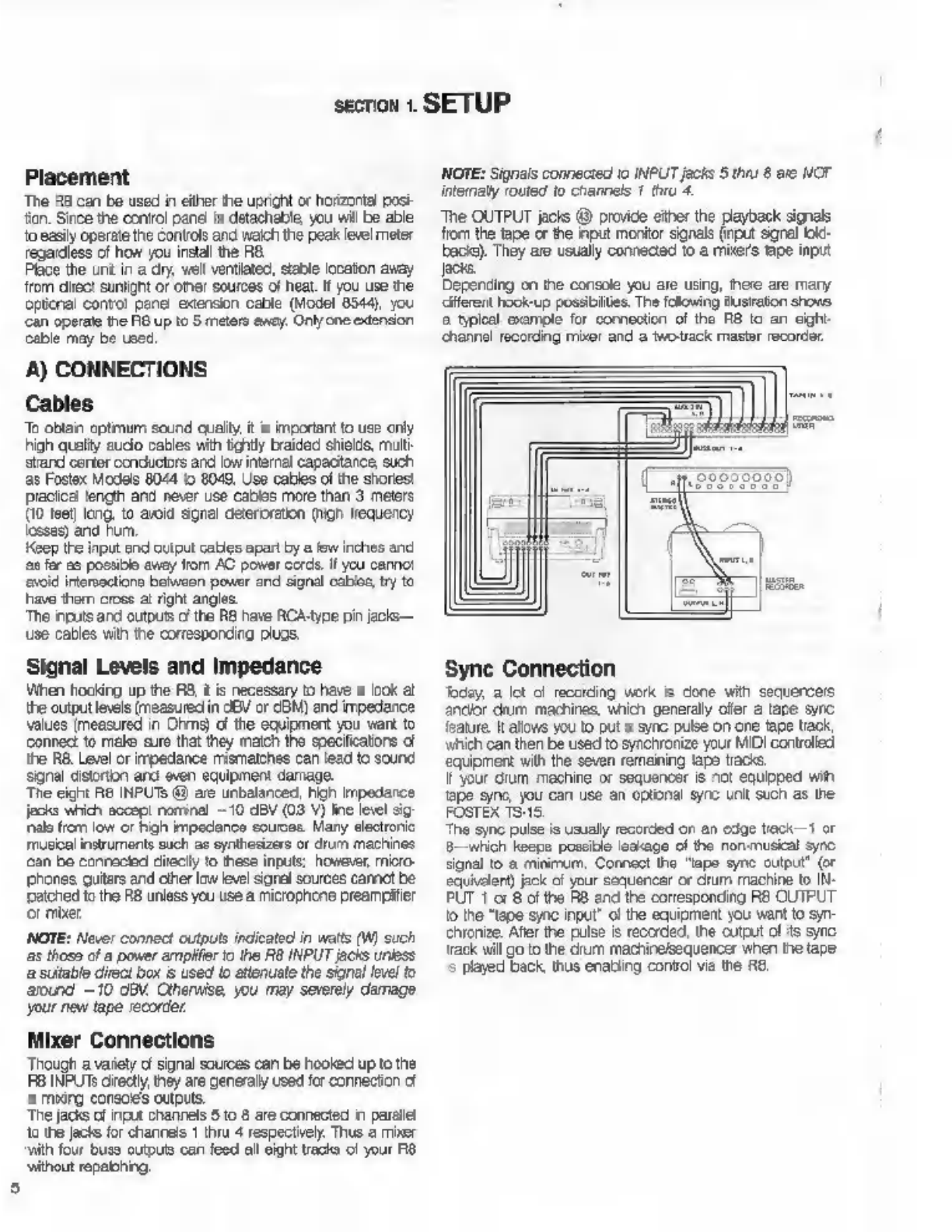
The
OUTPUT
jacks
@
provide
either
the
payback
signals
from
the
(аре
or
the
input
monitor
signals
(input
sanal
юс.
bacis).
They
are
usually
connected
to
a
mixers
tape
input
Jacks.
Depending
on
the
console
you
are
using,
there
are
mary
diferent
hook-up
possibilities.
The
folowing
ilusraton
shows,
а
typical
example
for
connection
of
the
FB
to
an
eight-
channel
recording
mixer
and
a
twotrack
master
recorder.
Sync
Connection
Today,
a
lot
c
recording
work
is
done
with
sequences
апејог
drum
machines,
which
generally
ofer
а
tape
sync
feature.
It
allows
you
to
put
a
sync
pulse
on
one
tape
track,
which
can
then
be
used
to
synchronize
your
MIDI
controlled
‘equipment
with
the
seven
remaining
tapa
tracks.
1
your
dum
machine
or
sequencer
is
not
equipped
wih
tape
sync,
you
can
use
an
optional
sync
unit
such
as
the
FOSTEX
1515
The
sync
pulse
is
usualy
recorded
on
an
edge
wack
—1
or
8—which
Кооро
possible
leakage
of
the
non-muscal
sync
signal
to
а
minimum.
Connect
the
"apo
sync
output”
(or
equivalent)
jack
o
your
sequencer
or
drum
machine
to
ÎN-
PUT
1
or
8
of
the
R8
and
the
corresponding
RB
OUTPUT.
to
the
“tape
sync
input"
о!
the
equipment
you
want
to
syn-
chronize.
After
the
pulse
is
recorded,
the
output
of
its
sync
track
will
go
to
the
drum
machine/sequencer
when
the
tape
5
played
back,
thus
enabling
control
ма
the
R8.
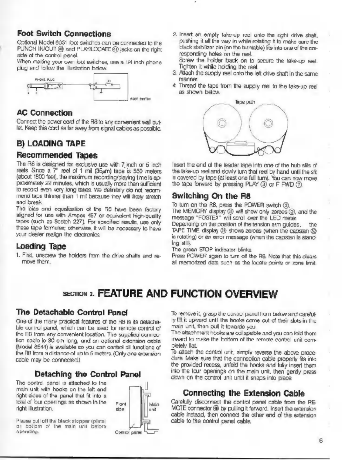
Foot
Switch
Connections
Optional
Model
8051
foot
switches
can
be
connected
to
пе
PUNCH
IN/OUT
@
and
PLAYILOCATE
@
jacks
on
the
right
задо
of
the
control
panel
When
making
your
own
со!
switches,
uso
a
1/4
inch
phone
рид
and
folio
the
illustration
below.
AC
Connection
Connect
the
power
cord
of
the
RBto
any
convenient
wall
out-
Те.
Keep
this
cord
as
far
ancy
from
signal
cables
as
possible.
B)
LOADING
TAPE
Recommended
Tapes
The
A8
is
designed
for
exclusive
use
vith
7,
inch
or
5
inch
reels
Snos
а
7"
reel
of
1
mi
(25m)
tape
is
550
meters
(about
1800
feet)
the
maximum
recording/playing
time
is
ap-
рехтаеј
22
minutes,
which
is
usually
more
than
sufficient
'o
record
even
very
long
takes
We
definitely
со
net
recom-
mend
tape
thinner
than
1
mil
because
теу
ми
кеу
stich
and
break
Tho
bies
and
equalization
of
the
АЗ
have
been
factory
aigned
for
use
wih
Ampex
457
or
equielent
high
quelty
tapes
(auch
as
Scotch
227),
For
specited
resuls,
use
only
these
tape
formulas;
otherwise,
it
wil
Ба
necessary
to
havo
your
dealer
realign
the
electronics
Loading
Tape
1.
First,
unscrew
the
holders
from
the
drive
shafts
and
re-
move
them.
section
2.
FEATURE
AND
The
Detachable
Control
Panel
One
of
the
many
pracical
features
cf
tne
RB
Is
ts
detacha-
le
corirol
panel,
which
can
be
used
for
remote
control
of
the
FO
from
any
convenient
location.
The
supplied
connec-
tion
cable
ie
30
cm
long,
and
an
optional
extension
cable
(Model
8544)
is
available
co
you
can
contiol
al
unctione
of
the
RB
from
a
distance
of
up
to
5
meters.
(Only
ore
extension
сабе
may
be
connected)
Detaching
the
Control
Panel
Те
conti
рото
o
etched
to
the
р
minut
d
hon
er
and
RON
sce
of
ho
pond
Va
ra
Mad
рото
ње
rou!
as
fant
sin
m
||
Ploaso
pull
off
the
black
stopper
(plato
or
родот
of
the
тат
unt
belore
i
operating
Consol
panel
h
2,
inet
an
empty
take-up
reel
onto
the
right
chive
shaf,
pushing
it
all
the
way
in
while
rotating
it
to
make
sure
the
black
stabilizer
pin
(on
the
turntable)
fts
into
one
of
the
cor
responding
holes
on
the
reel
Screw
the
holder
back
on
to
secure
the
take-up
res
Tighten
it
while
holding
the
reel
3
Allach
the
supply
reel
onto
the
let
orive
shaft
in
the
same
manner.
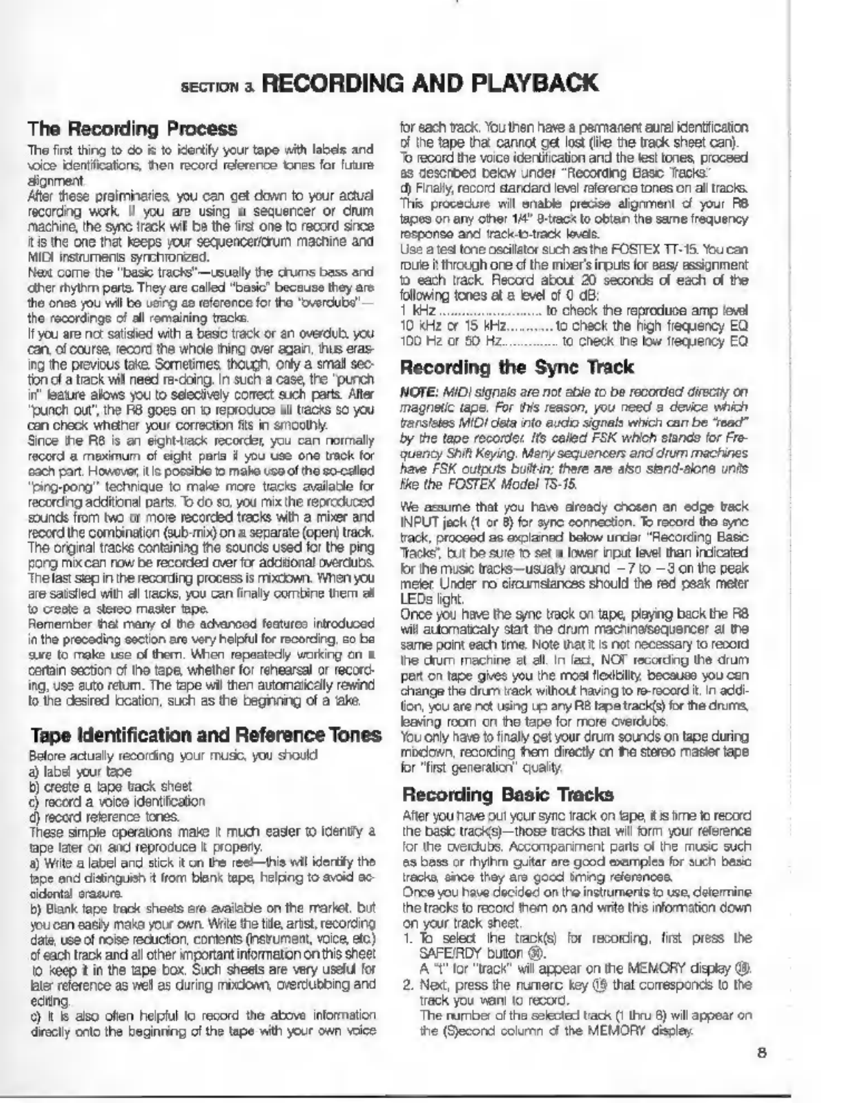
4.
Thread
the
tape
from
the
supply
reel
to
the
take-up
reel
as
shown
below.
pe
pan
Insert
the
end
of
the
leader
tape
into
one
of
the
hub
slits
cf
the
take-up
reel
and
sowly
turn
that reel
by
hand
until
the
sit
is
covered
by
tape
(at
least
one
full
turn).
You
can
now
move
the
tape
forward
by
pressing
PLAY
©
or
F
FWD
C
Switching
On
the
R8
To
turn
on
the
R8,
press
the
POWER
switch
(О)
The
MEMORY
display
@
vil
show
only
zeroes
(0)
and
the
message
"FOSTEX"
wil
scroll
over
the
LED
meter
Depending
cn
the
position
of
пе
tension
arm
guides,
the
TAPE
TIME
display
@
shows
zeroes
(when
the
capstan
@
is
rotating)
or
an
eror
message
(when
the
capstan
is
sland-
ing
aif
‘The
groon
STOP
indicator
Биле,
Press
POWER
again
io
turn
of
the
R8.
Nolo
that
his
cloare
al
memorized
data
such
as
the
locate
points
cr
zone
limit
FUNCTION
OVERVIEW
Te
removeit,
grasp
the
contol
pane!
пот
below
and
careful
ly
lit
it
upward
unti
the
hooks
come
out
of
their
slots
in
the
тат
unt,
thon
pul
it
toward
you.
The
attachment
nooks
are
collapsible
and
you
can
fold
thom
inward
to
make
the
boom
of
the
remote
control
unit
com
пев
fat.
То
attach
the
contiol
unt,
simoly
reverse
the
above
orcce-
dure
Male
sure
that
the
conrecion
cable
propery
fts
по
the
provided
recess,
unfold
the
hooks
and
fully
insert
them
into
the
four
opanings
on
ће
main
unt,
then
gently
press
down
оп
ne
control
unit
unt
t
snaps
into
place.
Connecting
the
Extension
Cable
Carefully
disconnect
the
control
panel
cable
from
the
ВЕ.
MOTE
connector
&
by
pulling
it
forward.
Insert
the
extension
cable
instead,
then
connect
the
other
end
of
the
extension
cable
to
the
control
panel
cable.

Basic
Tape
Transport
Functions
Before
actualy
recording
wih
your
now
НА,
tis
а
good
idea
to
get
acquainted
with
the
basic
tape
transport
funcions
frst.
‘The
à
records
and
pleys
back
at
38
cms
(15
inches
per
second).
This
high
speed
cneureo
very
low
wow
and
flute
and
a
high
signal-o-noise
ratio
Variable
control
of
the
tape
speed
is
possible
wih
the
PITCH
солна!
knob
@,
which
lows
you
to
increase
or
reduce
the
speed
by
1096
(пе
center
detented
positon
is
OFF).
Rewind/Fast
Forward/Play
‘The
two
transport
buttons
on
the
extreme
right
move
the
tape
at
high
speed—F.
FWD
@
in
the
direction
of
the
take-up
reel
(ovaro
the
sight),
and
REWIND
(8)
in
the
direction
of
the
Supply
reel
(toward
the
lef).
Continuing
to
presa
either
of
those
buttons
доне
down
the
wind
ороо
PLAY
G)
transports
the
tape
at
the
standerd
speed
(15
IPS)
from
let
t
right.
‘The
green
LEDs
above
these
buttons
light
up
to
show
which
transport
mode
is
currently
engaged.
Stop
Modes
Pressing
STOP
©
immediately
stops
any
tape
motion
and
the
transport
erters
the
standby
mode,
In
this
mode,
indicat
га
by
the
STOP
LED
©
on
conetanty,
the
pinch
roller
@
is
positioned
immediately
гохо
the
rotating
capstan
@
so
hat
ine
RB
can
stat
to
play
right
away
as
soon
as
the
PLAY
button
is
pressed.
1
you
hold
down STOP
for
longer
than
half
a
second,
the
transport
mechanism
is
released,
making
it
easier
to
edit
tape,
ас.
This
Release
Mode
is
indicated
by
the
STOP
LED
blinking.
YOU
can
return
to
Standby
Mode
by
shorty
pressing
STOP
адап
(LED
changes
from
blinking
to
on)
Iis
possible
to
enter
апу
transport
mode
from
either
Standby
or
Roloase
STOP
modos.
However,
опоѓла
playback
from
the
release
mode
takes
longer
since
the
pinch
roler
is
turer
from
the
capstan.
When
you
do
rot
intend
to
play
or
record
for
a
while.
its
a
gocd
idea
to
let
the
tension
arm
guides
(8)
crop
to
their
lowest
position
by
rotating
ether
reel
by
hanc
to
slacken
the
ape.
This
action
stops
the
capstan
motor,
thus
reducing
wear
оп
the
capstan
bearing
for
а
longer
service
lle
Before
using
the
tape
transport
controls,
again
apply
tension
to
the
tape
to
re-start
the
capstan
motor
When
ling
the
tension
arm
guides
drop
in
thie
manner
dur
ing
Standby
Мода
ths
mode
є
automatically
ested
and
the
STOP
LED
gants
to
bink
indicating
Release
Mode.
An
error
message
appears
on
the
TAPE
TIME
display.
Advanced
Computer-Controlled
Functions
The
А8
offers
a
number
of
helpful
computer-corirollec
trans-
port
features
They
are
introduced
here
to
ive
you
an
idea
‘of
how
you
can
make
the
recording
and
playback
process
described
below
even
easier.
1
you
want
1o
use
some
of
these
functions
right
away,
you
сап
of
course
read
about
ADVANCED
FEATURES
(pege
13)
before
going
on
the
nex
section,
(Only
the
operaion
а
locate
0
is
cesoribed
hero).
ај
Preroll
Allows
youto
stat
the
tape
automatically
several seconds
be-
fore
the
zero
position
or
а
memory
point.
This
feature
is
very
pracical
for
overdubbng,
because
you
can
hear
a
few
sec-
Onds
of
musc
before
your
cue
point,
making
it
easier
to
‘come
in
with
the
correct
timing.
b)
Locate
0
This
function
automaticaly
retums
the
tape
to
the
zero
posi-
tion
on
the
TAPE
TIME
counter
‘Simply
press
the
LOCATE
0
button
€)—the
АВ
wil
rewind
ог
fast
forward
as
necessary,
with
the
green
LOCATE
0
9
indicator
И.
When
tha
zero
positon
is
reached,
the
tape
stops
and
this
indicator
goes
out
NOTE:
Locate
О
wil
not
work
when
zore
linit
is
set
and
the.
zero
TAPE TIME
position
is
outsice
of
the
designated
zone.
€)
Locate
‘The
RB
lets
you
set
up
to
10
diferent
memory
points,
which
сап
be
automatically
located
with
this
tuncion.
d)
Auto
Play
Used
in
combination
with
locate,
locate
0
or
auto
retum,
tnis
funcion
automatically
starts
playback
сї
the
tapa
whenever
а
memory
point
or
the
zero
posiion
is
reached.
When
combined
wth
auto
retum.
the
RB
will
repeatedly
рау
the
designated
section
of
the
tape
until
stopped
(“shuttle
playback’
*)
Auto
Retum
This
ваше
automatically
гөште
the
tape
to
an
adjustable
“saring
point”
whenever
а
designated
“ending
pont"
is
reached.
1)
Zone
Limit
Lats
you
specify
a
desired
section
[zone
of
the
tapo,
to
"which
all
transport
functions
such
as
play
or
rewind
will
be
limitec—the
tape
wil
automatically
stop
when
the
beginning.
ог
the
end
0
the
zone
is
reached
This
feature
is
useful
when
working
on
a
specific
section
of
a
tape
9)
Tape
неа!
Zone
Limit
Smit
to
the
preceding
tunction,
here
the
entire
tape
is
the
"zone"
The
RB
can
be
programmed
1o
stop
automatically
whon
the
end
or
beginning
of
a
tape
is
approached
during
rewind
or
fast
forward.
This
feature
prevents
the
tape
frem
ac-
cidentaly
coming
of
the
reels.
section
з
RECORDING
AND
PLAYBACK
The
Recording
Process
Tho
first
thing
to
do
is
to
identify
your
tape
with
labels
and
voice
identifications,
then
record
reference
tonas
for
future
alignment,
Afer
these
preliminaries.
you
can
get
down
to
your
actual
recording
work
II
you
are
using
a
sequencer
or
drum
machine,
he
sync
track
wil
be
the
firs!
one
to
record
since
itis
the
оле
that
Keeps
your
sequencercrum
machine
and
MIDI
instruments
synchronized.
Next
come
the
"basic
racks"
—
usually
the
drums
bass
and
«ther
rhythm
parts,
They
are
called
"basic"
because
they
are
the
onea
you
will
bo
usirg
co
reference
for
the
"overdubs"
—
the
recordings
of
all
remaining
tracks.
I
you
are
no:
satisied
with
a
basic
track
or
en
overdub
you
can.
of
course,
record
the
whole
thing
over
again,
hus
eras-
ing
the
previous
take.
Sometimes,
though,
only
a
small
sec-
ton
of
a
track
will
need
re-doing.
in
such
a
case,
the
"punch
in’
feature
alovs
you
to
selectively
correct
such
parts.
After
"punch
out’,
the
RB
goes
on
10
reprocuce
а!
tacks
so
you
сап
check
whether
your
correction
fs
in
smoothly
Since
the
RB
is
an
eight-ack
recorder,
you
can
normally
record
a
maximum
of
eight
paris
i
you
use
one
track
for
cach
рап.
Howover
itis
possible
to
make
use
of
the
so-called
“ping-pong”
technique
to
make
more
tracts
available
for
recording
additional
parts.
70
do
so,
you
mix
Пе
reproduced
sounds
from
two
or
more
recorded
tracks
with
a
mixer
and
record
the
combination
(виб-ті)
on
a
separate
(open)
track.
‘The
orginal
tracks
containing
the
sounds
used
for
the
ping
gong
mik
can
now
be
recorded
over
for
additional
overdubs.
‘he
last
вер
in
he
recording
process
is
mixcown,
When
you
re
satslled
with
all
racks,
you
can
finaly
combine
them
al
to
creste
а
stereo
master
ape.
Remember
hat
many
of
tho
advancod
foaturoo
introducod
in
the
preceding
section
aro
very
helpful
for
recording,
со
be
sure
to
rake
use
of
them.
When
repeatedly
working
on
a
Certain
section
of
the
tape,
whether
for
rehearsal
or
record-
ing,
use
auto
retum.
The
tape
wil
then
automatically
rewind
1o
the
desired
location,
such
as
the
beginning
of
a
‘ake.
Tape
Identification
and
Reference
Tones
Belore
actually
recording
your
music,
you
should
a)
label
your tage
b)
creste
а
tape
track
sheet
€)
record
a
voice
identification
d)
record
геіегепсе
tones.
These
simple
cperatons
make
t
much
easier
to
idently
а
"ape
later
ог
and
reproduce
it
propery.
a)
Wile
а
label
and
stick
it
on
the
ree
this
wil
identity
the
tage
and
distinguish
t
from
blank
tape,
hoping
to
avoid
ac
дво!
erasure.
5)
Blank
tape
track
shoats
are
available
on
the
market,
but
you
сап
easily
make
your
own.
Write
the
tile,
artst,
recording.
date,
use
of
noise
recuctor,
contents
(nsrument,
voce,
etc)
of
each
track
and
all
other
important
information
on
this
sheet
to
keep
t
in
the
tape
box.
Such
sheets
are
very
useful
for
later
reference
as
well
as
during
mixdiown,
overdubbing
and
ediino.
9
1
6
also
often
helpful
to
record
the
above
information
directly
onto
the
beginning
of
the
tape
with
your
own
voice
for
each
track,
You
then
have
a
permanent
aural
identification
of
the
tape
that
cannot
get
lost
(ike
tne
track
sheet
сап).
To
record
the
voice
icentitication
and
the
test
tones,
proceed
as
described
below
under
"Recording
Base
Tracks”
4)
Finally,
record
standard
level
reference
tones
on
all
tracks.
This
procedure
will
enable
precise
alignment
o
your
P8
tapes
on
any
other
14"
G-tacx
to
obtan
the
same
frequency
response
and
tracktb.track
lavas.
Use
a
tes
tone
oscilator
such
as
the
FOSTEX
TT-18
You
can.
Toute
i
through
ore
d!
the
mber'
при
for
easy
assignment
tb
each
track.
Record
about
20
seconds
of
each
of
the
following
tones
at
а
level
of
0
dB:
1
kHz
enses.
0
Check
the
reproduce
amp
level
10
kHz
or
15
kHz.
to
check
the
high
frequency
EQ
100
Hz
or
50
Hz
to
check
the
low
frequency
EQ
Recording
the
Sync
Track
NOTE:
MID}
signals
are
not
able
to
be
recorded
directly
on
magnetic
tape.
For
this
reason,
you
need
a
device
which
ransleles
MIDI
dela
into
audio
signals
which
can
be
"read"
by
the
tape
recorder.
[ts
called
FSK
which
stands
for
Fre-
quency
Shit
Keying,
Mary
sequencers
and
drum
machines
have
FSK
outputs
builtin:
there
are
also
stand-alone
units
tke
the
FOSTEX
Model
15-15.
Ме
assume
that
you
have
already
chosen
an
edge
track
INPUT
jack
(1
or
8)
for
sync
connection.
To
rocord
tho
syre
track,
proceed
as
exolained
below under
"Recording
Basic
“Tacks,
but
be
sure
го
set
a
lower
при
level
than
indicated
for
the
music
tracks—usualy
around
~7
to
-
3
on
the
peak
meter.
Under
по
circumstances
should
the red
peak
meter
LEDs
light.
Once
you
have
the
syne
track
on
tape,
playing
baok
the
R8
wil
automatcaly
start
те
drum
mactinelsequencer
а!
the
same
point
each
tme.
Note
that
iis
not
necessary
to
record
the
dum
machine
at
all
In
fad,
NOT
recording
the
drum
part
on
tape
gives
you
the
most
ilexitiliy,
because
you
can
change
the
drum
track
without
having
to
re-record
it,
In
addi-
tion,
you
are
net
using
up
any
RB
tape
track(s
for
the
drums,
leaving
room
cn
the
tape
for
more
overdubs.
You
only
have
to
finaly
cet
your
drum
sounds
on
tape
during
midon,
recording
them
directly
сп
ће
stereo
master
tape
for
"first
generation”
quail
Recording
Basic
Tracks
After
you
neve
out
your sync
track
on
tape,
itis
ime
to
record
the
basic
tracks)
those
tracks
that
wil
form
your
reference
for
the
overdubs.
Accormparirment
parts
of
the
music
such
as
bass
or
thyhm
guitar
are
good
examples
for
such
basic
каско,
since
they
aro
gocd
img
references.
Once
you
have
decided
on
the
instruments
о
use,
determine
the
tracks
to
record
them
on
and
write
this
information
down
оп
your
track
sheet.
1.
To
select
the
track(s)
for
recording,
first
press
the
SAFEIRDY
button
49.
A
"t"
for
"track"
vil
appear
on
the
MEMORY
display
(9.
2.
Мек,
press
the
numerc
key
46
that
corresponds
to
the
Tack
you
want
to
record,
The
number
of
the
selected
tack
(!
thru
8)
will
appear
on
the
(Second
column
of
the
MEMORY
display.
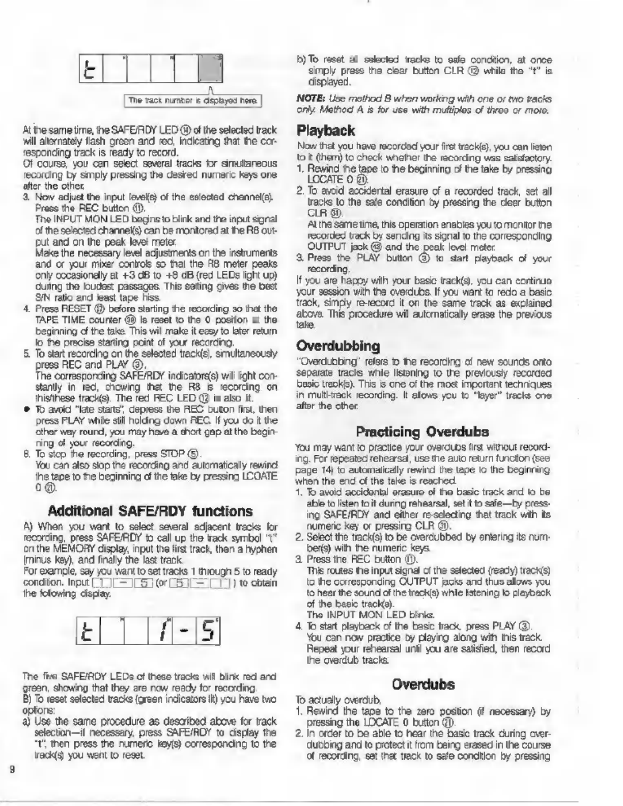
Е
[Tre
wack
rumor
&
aspayed
here
]
Atihesametime,
the
SAFEIRDY
LED
@
of
the
selected
track
wil
alernately
flash
green
and
rec,
indicating
that
the
cor-
responding
track
is
ready
to
record.
Of
course,
you
can
select
several
tracks
for
simultaneous
'ecording
by
simply
pressing
the
desrec
numeric
keys
one
after
the
other
8.
Now
adjust
tho
input
levele)
of
the
selected
channel(s}
Press
the
REC
button
(9),
The
INPUT
MON
LED
beginsto
blink
and
the
input
signal
of
the
selected
channels)
can
be
monitored
at
he
ВВ
out-
put
and
on
the
peak
level
meter
Make
the
necessary
level
adjustments
on
the
instruments
and
or
your
mixer
controls
so
thai
the
R8
meter
peaks
опу
occasionally
at
+3
dB
to
+8
dB
(red
LEDs
ight
up)
during
the
loudest
passages,
This
seting
gives
По
best
SIN
ratio
and
least
tape
hiss
4,
Press
RESET
@
before
starting
the
recording
so
that
the
TAPE
TIME
counter
Gi)
јо
reset
to
the
0
position
at
the
beginning
dl
the
take.
This
wil
make
it
esy
to
kater
retum
Јо
the
precise
starting
point
of
your
recording.
5
To
start
recording
on
the
selected
track(s),
smultaneousy
press
REC
and
PLAY
(9:
The
corresponding
SAFEIRDY
indicatores)
wil
light
con-
stay
in
red,
chowing
that
the
RB
B
recording
on
thistthese
track(s).
The
red
НЕС
LED
@
is
also
it
©
To
avoid
"late
stans”,
depress
the
REC
buton
first,
then
press
PLAY
while
stil
holding
down
БЕС.
If
you
do
ќ
the
‘ther
way
round,
you
may
have
a
shot
gap
at
the
begin
ning
of
your
recording,
8.
To
stop
the
recording,
press
STOP
(9.
You
can
also
stop
the
recording
and
automatically
rewind
дар
omis
delis
i
pesi
LCOATE
Additional
SAFE/RDY
functions
A)
When
you
want
to
select
several
adjacent
tracks
for
recording,
press
ЗАРЕЛОУ
to
call
up
the
rack
symbol
"I^
оп
the
MEMORY
display,
input
the
first
track,
then
a
hyphen
[minus
key),
and
finally
the
last
track.
For
example,
say you
want
to
sel
racks
1
through
5
to
ready
conditor.
при
1
J|
—
LG
0r
L5
L—
77)
to
obtain
he
folowing
display.
t
The
five
SAFEIRDY
LEDs
ofthese
trac
vill
Birk
red
and
grean,
showing
that
they
are
now
ready
for
recording.
B)
To
reset
selected
tracks
(green
indicators
Н)
you
have
мо
options:
a)
Use
the
same
procedure
as
described
above
for
track
selection—if
necessary,
press
SAFE/RDY
to
display
the
"t
then
press
the
numeric
кеу)
corresponding
to
the
acis)
you
want
to
reset
Б) To
reset
al
solocted
iracks
to
safe
condition,
at
once
simply
press
the
clear
button
CLR
@
while
the
"t"
is
displayed.
NOTE:
Use
method
B
when
working
with
one
or
two
tacks
only.
Method
А
is
for
use
with
multiples
of
throo
or
moro.
Playback
Now
that
you
have
recorcod
your
fret
track),
you
can
listen
to
it
(hem)
to
check
whehe!
the
recording
was
satisfactory.
1.
Rewind
ће
tape
го
the
beginning
of
the
take
by
pressing
LOCATE
0
8).
2.
То
avoid
accidertal
erasure
of
a
recorded
track,
set
all
tracks
to
the
safe
condition
by
pressing
the
dlear
button
CLR
89.
At
ihe
same
time,
this
operation
enables
you
to
montor
пе
recorded
track
by
sending
its
signal
to
the
corresponding
OUTPUT
jeck
@
and
the
peak
level
mete:
8.
Press
the
PLAY
button
@
to
dar
payback
of
your
recording
If
you
are
happy
wih
your
base
track(s)
you
can
continue
your
session
with
the
overdubs
If
you
want
to
redo
a
basic
Track,
simply
re-record
it
on
the
same
track
as
explained
above.
This
procedure
wil
automaticaly
erase
the
previous
tate,
Overdubbing
“Qverdubbing’
refers
о
те
recording
of
new
sounds
onto
separate
tracks
whle
listening
to
the
previously
recorded
basic
track's).
This
is
one
of
the
most
important
techniques
in
multitrack
recording.
It
allows
you
to
"layer"
tracks
one
after
the
other
You
may
want
to
practice
your
overdubs
tr
wihout
record-
ing.
For
repeated
renearsal,
use
tie
auto
return
funcion
(see
раде
14)
to
eutomafcelly
rewind
the
tape
ю
the
beginning
when
the
end
of
the
teke
is
reached,
1.
To
avoid
accidental
erasure
of
tno
basic
track
and
fo
be
able
to
[sten
to
it
during
rehearsal,
st
t
to
safe
by
press
ing
SAFE/RDY
and
either
re-sdecing
that
track
wih
ils
numeric
key
or
pressing
CLR
9,
2.
Select
the
track(s)
to
be
overdubbed
by
entering
15
num-
ber)
with
the
numeric
keys.
3.
Press
the
НЕС
bution
©.
This
routes
the
input
signa
ofthe
selected
(ready)
racks)
io
the
corresponding
CUTPUT
acs
and
thus
allows
you
to
heer
the
sound
ofthe
tracks)
while
Istening
to
playback
of
ho
basic
track).
The
INPUT
MON
LED
шти.
4.
To
start
playback
of
the
basic
track,
press
PLAY
(3)
You
can
now
practice
by
plajirg
along
with
tis
пск
Repeat
your
rehearsal
unt!
you
are
salised,
then
record
the
сета
tracks
Overdubs
To
actually
overdub,
1.
Rewind
the
tape
to
the
zero
position
(f
necessary)
by
pressing
the
LOCATE
0
button
(0).
2.
in
order
to
be
able
to
hear
ће
basic track
during
over-
dubbing
and
to
protect
it
from
being
erased
in
the
course
of
recording,
set
та!
tack
to
safe
сопацол
by
pressing
SAFERDY
end
then
the
corresponding
numeric
key
з.
Input
ће
numbers
of
the
tracks
you
want
to
overdub
with
the
numeric
keys.
4.
Press
REC
to
monitor
the
input
signal
on
the
peak
level
meter,
and
adjust
the
instrument
ог
mixer
level
so
that
the
RB
meter
peaks
only
occasionally
&
43
dB
to
+8
dB
for
the
track(s)
о
be
recorded.
The
INPUT
MON
LED
links
5
When
you
are
ready
to
begin
recording,
press
the
REC
end
PLAY
buttons
simutanecusy
Flay
along
with
the
sound
of
the
basic
track
MOTE:
if
you
are
cverdubbing
via
a
live
microphone,
you
will
need
io
monitor
the
basic
track(s)
via
headphones.
8.
Il
yeu
are
using
the
ашо
return
function
[p
14),
ће
tape
will
stop
auiomaticaly
at
the
end
of
the
‘ake
and
be
rewound.
Otherwise,
end
the
recording
by
pressing
the
STOP
button
©
You
cen
now
repeat
this
process
as
often
as
necessary
to
омеа
all
your
каско,
И
you
ае
recording
a
total
of
more
an
eight
parts,
you
wil
have
to
"open
up”
tracks
by
using
the
ping-pong
furction
explained
below.
Punch
In/Out
Occasionally
a
recording
is
amos
perfect
except
for
a
mis-
lake
oF
wo.
Instead
of
revecording
the
entre
track,
the
purch
inout
procedure
lets
you
selecively
correct
such
un
salidactory
mistakes
without
having
to
redo
ovorything
oleo
ас
wel
's
трогап
to
note
however
that
timing
is
critical
here.
If
you
punch
10
early
ог
punchou
too
lale,
you
could
wreck
the
very
thing
youre
trying
to
fix.
For
ths
reason,
its
bes
to
fird
a
phrese
or
a
seciion
that
surrounds
the
mistake
and
punchinfout
at
одеа
points
Ike
downbeats
Purch
in/out
cen
be
performed
by
hand,
but
it
s
more
prac-
'Ca
to
use
the
optonal
foot
switch
connected
to
the
PUNCH
IN/OUT
jack
@.
f
you
аге
both
performer
and
recording
engineer
Rehearsal
Mode
You
сап
practice
punch
in
and
out
using
а
connected
foot
switch,
in
order
to
get
used
to
the
timing
ard
ensure
a
per
Ба
punch
fet
"Whle
nolding
down
the
record
buton
REG,
зер
on
the
foot
sic
The
orange
REC
indicator
@
wil
stat
to
blink,
showing
that
renearsal
mode
has
been
entered.
2.
Select
the
кас)
you
wish
to
punch
inout
on
wih
SAFE/ROY
anc
the
numere
keys.
The
SAFE/RDY
indicators
cf
these
tracks
will
blink
red
ard
green.
3.
Rewind
to
a
location
prior
to
the
punchrin
point,
then
press
PLAY
to
stert
playback
4.
Whan
you
reach
the
punch
in
point,
sep
on
the
foot
switch
This
operation
switches
the
monitor
fiom
tape
mode
го
input
mode,
meaning
you
will
hear
the
sound
from
the
recorded
reci)
you
want
to
correct
untl
the
foot
switch
ig
preseed,
and
thon
tho
signal
prosont
at
tho
elected.
INPUT
track(s)
(i.
the
sound
you
are
playing
live)
5
Step
cn
the
foct
switch
again
when
you
reach
the
end
of
the
passage
to
be
re-recorded,
in
order
to
punch
ом.
This
‘operation
cwilchoo
the
monitor
back
to
tape
mode
со
you.
‘can
once
again
hear
tho
previous
recording,
In
other
words,
repeatedly
pressing
the
foot
switch
allows
you
to
toggle
between
tape
monitor
and
input
manitor
on
the
selected
trachs).
There
are
two
important
reasons
for
this
rehearsal.
First,
you
must
match
the
recording
levels
о
the
track
(pre-
recorded}
and
the
"ње"
part
(о
bo
recorded).
Second,
you
musi
такт
the
fee!
end
phrasing
so
that
when
you
punctvout,
4
sounds
like
a
single
performance.
6.
To
салсе
the
rehearsal
mode,
press
the
REC
buton
and
at
the
same
time
step
оп
the
foot
owitoh.
Actual
Punch
In/Out
1.
Rewind
the
tape
to
a
location
prior
to
the
panch-n
point.
2.
Select
the
track(s)
you
wish
to
punch
inout
on
wth
SAFEIRDY
and
the
numeric
keys.
The
SAFE/RDY
indicators
of
these
tracks
wil
lash
red
and
green
з.
Press
the
PLAY
button
to
start
playback
4,
Wren
you
reach
the
punch
in
point,
press
PLAY
and
REC
at
the
seme
time
it
you
are
using
a
foot
switch
connected
to
the
PUNCH
INOUT
ack,
you
сап
step
on
the
foot
swich
instead.
You
can
now
record
your
пем
part
over
the
previous
mis-
take,
thereby
correcing
it
5
To
punch
out,
hold
down
the
PLAY
button
and
simuitane-
ously
tap
STOR
И
you
are
using
а
foot
switch,
step
on
й
instead.
Either
procedure
ends
the
punch-out
recording
without
stooping
playback
of
the
tape
on
а!
tracks,
so
that
you
immediately
know
whether
your
punch-out
was
smooth,
Of
course,
you
can
also
end
the
punchvout
by
smply
pressing
the
STOP
bution
to
stop
the
tape.
еї
you
press
the
STOP
button
for
more
than
haf
a
second
while
holding
down
PLAY,
the
tape
will
also
top.
Ping-Pong
Recording
Also
referred
to
as
“bouncing
tracks’,
ping-oonging
is
‘another
important
multi-track
technique.
Duing
the
ping
pong
procedure,
several
isting
tracks
are
played
back,
mixed
into
one
track
and
at
the
same
fime
re-recorded
on
ап
open
track,
which
makes
the
original
tracks
avalable
for
subsequent
overdubs.
The
ping-pong
procedure
may
Бе
repeated
indefintely
in
theory;
but
in
practice,
more
than
woe
is
usually
not
sonically
pleasing
Another
version
of
the
ping-pong
technique
leis
you
mix
спе
ог
more
ive
sources
wih
several
exising
tracks,
at
the
same
time
recording
the
mix
on ап
avaliable
track.
To
combine
the
playback
(and
Ive)
sounds
for
the
ping-
pong,
а
mixer
is
necessary,
See
the
manual
с
your
console
for
detalla
on
mixing
for
ping
pong
recording.
NOTE:
Notalltracks
are
equally
suitable
for
bouncing.
И
you
record
on
a
tack
adjacent
io
the
one
you
are
mixing
from
(for
example,
track
2
=
3
—
4),
leakage
in
пе
record/play
head
could
cause
feedback.
Therefore,
ty
to
avoid
ping-
pong
recerdngs
between
neighboring
tracks
whenever
possible.
If
ping-pong
to
an
adjacent
track
is
absolutely
necessary.
you
may
have
to
lower
the
levels.
1.
Make
sure
the
tracks
you
want
to
transer
wit
the
ping-
10

и
pong
аге
set
to
Safe
condition
(CAFE/RDY
indicators
greon).
The
track
you
want
to
bounce
(the
destination
track)
must
ре
Ready
for
ecorcing
(SAFE/RDY
LED
flashes
red
and
green).
2.
To
adsl
the
mixed
level
а
the
ping-pong
tracks
on
your
mixer,
make
а
preliminary
recording
while
watching
the
peak
meter
for
the
destination
track.
3.
Rewind
to
the
beginning
чип
LOCATE
0
and
record
чип
the
appropriate
level
settings-
Bear
in
mind
that
once
you
complete
a
ping-pong
procs-
dura,
that
sub-mix
wil
bo
treated
ава
sndle
element
in
the
final
midown.
Cuing
‘This
practical
feature
lets
you
search
for
the
enc
or
beginning
of
a
recording
at
high
speed,
in
either
fast
forward
or
rewind:
mode.
The
RB
has
a
lifter
mechanism
which
normally
litis
the
tape
away
from
the
head
in
these
modes
in
order
го
prevent
ос
esse
head
wear
This
mechanism
can
be
defeated
wih
the
cue
function,
thus
allowing
you
to
Isten
to
the
tape
at
fieh
преод
io
detect
a
euo
poh
1.
Holding
down
the
fast
forward
buton
F
FWD
@
ог
the
REWIND
(9)
button
and
tap
the
PLAY
button
(3)
orce.
Ав
soon
as
you
release
F
FWD
or
REWIND,
the
cuing
mode
is
entered
and
the
sound
can
be
montored
from
the
outputs
and
on
the
peak
level
meter
Once
in
the
cuing
mode,
you
can
switch
the
direction
of
the
tape
(while
sili
monitoring
1)
by
pressing
F
FWD
or
REWIND,
You
can
also
lower
the
tape
speed
by
noding
these
but-
ione,
making
it
easier
to
detect
the
desired
locaton.
2.
To
oxi
from
thie
mode,
proce
STOP
cr
PLAY.
Kis
also
possible
to
stop
cuing
by
smultaneousy
pressing
F
PWD
or
REWIND
and
the
PLAY
button
Mixdown
This
is
the
process
whereby
the
signals
from
the
tracks
of
your
R8
are
remixed
on
your
mixer
to
make
a
stereo
master
tape.
You
wil
need
г
mixing
console
and
а
two-track
master
recorder
to
make
a
mixdown
recording.
As
lar
as
the
R8
is
concerned,
mixiown
is
basically
just
normal
playback—al
important
operations
wil
be
carried
out
оп
your
mixer
1.
Make
sure
tat
all
tracks
o!
the
RB
are
in
saie
concition—
all
SAFEIRDY
indcators
@
must
be
green.
The
master
record
should
be
reacy
Ð
record.
2.
Start
recording
wih
the
mester
recorder,
and
press
the
ВВ
PLAY
button
to
reproduce
all
tracks.
Using
a
Synchronizer
A
synchronizer
such
as
the
Fostex
Model
4030
can
be
con-
nected
to
the
SYNCHRONZER
terminal
&
for
control
ofthe
на.
SMPTE
time
code
is
normaly
recorded
on
an
edge
tack,
Usually
track
1
or
8.
Keep
the
recording
level
to
about
—7
10
—
Son
the
R8
peak
meter
SMPTE
ime
cade
must
always
o
recorded
in
one
continuous
pass.
Creative
Use
of
the
Pitch
Control
The
PITCH
control
can
be
used
during
recording
or
pley-
back.
Normally
these
operations
shoud
be
done
with
PITCH
centered
far
two
reasons.
(a)
lapes
ans
made
at
calibrated
‘speeds,
and
(b)
the
record/play
equalization
and
the
Dolby
Greuity
are
properly
aligned
only
at
fne
normal
running
speed.
There
areinstances
when
ciferert
speeds
are
useful
Retiming
Ға
recording
has
been
made,
say
for
a
60-second
advertise-
ment,
and
the
overall
program
is
а
few
seconds
too
short
ог
too
long,
the
PITCH
control
can
be
used
during
remixing
to
adjust
the
overall
play
ime.
The
shift
up
or
down
in
the
fre-
quency
of
the
program
should
not
be
disturbing
so
long
as.
а
relatively
small
correction
is
used,
say
less
than
5%
(less.
than
naf
пе
maximum
speed
deviaion).
A
5%
speed
change
on
a
60
second
tape
wil
add
or
subtract
3
seconds.
"n
a
longer
program,
sey
a
20
minute
segment
а
5%
change
in
length
wil
amount
to
a
full
minute.
Retuning
Suppose
tre
initial
tack
is
recorded
with
tho
performer
out
ониге.
During
subsequent
overdubs,
it
may
bo
impractical
ог
impossible
to
retune
the
instruments
to
match
the
de-
tuned
orginal
rack.
In
this
case
adjust
the
PITCH
control
up.
‘or
down
so
thet
the
playback
pitch
ecuals
the
pitch
ofthe
in-
strument
which
cannot
be
retuned.
Then
make
the
overdub
at
that
speed.
Subsequent
overdubs
andlor
the
mixdown
сап
be
done
ether
at
standard
speed
or
the
modiied
speed,
as
desred
Speeding
up
a
Performance
without
Changing
the
Pitch
When
a
performer
wishes
to
рау
a
complex
passage
at
a
tempo
that
would
normally
be
cific
not
beyond
his
abi
ту,
the
FITCH
солто!
can
ре
put
lo
good
use
The
lechniqueis
best
used
during
an
overdub
where
atleast
опе
recorded
track
is
available
for
a
frequency
reference.
Whon
making
the
overdub,
cot Ine
PITCH
contro}
со
it
lows
down
the
tape
(rotate
CCW).
The
performer
then
plays
in
tempo
with
the
срма
down
tape.
During
this
operation,
be
sure
the
instrument
is
tuned
to
the
lower
pitch
heard
in
the
monitors
For
payback,
return
the
PITCH
control
to
the
normal
setting
(centered).
The
overdub
will
now
be
heard
in-tune,
at
normal
pitch,
and
at
a
fester
tempo
than
t
was
actualy
performed.

SECTION
1.
Once
a
tape
has
been
recorded,
È
may
be
necessary
to
rearange
the
order
of
some
takes,
spice
two
diferen:
reels
«f
tape
одоРет
ox
te
add
leader
tape
botwoon
takos
on
а.
given
tape.
Al
these
operations
are
considered
to
be
editing.
То
edit
a
tape.
one
should
have
the
folowing
materiais
avaiable:
1
А
splicing
block.
Such
as
Fostex
Model
9930.
This
is
Usually
made
of
aluminum,
with
a
groove
to
hold
the
taoe,
and
оге
or
more
grooves
cut
across
the
епот
ot
the
Боск
to
guide
the
cutter
2.
A
sharp,
normagneto
single-edged
razor
blade.
To
be
sure
the
даде
has
no
residual
magnetism,
I
can
be
dernagnetzed
in
much
the
same
way
thet
the
head
as-
sembly
is
demeanetized.
Be
sure
to
hold
the
blade
se-
су,
honever
since
a
demegnetizer
may
ри!
stongly
‘on
the
biede.
NOTE:
A
magnetzed
razor
blade
will
cause
an
audible
чи"
or
‘pop’
at
the
point
of
the
splice
Do
not
use
scissors.
EDITING
з
A
sharp
white
or
yellow
grease
pencil
to
mark
the
intenc-
ед
splice
point
on
the
back
of
the
tape.
4.
A
rol
of
122"
wide
(12
om)
splicing
tape.
Splicing
tape
is
specally
manufacturad
for
joining
magnetic
tape;
it
is
thin,
and
has
an
adhesive
that
wil
adhere
to
the
tape
backing,
yet
not
seep
out
of
the
splice
under
the
typical
pressures
and
temperatures
encountered.
CAUTION:
Noor
uso
conventional,
colophano
tapo
or
packaging
tapes
for
splicing.
Some
of
the
adhesive
on
such
tapes
may
Uttrretely
contaminate
the
recording
tape,
and
rey
leeve
deposits
on
the
tape
heads
and
guides
5.A
supply
of
plasic
or
paper
leader
tape:
plastic
is
stronger
but
paper
is
easier
to
wrle
upon
wih
a
pon
or
pendi,
and
is
thus
handy
for
making
notes.
12
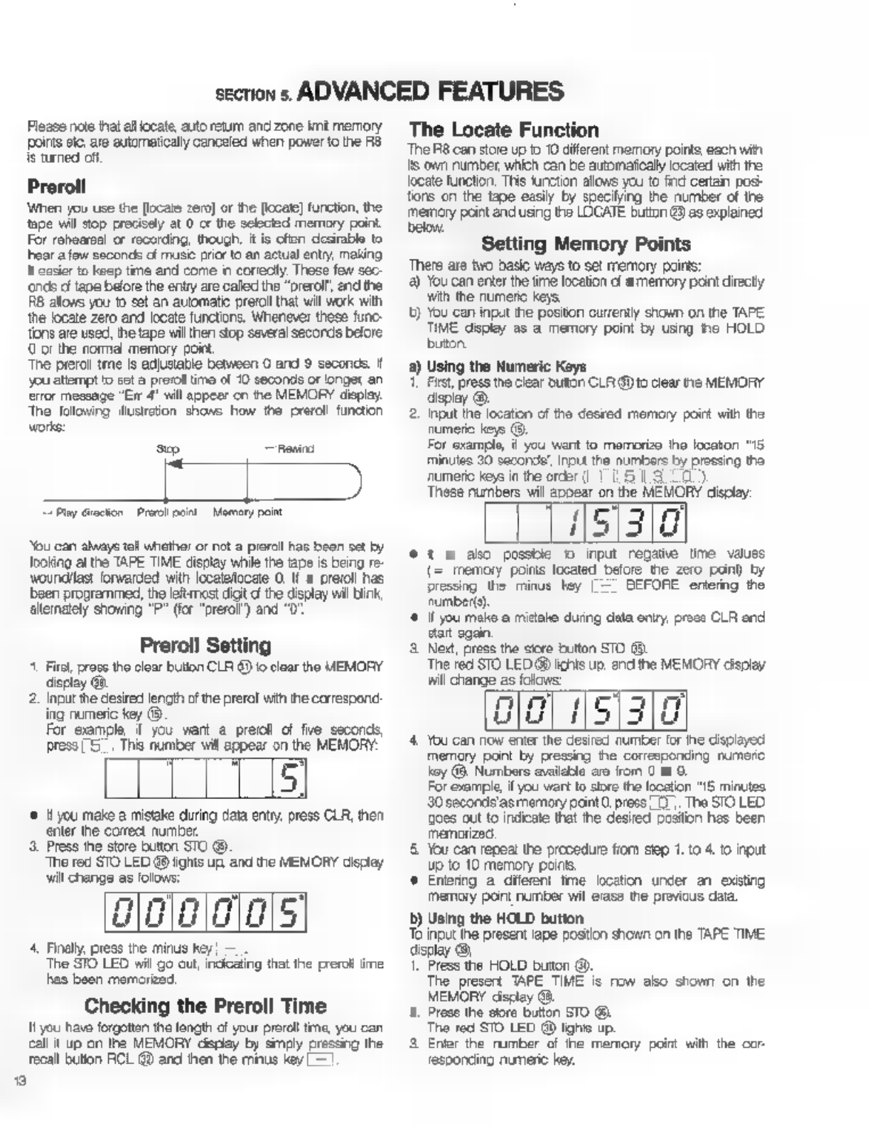
s
section
s.
ADVANCED
FEATURES
Please
пое
that
all
locate,
auto
return
and
zone
imè
memory
points
etc.
аге
automatically
canceled
when
power
to
the
RB
ie
turned
off
Preroll
When
yov
use
the
[locate
zero]
or
the
[locate]
function,
the
tape
wil
stop
precisely
at
0
cr
the
selected
memory
point.
For
rehearsal
or
recording,
though,
it
is
often
desirable
to
ear
a
few
seconds
of
music
prior
to
an
actual
entry,
making
it
easier
to
keep
time
and
come
in
correctly
These
few
sec-
ends
o
tape
before
the
entry
are
called
the
“orerol!,
end
the
R8
allows
you
to
set
an
automatic
preroll
that
will
work
with
the
locate
zero
and
locate
functions.
Whenever
these
func-
tions
are
used,
the
tape
will
then
stop
several
seconds
belore.
C
or
the
norma
memory
point,
‘The
preroll
tme
is
adjustable
between
0
and
9
seconds.
f
you
attempt
to
set
a
preroll
time
of
10
seconds
or
longer
an
error
message
"Err
4"
will
appear
cn
the
MEMORY
display.
Тре
following
illustration
shows
how
the
preroll
function
works:
sp
пены
Lipi
“Play
Grection
Pre
pon
Memory
paint
You
can
always
tall
whether
or
not
а
preroll
has
been
set
by
Joking
at
the
TAPE TIME
display
while
the
tape
is
being
re-
woundllas:
forwarded
with
localelocete
O.
If
а
preroll
has
been
programmed,
the
lett
most
digit
d
the
display
wil
Бик,
alternately
showing
"P"
(for
“prerol’)
and
"0"
Preroll
Setting
^.
First,
press
the
clear
bution
CLR
6)
io
clear
the
MEMORY
display
@.
2,
Input
the
desired
lencth
of
the
prerol
with
the
correspond:
ing
numeric
key
(9.
For
example
f
you
want
а
preroll
of
fie
seconds,
press
5.
Ths
number
will
appear
on
the
MEMORY:
m
rn
Lu
•
уси
make
a
mistake
during
data
entry,
press
CLR,
then
Press
the
store
button
STO
89
The
red
STO
LED
48
lights
up
and
the
MEMORY
display
ninm
гт)
Lu
a
wu
The
STO
LED
will
go
out,
incicaling
that
the
preroll
ime
has
been
memorized.
It
you
have
forgotten
the
length
of
your
preroll
tme,
you
can
call
it
up
on
the
MEMORY
дврјау
by
simply
pressing
the
enter
the
correct
number
wil
change
as
folovs:
4,
Finally,
press
the
minus
key
—
Checking
the
Preroll
Time
recall
button
RCL
@
and
then
the
minus
key
—
The
Locate
Function
The
R8
can
store
up
to
10
different
memory
points,
each
wit
15
own
number,
which
can
be
automatically
located
with
the
locate
function,
This
function
allows
уси
to
find
certain
posi-
tions
on
the
tape
easily
by
specifying
the
number
of
the
memory
point
and
using
the
LOCATE
button
43)
as
explained
below,
б
?
Setting
Memory
Points
There
are
two
basic
ways
to
set
memory
points:
а)
You
can
enter
the
time
location
d
a
memory
point
directy
wth
the
numeric
keys.
t)
You
can
input
the
positon
currently
shown
on
the
TAPE
TIME
display
as
а
memory
point
by
using
he
HOLD
button
2)
Using
the
Numeric
Keys
First,
press
the
clear
button
CLR
@
to
clear
пе
MEMORY
display
©.
2.
при
the
location
of
the
desred
memory
point
with
the
numeric
keys
©.
For
example,
ii
you
want
to
memorize
the
locaton
“16.
minutes
30
second’,
input
the
numbers
Бу
prossing
the
numeric
keys
in
the
order
(1
15130)
These
numbers
will
appear
on
the
MEMORY
display:
151310
*
1
&
ako
possble
о
input
regatie
time
values
memory
poins
located
before
the
zero
pono
by
pressing
the
minus
hey
|
=
BEFORE
entering
the
number(s).
(f
you
mako
a
mistake
during
data
опту,
prose
CLR
and
start
gain.
3.
New,
press
the
store
button
STO
(8.
The
red
STO
LED
@
lichts
up.
and
the
MEMORY
display
will
change
аз
folows:
nm
d
5
3
rr
LIU
i
Ш
4.
You
can
now
enter
the
desired
number
for
ihe
displayed
memory
pont
by
pressing
the
corresponding
numcro
хоу
(&.
Numbers
availeble
are
from
C
to
9.
For
example,
if
you
wart
to
store
the
location
"15
minutes
30
secorde'as
memory
paint
O,
press
07.
The
STO
LED
oes
out
to
indicate
that
ће
desired
position
has
been
memorized
5.
You
can
repeat
the
procedure
fiom
step
1.
to
4.
to
при
up
to
10
memory
ропе,
ө
Entering
a
diferent
tme
location
under
an
existing
memory
pont
number
wil
erase
the
previous
data.
5)
Using
the
HOLD
button.
То
input
the
present
аре
postion
shown
on
the
TAPE
TIME
display
08.
1.
Press
the
HOLD
button
0).
The
present
TAPE
TIME
is
пом
abo
shown
on
the
MEMORY
display
Gà.
2.
Press
the
store
button
STO
(8.
The
red
STO
LED
@
ighis
up.
3
Enler
the
rumber
of
ће
memory
point
with
the
cor-
responding
numeric
key.

Checking
Memory
Points
You
can
easly
check
ary
currenily
stored
memory
point
lo-
cation.
To
do
so,
simply
press
the
recall
bution
RCL
&2,
then
input
the
number
of
the
point
you
want
to
check
with
the
cor
responding
numeric
кој
The
location
time
cf
the
desired
memory
point
wil
appear
on
the
MEMORY
display,
and
the
LOCATE
LED
(D
starts
to
blink.
(f
you
do
not
want
to
use
the
locate
function,
press
CLR
©
to
turn
off
ths
LED)
Clearing
Memory
Points
Individual
memory
років
are
automatically
cleared
when
you
input
a
new
location
time
‘You
can
also
erase
memory
peints
by
pressing
CLR
€),
then
‘STO
@
end
finally
entering
the
number
of
ће
point
to
be
cleared
T
clear
all
curently
stored
memory
points
at
once,
Fold
gown
tne
numeric
keys
O
and
9
and
simultaneously
pressthe.
CLR
button
9).
All
memory
pois
are
also
automatically
cleared
when
the
power
to
the
RB
е
turned
of.
Using
LOCATE
Once
a
memory
point
l'as
been
set,
you
can
have
пе
RE
automaticaly
locate
it
by
caling
t
up
on
the
MEMORY
cis:
play
and
using
the
LOCATE
button
4.
Prase
the
recall
bution
RCL
@.
ts
LED
@
wil
ight.
2.
Inpul
the
number
of
the
desired
memory
point
wth
the
corresponding
numeric
кеу
The
red
RCL LED
goes
out,
and
the
green
LOCATE
LED.
®
begnsio
flash
instead.
The
time
postion
of
the
select-
ед
memory
point
is
shown
on
the
MEMORY
display.
3
To
automatically
fast
forward/rewind
the
tape
to
the
select-
еа
memory
point,
press
пе
LOCATE
buton
@
as
long
as
is
LED
is
fleshing.
This
cen
be
done
in
any
transport
mode—stop,
play,
re-
vind,
oto.
The
LOCATE
LED
remains
lit
during
the
search
proce-
dire
As
soon
2s
tha
одасы
memory
peint
is
reached
the
tape
will
stop
automatically.
The
LOCATE
LED
goes
out.
Instead
of
having
the
tape
stop
at
the
memory
point,
you
сап
also
cause
the
RB
to
automaticaly
start
playoack
when
the
selected
point
is
reached
by
using
the
AUTO
PLAY
funcion
{see
below)
ог
by
pressing
the
PLAY
bution
while
the
tape
is
being
rewound
cr
fast
forwarded.
(The
PLAY
LED
wil
sart
to
bind,
NOTE:
The
locate
function
will
not
atweys
stop
the
tape
procisely
at
the
memory
point-occasionelly,
there
may
Бе
а
difference
up
to
one
second.
This
dovaton
iè
not
a
mallunction.
AUTO
PLAY
1
you
always
went
playback
to
start
automatically
when
using
the
locate
functon,
press
the
AUTO
PLAY
bution
©
to
ight
it
green
LED
@
As
bong
ao
thie
LED
is
Ii,
the
RB
wil
enter
PLAY
mode
whenever
а
memory
point
is
located.
То
cancel
AUTO
PLAN,
simply
press
this
button again,
noing
hat
its
LED
goes
out
AUTO
PLAY
can
aso
be
used
in
combination
with
LOCATE
0
and
AUTO
RETURN.
The
Auto
Return
Function
This
function
allows
you
to
let
the
RB
automatically
rewind
to
any
desired
point—the
"start
point”—as
soon
as
it
reaches
а
certain
other
definable
location
on
the
tepe
called
the
“end
point"
Tho
start
point
and
end
point
of
the
auto
return
zone
can
be
chosen
from
emong
any
of
the
currently
stored
momory
points.
Thus.
at
least
two
memory
locations,
namely
а
start
point
and
an
end
point,
must
be
stored
іп
crder
tn
be
able
То
use
the
auto
return
function.
(See
“Setting
Memory
Points"
above
on
how
to
enter
such
memory
paints)
The
ашо
return
function
can
also
be
used
in
combination
with
auto
play.
The
R8
wil
then
automatically
start
io
play
fter
rewinding
to
the
stan
point,
repeasng
this
operation
‘continuously
until
you
stop
it
Setting
the
Auto
Return
Points
1.
Press
CLR
©
to
clear
the
MEMORY
display.
2.
Enter
the
number
of
the
stert
point,
olowed
by
a
hyphen
(the
minus
key)
and
than
the
number
cf
the
end
point.
(1
is
also
possible
to
input
these
points
in
the
reverse
order,
entering
the
end
point
frst)
For
example,
say
you
have
programmed
fve
memory
points
and
vant
the
R8
to
autornatcaly
rewind
to
point
umber
1
(your
start
point,
eg.
at
the
10
second
location)
a5
soon
as
it
reaches
your
end
pont
number
5
al
1
minute
30
seconds:
Ж
Press
the
numeric
keys
11—175
display
wil
show.
f
CONES
3
Next,
press
the
store
buton
STO
@
The
STO
LED
nil
light,
and
the
MEMORY
display
wil
change
to
show
the
memory
port
wih
the
larger
time
value
trst
(n
our
case
point
5)
а
To
store
these
auto
return
points
in
tne
memory,
press
the
AUTO
АТМ
tution
(8,
The
STO
LED
vill
go
out,
indicating
completion
of
the
auto
return
point
setting.
NOTE:
И
you
made
a
mistake
and
spectied
the
same
‘memory
point
number
as
both
te
start
and
the
end
point
(er
f
the
specifed
memory
port
rumbers
contain
ће
‘same
time
deta),
the
AUTO
АТМ
LED
@
will
start
to
blink,
indicating
an
error
Auto
retum
medo
cannot
then
bo
entered.
When
this
happens,
сопес
the
start/end
point
settings:
Using
AUTO
RTN
Once
the
wo
auto
return
points
have
been
sel,
you
can
enter
auto
return
mode
by
pressing
the
AUTO
RTN
button
(9,
thus
lighing
the
green
AUTO
RIN
LED
29,
As
long
eS
fnis
LED
is
It,
те
R8
vll
automaticaly
rewind
to
the
start
poirt
а
the
auto
return
zone
whenever
Ine
end
poirt
is
reached
during
playback.
While
the
tape
is
beng
Tewourd,
the
LOCATE
LED
@
will
ight.
You
can
combine
auto
return
with
tho
auto
play
function
to
automatically
start
playback
at
the
star.
point.
Simply
press.
AUTO
PLAY
@
so
that
both
the
AUTO
RTN
LED
@
and
the
AUTO
PLAY
LED
(8
are
li.
The
ВВ
will
now
continuously
м
The
MEMORY
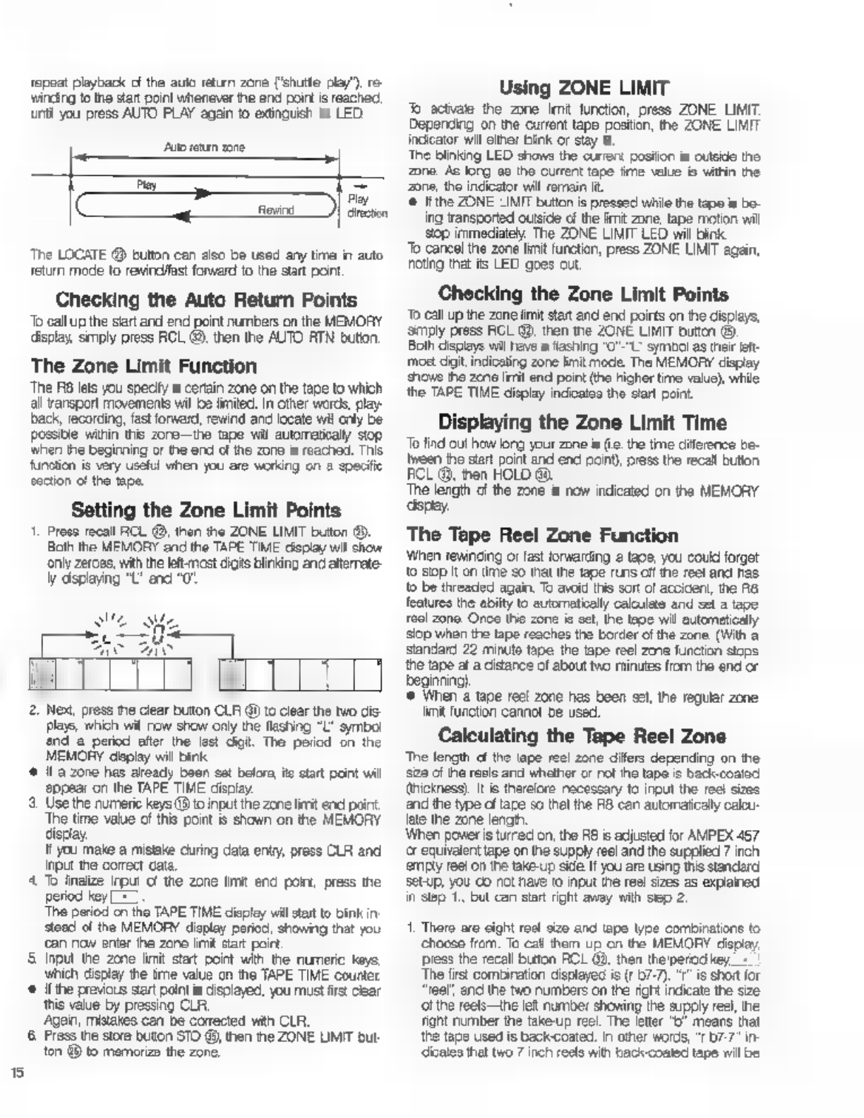
5
repeat
playback
of
the
auto
return
zone
('shutte
play")
re-
winding
to
the
зап
point
whenever
the
end
poirt
is
reached,
unti
you
press
AUTO
PLAY
again
to
extinguish
its
LED.
Ato
return
zone
[X
ко
The
LOCATE
@
button
can
also
be
used
any
ште
in
auto
return
mode
to
rewindfast
forward
to
the
start
point
Checking
the
Auto
Return
Points
То
call
up
the
siart
and
end
point
numbers
on
the
MEMORY
display,
smply
press
RCL
49,
then
the
AUTO
RTN
bution,
The
Zone
Limit
Function
The
RB
lets
you
specify
a
certain
zone
on
the
tepe
to
which
all
ransport
movements
wil
be
limited.
In
other
words,
play-
back,
recording,
fast
forward,
rewind
and
locate
wil
only
be
Possible
within
this
zore—the
tape
wil
ашотакају
stop
when
the
beginning
or
the
end
of
the
zone
is
reached.
This
function
is
very
useful
when
you
are
working
on
a
specific
section
c!
the
tape.
Setting
the
Zone
Limit
Points
1.
Press
recall
RCL
®,
then
the
ZONE
LIMIT
button
®.
Both
the
MEMORY
and
the
TAPE
TIME
display
wil
show
only
zeroes,
with
the
let:
most
digits
blinking
and
alterate-
ly
displaying
“L’
and
“0
Play
direction
s
W
SUL
Me
Lc
rU
AC
LM
2.
Next,
press
пе
clear
button
CLR
@
to
clear
the
two
dis-
plays,
which
wil
пом
show
only
the
flashing
"L'
symbol
nd
а
period
after
the
last
digit.
The
period
on
the
MEMORY
deplay
will
bink
є
Н
а
zone
has
aready
been
sat
befor,
ќе
start
paint
wil
appear
on
the
ТАРЕ
TIME
display.
5.
Use
the
numeric
keys
(8 to
input
the
zone
lirit
end
point
The
time
value
of
this
point
is
shown
on
the
MEMORY
display.
It
you
make
a
mistake
during
data
entry
press
CLR
and
input
the
correct
cata.
4
T
finalize
input
of
the
zone
limit
end
point,
press
the
period
key
[=]
The
period
cn
the
TAPE TIME
displey
will
start
to
bink
in
stead
of
the
MEMORY
display
period,
showing
that
you
сап
now
enter
ће
zane
lint
start
poirt.
5
Input
the
zone
limit
stat
point
with
the
numeric
keys
which
display
the
ime
value
cn
the
TAPE
TIME
counter
*
lí
the
previous
вап
point
is
displayed,
you
must
first
clear
this
value
by
pressing
CLR.
Agan,
mistakes
can
be
conected
with
CLA.
6
Press
the
store
buton
STO
@,
then
the
ZONE
UMIT
but
ton
49
to
memorize
the
zone.
Using
ZONE
LIMIT
Jb
activate
the
zone
Imit
function,
press
ZONE
LIMIT.
Depending
on
the
current
tape
postion,
the
ZONE
LIMIT
indicator
wil
either
bink
or
stay
lt
The
blinking
LED
shows
the
current
posiion
is
outside
the
zone
Ac
long
ae
the
current
tape
‘ime
value
is
within
the
Zone,
the
indicator
will
remain
it.
©
ifthe
ZONE
LIMIT
bution
is
pressed
while
the
tape
is
bo-
ing
transported
outside
of
the
imit
zone,
tape
motion
wil
зор
immediately.
The
ZONE
LIMIT
LED
will
bink
То
cancel
the
zone
limit
function,
press
ZONE
LIMIT
again,
noting
that
its
LED
goes
out.
Checking
the
Zone
Limit
Points
То
call
up
the
zone
limit
start
and
end
poirts
on
the
displays,
Simply
press
RCL
@,
then
the
ZONE
LIMIT
button
(9.
Both
displays
wil
have
a
flashing
"O"-"L-
symbol
as
their
left-
moet
dat,
indicating
zone
limit
mode.
The
MEMORY
display
shows
the
zene
limit
end
point
(the
higher
time
value),
while
the
TAPE TIME
display
indicates
the
start
point.
Displaying
the
Zone
Limit
Time
То
find
out
how
larg
your
zone
is
(е.
the
time
diference
be-
tween
the
start
point
and
end
point),
press
the
recall
bution
FCL
@,
then
HOLD
Go.
The
length
cf
the
zone
5
now
indicated
оп
the
MEMORY
‘spay.
The
Tape
Reel
Zone
Function
Winen
rewinding
or
fast
forwarding
г
taoe,
you
could
forget
to
зор
it
on
time
so
that
the
tape
runs
off
те
reel
and
ras
to
be
threaded
again,
To
avoid
this
sort
of
accident,
the
R8
features
the
abilty
to
automatically
calculate
and
set
a
tape
тесі
zone.
Once
this
zone
ia
oct,
the
tae
wil
automatically
stop
when
the
tape
reaches
the
border
of
the
zone.
(With
a
standard
22
minute
tape
the
tape
reel
zme
function
stops
the
tape
at
a
distance
of
about
two
minutes
from
the
end
or
beginning)
5
When
a
tape
reel
zone
has
been
sel,
the
regular
zone
limit
function
cannot
be
used.
Calculating
the
Tape
Reel
Zone
The
length
cf
the
tape
reel
zone
днев
depending
on
he
зае
of
the
reale
and
whether
or
not
ihe
tape
is
back-coated
thickness).
И
is
therelore
necessary
to
input
the
reel
sizes
and
the
type
of
tare
so
thal
the
RB
can
automaticaly
calou-
(ае
the
zone
length.
When
power
is
turned
on,
the
А8
is
adjusted
for
AMPEX
457
ог
equivalent
tape
on
the
supply
reel
and
the
supplied
7
inch
emply
ree!
on
the
take-up
side
И
you
are
using
this
standard
setup,
уби
co
not
have
to
input
the
reel
sizes
as
explained
in
Step
1.
but
can
start
right
away
with
slep
2.
1.
There
aro
cight
roel
size
and
tape
type
combinations
to
choose
from.
To
са!
them
up
on
the
MEMORY
Черау,
press
the
recall
button
ACL
09,
then
the'perod
key,
The
first
combination
displayed
is
(r
57-7).
"г"
is
short
for
reel",
anc
the
two
numbers
on
the
right
indicate
the
size
‘ol
the
reels—the
left
number
showing
the
supply
reel,
the
Tight
number
the
take-up
reel.
The
letter
"D
means
that
the
tape
used
is
backcoated.
In
other
words,
"r
07-7"
in-
diceles
that
two
7
inch
reels
with
back-coated
tape
will
be
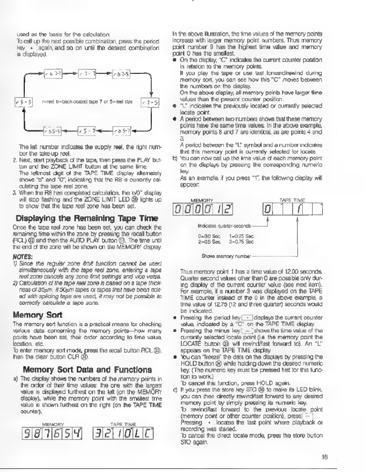
used
as
the
bass
for
the
calculation:
To
call
up
the
next
possible
combination,
press
the
period
key!
«
‘again,
and
so
on
until
the
desred
combination
is
displayed.
FE
eec
[3:3]
rot
tonnage
torte
[27-3]
ој
јан
ој
The
let
number
indicates
the
supply
reel,
the
right
num-
er
the
take-up
real.
2.
Next,
Sart
playback
of
the
tape,
then
press
the
PLAY
but
ton
and
the
ZONE
LIMIT
bution
at
the
same
time
The
leftmost
digit
of
the
TAPE
TIME
display
altenately
shows
"o"
and
"0,
indicating
На!
tho
RE
е
curronty
cal
culating
the
tape
reel
zone,
3.
When
the
R8
has
completed
calculation,
ће
00”
display
will
stop
flashing
and
the
ZONE
LIMIT
LED
@
fights
uo
to
show
that
the
tape
reel
zone
has
been
set
Displaying
the
Remaining
Tape
Time
Once
the
tape
reel
zone
has
been
sel,
you
can
check
the
remaining
time
within
the
zone
by
pressing
the
recall
button
ECU
@
ane
then
the
AUTO
PLAY
outon
P.
The
tme
unti
‘he
end
с
the
zone
ми
be
shown
on
tne
MEMORY
dspay.
NOTES:
1)
Since
the
regular
zone
limit
function
cannot
be
used
‘simultaneously
with
the
tape
reel
zone,
entering
a
tepe
reel zone
cancels
any
zone
fit
setings
and
vice
versa.
2)
Calculation
c
he
tape
reel
zone
f
based
on
з
tape
thick
NESS
Of
qin,
IIaGum
tapes
or
tapes
that
have
been
вої:
ed
with
splicing
tape
are
used,
it
may
not
be
possible
to
corscti
calculate
a
lap
zone.
Memory
Sort
The
memory
sort
function
is
a
practical
means
for
checking
various
cata
concerning
the
memory
polris—how
many
points
have
bean
set,
their
order
secorcing
to
time
value
location,
etc.
To
enter
memory
sort
mode,
press
the
recall
button
RCL
®,
then
the
clear
buon
CLR
G).
Memory
Sort
Data
and
Functions
а)
The
display
shows
the
numbers
of
the
memory
points
in
the
order
of
their
time
values:
the
one
with
the
larges
value
is
cisplayed
furthest
on
the
let
(on
the
MEMORY
display),
while
the
memory
point
with
the
smallest
tme
value
&
shown
furthest
on
the
right
(cn
the
ТАРЕ
TIME
counter).
Mewony
TAPE
TIME
[sias].
(Зет
Пас
Inthe
above
ичтаїоп,
the
sme
values
of
the
memory
points
increase
with
larger
memory
point
numbers.
Thus
memory
poirt
rumber
9
has
the
highest
time
value
and
memory
poirt
0
has
the
smallest
‘©
On
the
displey,
"C"
indicates
the
current
counter
positon
in
relaton
to
the
memory
points
И
you
play
the
tape
or
use
last
ferwardirenind
during
memory
sort,
you
can
see
how
this
"C"
moves
between
the
numbers
on
the
display.
On
the
above
display,
all
memory
points
have
larger
time
values
than
the
present
counter
position
€
71"
indcalos
the
previously
located
or
currently
selected
locate
point.
‘©
А
pericd
between
wo
numbers
shovs
that
these
memory
роїв
have
the
same
time
values
In
the
above
example,
memory
рогі
8
and
7
are
identical,
as
are
points
4
end
А
pericd
between
the
"I"
symbol
and
a
number
indicates
that
this
memory
point
is
currenty
selected
lor
locate
t)
You
can
now
call
up
the
time
value
of
each
memory
point
сп
the
displays
by
pressing
the
corresponding
numeric
tey.
As
an
exemple
if
you
press
eppear:
the
folowing
display
wil
мону
ТАРЕ
TIME
001010
Ца
0
Ра
0-00
Sec
14025
Sac.
2205
508
3-075
Sec
‘Shove
memory
number
—
Thus
memory
point
1
hes
a
time
value
of
12.00
seconds.
Quarter
second
values
oiher
than
O
are
possible
опу
dur-
ing
disolay
cf
the
current
counter
value
(see
next
tem).
For
example,
if
а
number
3
was
displayed
on
the
TAPE
TIME
counter
insteac
of
the
0
in
the
above
example,
а
lime
value
of
12.75
(12
and
three
quarter)
seconds
would
be
indicated
є
Pressing
ће
period
hey!
=
|cisplays
the
current
counter
salua,
indicated
by
а
"С"
on
ho
TAPE
TIME
дорау
*
Pressing
the
minus
key
—
|chows
the
time
value
of
the
currenty
selected
locate
paint
(е.
the
memory
pont
the
LOCATE
buton
GB
wil
rewindifast
forward
tc).
An
"L"
appears
on
пе
TAPE
TME
дорау
©
“bu
can
"freeze!
tne
data
on
the
displays
by
pressing
пе
HOLD
button
@
while
holding
down
the
везе
numeric
tey.
(The
numeric
key
mus:
be
pressed
fist
for
this
func-
ton
to
work)
"b
cancel
ths
function,
press
HOLD
again.
9
H you
press
the
store
key
STO
68
to
make
its
LED
blink,
you
con
then
cirectly
rowind/fast
forward
to
any
desired
Memory
point
by
simply
pressing
its
numeric
ley.
7b
rewindifast
forward
to
the
previous
locate
point
(memory
point
or
other
counter
position),
press!
=
Pressing|
+
|locares
the
last
point
where
playback
or
recording
was
started.
Т
cancel
tns
direct
locate
mode,
press
the
store
button.
STO
адап
16
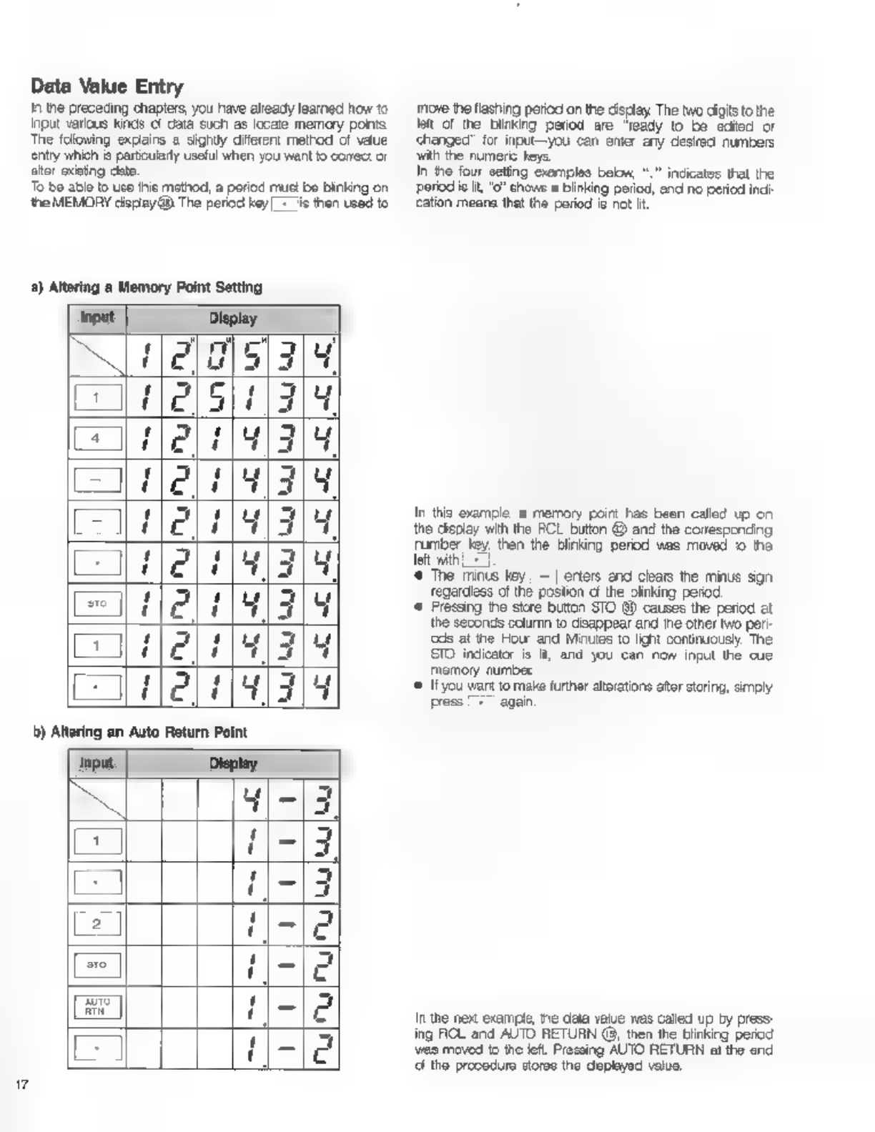
Data
Value
Entry
Tn
the
preceding
chapters,
you
have
already
learned
how
to
input
various
kinds
сї
dala
such
as
locare
memory
ponts
The
folowing
explains
a
sighily
diferent
method
of
value
entry
which
is
particularly
useful
when
you
want
to
cores:
or
aktor
exeting
data
To
be
ablo
to
uso
thie
mothod,
a
poriod
must
bo
blinking
on
the
MEMORY
дврау
0
The
period
кеу.
is
then
used
to
a)
Altering
а
Memory
Point
Setting
input
Display.
(005/34
сл
lels]
1211191319
=
2191319
feli
Hlal
ја
19/3
ЕНЕС
"421793
Lune
(41314
m
Display.
4|-|3
=
1-13
z
1-13
2
11-102
e
се
ABE
Е
a
move
the
flashing
perioc
on
the
cisclay
The
two
digits
to
the
lat
of
the
купка
period
are
"ready
to
be
edited
or
changed’
for
input—you
can
enter
any
desired
numbers
ЗАР
the
numeric
keys.
In
the
four
seting
examples
beon,
“.
indicates
that
the
period
ie
it,
"о?
chows
a
blinking
period,
and
no
period
inci
cation
means
that
the
period
is
not
Н.
In
this
example
a
memory
point
Fas
been
called
up
on
the
display
with
the
FCL
button
@
and
the
correspending
ruber
Key
then
the
Blinking
perod
was
moved
1o
the
left
with
Ls
*
The
minus
key
|
=]
erters
end
clars
the
minus
sign
regardless
of
the
postion
cf
the
linking
регод
*
Fressing
the
store
button
STO
99
causes
the
period
at
the
seconds
column
to
disappear
and
tne
other
two
peri-
cds
at
the
Hour
and
Minutes
to
lignt
continuously.
The
STO
indicator
is
It,
and
you
can
now
input
the
cue
memory
number
«©
Ifyou
want
to
make
further
atorations
ator
storing,
simply
press
|
+
again
In
the
nex
example,
пе
data
value
was
called
up
by
press-
ing
ROL
and
AUTO
RETURN
(8,
then
the
blinking
period
vao
moved
to
the
left.
Pressing
AUTO
RETURN
al
the
end
d
tho
procedura
storas
the
оруса
value,

с)
Entering
a
New
Memory
or
Auto
Return
Point
Error
Messages
The
RB
is
programmed
о
display
certain
"eror
massages’
оп
the
TAPE TIME
counter
to
show
you
when
tne
transport
is
operative
(‘shutoff
error)
and
fo
wam
you
of
mistaken
operation
during
data
memorizaton
(“оте
mode
errors)
A)
Shut-Off
Error.
Wher
the
tension
arm
guides
have
dropped
to
their
lowest
positon,
thus
shutting
of
the
tape
transpor,
the
‘allowing
er-
тог
message
Селог
t")
appears
on
the
TAPE
TIME
Черау
Te
qu
Elrir
Е
Те
be
ableto
use
the
tape
transport
again,
remove
tape
slack
by
rotating
either
or
both
reels
by
hand.
В)
Store
Mode
Errors
Al
o!
these
error
messages
show
that
you
cannot
store
the
current
input
dala.
Check
the
data
and
repeat
entiy
to
cor
fect
t
e
El
f
Indicates
that
the
input
cala
is
not
suitable
as
an
auto
return
point
and
therefore
cannot
ое
stored,
Error
1)
Input
Display
Input
Display
E
R
Т
1
Lj
(|?
Pa
ПР
E
ШЕ
[
ПРЧЕ
-iig
[=]
ПРЕ
5
-|[qses5
|
=le
eg)
tae
5
:
Opa
ae
5
l
WE
OTE
gels
REETA
UN
further
above.
Eror
2)
9
[Elric
e
‘Appears
when
the
dala
on
Пе
MEMORY
display
you
have
attempted
o
memoize
contains
symbols
other
than
numbers.
Er-
J|
ез
Appears
when
the
data
on
the
TAPE
TIME
counter
you
have
attempted
го
stow
contains
symbolo
other
than
numbers.
@
|Elrir
4
e
lea
Лес
cua
wie
SRE
ee
eee
sce
(Eror
4)
Li
19
section
6.
LIST
OF
FEATURES
FRONT
PANEL
@
Reel
Holders
These
secure
the
reels
on
the
red
штиве
(See
pace
6).
Ф
POWER
switch
Tuns
power
to
the
R8
on
(press)
and
cff
release).
©
PLAY
button
il
the
capstan
is
turning
(both
Tension
Arms
are
up),
pressing
this
button
enters
play
mode.
You
can
also
use
PLAY
to
automatically
start
playback
after
а
boate
procedure
(see
"PLAY
LED"
below)
Besides.
pressing
this
button
together
with
STOP
punches
out
during
а
recording
(see
page
10).
Pressing
this
button
together
Е
FWD
or
REWIND
wil
intial
Fast
Search
mode.
@
PLAY
LED
This
indicator
ights
up
when
play
mode
is
entered
and
goes
ом
when
you
exit this
mode
It
you
press
play
button
during
Locate
mode,
the
LED
biirks
tilt
reachs
to
the
locate
point,
and
enters
into
pley
mode
automatcaly.
(©
STOP
button
Press
this
button
momentarily
to
stop
the
transport
in
the
Standby
Mode.
Hod
t
down
for
longer
than
05
seconds
to
stop
transport
im
the
Release
Mode
(See
page
7
for
‘exolenalions
of
Standby
and
Release
Modes)
STOP
is
also
used
in
combinaton
wih
the
PLAY
bution
Э)
to
punch
cut
during
a
recording.
(бее
page
10)
@
STOP
LED
Lights
constantly
in
the
Standby
Mode
enc
binis
in
ne
Release
Mode.
@
F
FWD
(FAST
FORWARD)
button.
Winds
the
tape
at
high
speed
from
let
о
right
orto
the
take-
up
reel.
Pressing
this
button
win
PLAY
bution
vil
rite
Fast
Search
mode.
Pressing
this
button
while
the
tape
is
beirg
fast
forwarded
lowers
tape
speed.
@
F
FWD
LED.
Lights
up
when
the
F
FWD
button
is
pressed.
(©
REWIND
button
Winds
the
tape
at
high
speed
from
right
to
lei
onto
the
sup-
reel
Feind
ms
puton
vir
PLAY
buton
wil
nte
Rew
Search
mode.
Pressing
this
button
wile
the
tape
is
being
rewound
lowers
the
tape
speed,
(9
REWIND
LED
Lights
up
when
tne
REWIND
bution
is
pressed.
(@
REC
(RECORD)
button
Tris
buton
serves
two
purposes.
First,
it
is
used
to
montor
the
input
signal
of
ће
selecied
charnels)
at
the
RB
output
апа
on
the
peek
level
meter.
(The
INPUT
MON
LED
8
blinks
when
this
сопаноп
exist).
The
other
function
of
the
REC
button
is
о
stat
recording
оп
the
solectes
tracks
[ooo
page
9)
by
pressing
i
together
with
the
PLAY
bution
@.
This
operation
can
be
done
from
вор
mode
or
while
tape
is
ring
during
playback
("punch
in?)
@
REC
LEDs
“Tho
Ва
has
two
record
LEDs
—an
orenga
one
and
a
red
ane.
Tho
orange
REC LED
lights
up
t
indicate
the
"record
ready"
condition.
This
condition
is
entered
when
no
track
has
been
selected
for
recording,
and
the
PLAY
button
(3)
and
the
REC
button
(9)
are
pressed
simultanecusy.
The
red
REC
LED
indicates
the
actual
recording
mode,
wncn
is
entered
when
tracks)
has
(have)
been
selected,
and
the
PLAY
bution
@)
and
the
REC
button
@
are
pressed
at
the
same
time.
The
orange
REC
LED
wil
bink
when
an
optional
foot
switch
(Modol
8051)
hao
boon used
to
entor
rehsareal
modo
(coo
Page
10)
©
PEAK
METER
mode
switch
This
switch allons
you
to
select
between
three
types
o!
peak
meter dsiay
modes
PERM
(permanent),
NORMIRST
(nor
rralliesel)
and
TEMP
(temporary)
PERM:
In
this
permarert
PEAK
HOLD
mode,
the
indicator
Segment
showing
the
highest
реак
of
each
channel
is
hed
continuously
on
the
display
until
an
even
higher
peak
level
is
encountered,
or
unti
you
set the
mode
Switch
to
NORM/PST
to
reset
the
display
NORMIRST:
When
set
to
this
postion,
the
display
functions.
asa
поте!
peak
level
meter
This
postion
also
resets
the
PERM
mode
peak
hold
function.
TEMP:
In
this
1
second
PEAK
HOLD
mode,
the
levels
ој
the
highast
peaks
are
held
for
about
one
second
on
the
display.
To
select
the
desired
display
mode,
simple
move
this
switch
to
the
corresponding
position.
(9
SAFE/RDY
(READY)
LEDs
When
these
record
track
indicators
are
green,
the
cor-
responding
tracks
are
“sale’—ie
no
recording
is
possible
Vihen
these
LEDs
alternately
blin
red
and
green,
they
ind
cate
which
tracks
are
"ready"
for
recording
Mhile
tracks
are
actually
being
recorded,
the
correspond
ing
SAFEIRDY
пасат
are
constantly
it
red
®
Numeric
key
раа
This
key
pad
incucesten
number
keys
from
0
to
9,
a
period
key
and
а
minus
key
(hyphen).
They
are
used
for
data
input
ard
various
command
eortrds.
@
PITCH
control
The
pitch
contio
knob
adjusts
the
tape
speed
over
а
++/—10%
range.
Rotaing
itclackwise
(n
the direction
of
the
^t"
symbol)
increases
ће
speed,
while
rotating
it
in
the
оног
droction
docresses
it
The
center
postion,
where
the
knob
cicle
into
place,
corresponds
to
the
standard
speed
of
88
omis
(15
is)
@
AUTO
PLAY
button
Other manuals for R8
3
Table of contents
Other Fostex Measuring Instrument manuals


