Sherwood Scientific 360 User manual

360 91 001 Issue 2 10th June 2010 ECN 617
G:\DOCUMENT CONTROL\Manuals\Flame\360\36091001 M360 Operator Manual Issue 2.doc
Model 360
Flame Photometer
Operator
Manual
Copyright 2010©Sherwood Scientific Ltd.
All rights reserved.

Model 360 Flame Photometer
360 91 001 Issue 2 10th June 2010 ECN 617 - 2 -
Intended Use
This operator’s manual contains complete instructions for setting up and using the Model 360.
Service information for use by appropriately qualified personnel is also available.
The Model 360 is intended for use by persons knowledgeable in safe laboratory practices. If the
instrument is not used in accordance with these instructions for use, the protection provided by
the equipment may be impaired.
There are no user replaceable parts within the instrument. Do not remove the covers from the
instrument.
Sherwood Scientific Limited and its authorized Distributors consider themselves responsible for
the effects of safety, reliability and performance of the Model 360 only if: -
• Assembly operations, extensions, re-adjustments, modifications or repairs
are only carried out by persons authorized by them.
• The electrical installation of the relevant room complies with IEC
requirements or the local regulatory code.
• The equipment is used in accordance with the instructions for use.
The information contained in this manual was correct at the time of going to print. However,
Sherwood Scientifics policy is one of continuous product improvement and the right to change
specifications, equipment and maintenance procedures at any time, without notice, are reserved.
This manual is copyrighted, and all rights are reserved. No part of this manual may be
reproduced by any means or in any form without prior consent in writing.
Sherwood Scientific Ltd,
1 The Paddocks,
Cherry Hinton Road,
Cambridge,
CB1 8DH,
United Kingdom
Tel +44 1223 243444
Fax +44 1223 243300
Email info@sherwood-scientific.com
www.sherwood-scientific.com

Model 360 Flame Photometer
360 91 001 Issue 2 10th June 2010 ECN 617 - 3 -
Contents Page
Intended Use.................................................................................................................................... 2
1 Introduction ................................................................................................................................. 5
1.1 Introduction............................................................................................................. 5
1.2 Summary of the Test ............................................................................................... 5
1.3 Flame Photometry Principles of Operation ............................................................... 6
1.4 Reagents.................................................................................................................. 6
Dilutions................................................................................................................. 6
Storage................................................................................................................... 6
Purification............................................................................................................. 6
2 Installation................................................................................................................................... 7
2.1 Services Required.................................................................................................... 7
Electrical Supply..................................................................................................... 7
Fuel........................................................................................................................ 7
Air.......................................................................................................................... 7
Waste Container...................................................................................................... 7
2.2 Site Conditions........................................................................................................ 8
2.3 Unpacking............................................................................................................... 8
Accessory List ........................................................................................................ 8
2.4 Assembly ................................................................................................................ 9
2.5 Connecting a Chart Recorder................................................................................. 13
3 Performance Characteristics and Specification............................................................................ 14
3.1 Readout................................................................................................................. 14
3.2 Limits of Detection................................................................................................ 14
3.3 Specificity............................................................................................................. 14
3.4 Accuracy............................................................................................................... 14
Drift ..................................................................................................................... 14
Reproducibility ..................................................................................................... 15
3.5 Warm Up .............................................................................................................. 15
3.6 Sample Requirement.............................................................................................. 15
Type..................................................................................................................... 15
Method of presentation.......................................................................................... 15
Volume................................................................................................................. 15
3.7 Chart Recorder Output .......................................................................................... 16
3.8 Environmental Conditions...................................................................................... 16
Temperature.......................................................................................................... 16
Humidity............................................................................................................... 16
Installation Category............................................................................................. 16
3.9 Power Requirements.............................................................................................. 16
3.10 Size....................................................................................................................... 16
3.11 Weight .................................................................................................................. 16

Model 360 Flame Photometer
360 91 001 Issue 2 10th June 2010 ECN 617 - 4 -
4 Operating Instructions................................................................................................................ 17
4.1 Front Panel Controls and Indicators....................................................................... 17
Power on............................................................................................................... 17
Flame on............................................................................................................... 17
Blank.................................................................................................................... 17
Fine and Coarse .................................................................................................... 17
Na, K, Li, Ca & Ba LED ...................................................................................... 17
Hold ..................................................................................................................... 17
4.2 Rear Panel Controls and Connectors...................................................................... 19
Power ................................................................................................................... 19
Data output........................................................................................................... 19
Gas....................................................................................................................... 19
Air........................................................................................................................ 19
4.3 Initial Adjustment.................................................................................................. 20
4.4 Operating Instructions ........................................................................................... 21
4.5 Shutdown Procedure.............................................................................................. 23
4.6 Operating Hints..................................................................................................... 23
5 Operational Precautions and Limitations..................................................................................... 24
5.1 General ................................................................................................................. 24
5.2 Hazards................................................................................................................. 24
6 Maintenance............................................................................................................................... 25
6.1 General ................................................................................................................. 25
6.2 Daily Maintenance................................................................................................. 25
6.3 Weekly Maintenance.............................................................................................. 25
6.4 Monthly Maintenance............................................................................................ 25
6.5 Six-Monthly Maintenance...................................................................................... 25
6.6 Nebuliser............................................................................................................... 26
Operational Check................................................................................................. 26
Cleaning the Nebuliser .......................................................................................... 26
6.7 Cleaning the Mixing Chamber, Burner and Drain................................................... 27
6.8 Cleaning the Optical Filters and Glass Chimney..................................................... 28
6.9 Deproteinising or Disinfecting Procedure ............................................................... 29
7 Troubleshooting......................................................................................................................... 30
7.1 Power on LED not illuminated............................................................................... 30
7.2 Flame on LED not illuminated............................................................................... 30
General................................................................................................................. 30
Air Supply............................................................................................................ 30
Fuel Supply .......................................................................................................... 30
7.3 Unable to set display to zero .................................................................................. 30
7.4 Unable to set display to standard reading................................................................ 31
7.5 Unstable results..................................................................................................... 31
7.6 Non-linear Results................................................................................................. 31
8 Spares and Accessories .............................................................................................................. 32
8.1 Ordering Information............................................................................................. 32
8.2 Spares and Accessories.......................................................................................... 32
8.3 Standard Solutions................................................................................................. 33
Appendix A Bibliography.......................................................................................................... 34
Appendix B Guidelines on Standards and Samples .................................................................... 34
Product Warranty .................................................................................................................38

Model 360 Flame Photometer
360 91 001 Issue 2 10th June 2010 ECN 617 - 5 -
1 Introduction
1.1 Introduction
The Model 360 is a single channel, low temperature flame photometer. It is supplied as
standard, for the determination of Sodium (Na), Potassium (K), Lithium (Li), Calcium
(Ca) and Barium (Ba), working with either Propane/Butane or Natural Gas fuels.
NOTE The fuel gas for which the gas control pod on your instrument is designed for
use with is indicated by the label on the rear of the left hand side of the instrument.
WARNING It is important that only the fuel gases indicated on the rear of the
instrument are used; using the incorrect fuel may be dangerous, may damage the
instrument and will be detrimental to the performance of the unit.
Please refer to Section 8.2 for a complete list of spares and accessories.
The Model 360 has a fail-safe device, which automatically stops the gas flow if the flame
does not ignite, or if during operation, the flame is extinguished. It also has an air
pressure switch so that if the air pressure falls below a specified value the flame will not
ignite or will be extinguished.
For the purposes of this manual the terms Atomiser and Nebuliser are interchangeable.
1.2 Summary of the Test
NOTE References are listed in Appendix A.
In many applications, rapid availability of results is of prime importance. By flame
photometry both Sodium and Potassium results on a single sample can be available in
less than 5 minutes of the sample reaching the laboratory. (The same is true of Lithium
results, a determination that was never carried out before the advent of flame
photometry). A simple dilution step is all that is required; therefore sample handling,
losses and inaccuracies are at a minimum (Ref. 3-10)
Prior to the advent of flame photometry, Sodium and Potassium were typically
determined gravimetrically after the precipitation of relatively insoluble salts such as
Sodium Uranyl Zinc Acetate (Ref. 1) and Potassium Chloroplatinate (Ref. 2). As with all
chemical methods for these two elements there were cross interferences and also
interference from other ions such as NH4+. Many analytical steps such as protein
precipitation or ashing of the sample were involved with all the attendant losses and
inaccuracies and the complete procedures required many hours.

Model 360 Flame Photometer
360 91 001 Issue 2 10th June 2010 ECN 617 - 6 -
1.3 Flame Photometry Principles of Operation
When a solution is aspirated into a low temperature flame, in an aerosol, each droplet of
water evaporates leaving a solid core of the residue of evaporation. The core further
breaks down to the molecular level, and provided the molecules are not too refractory,
progress to form atomic species. The atom then is excited by the flame and its electron
temporarily moves to a higher energy state.
When the electrons return to the ground state, they lose the excitation energy and a
discrete wavelength of visible light is emitted, characteristic of the atom. The emitted
light can be isolated from other light wavelengths by an optical filter. The amount of
light being emitted is proportional to the number of atoms in the flame, and it follows,
the concentration of that atom in the original solution. The amount of light emitted can
be measured by a suitable photodetector.
The photodetector generates an electrical signal which is amplified and displayed on a
digital readout.
1.4 Reagents
Sherwood Scientific supplies a wide range of reagents, including standards, diluent and
maintenance solutions, for use with the Model 360 Flame Photometer.
Please refer to Section 8.3 for a complete list of the reagents.
Dilutions
Samples and standards must be diluted with the same batch of diluent, made up of 1 part
Diluent Concentrate to 999 parts deionised or good quality distilled water.
The same batch of diluent should be used to zero the instrument and to prepare dilutions
of standards and samples. This will prevent variations in water purity affecting the
measurements.
Great care should be taken so that contamination does not occur when preparing the
samples and standards. Remember that the accuracy of the instrument is dependent on
the accuracy and purity of the standards used for calibration.
Storage
All solutions should be stored away from direct sunlight, in a cool place (below
+25°C/+77°F), in an airtight container to prevent evaporation and discolouration. Glass
containers should not be used, as they can affect Na concentration levels. Prolonged
exposure to the atmosphere must be avoided to prevent evaporation of standard
solutions, which could affect concentration.
Purification
No purification is required for Sherwood Scientific standard solutions.

Model 360 Flame Photometer
360 91 001 Issue 2 10th June 2010 ECN 617 - 7 -
2 Installation
2.1 Services Required
Electrical Supply
The Model 360 is powered with a universal self adjusting power supply.
CARE should be taken to use the correct adaptor for the local supply.
Fuel
The Model 360 comes in two versions, one for use with Butane or Propane, another for
use with Natural Gas. The use of Natural Gas is not advised for accurate work.
Propane/Butane
A supply of High-grade Propane, Butane or Propane/Butane mixture, free of heavy
hydrocarbon deposits, regulated at the cylinder to 2.1kg/cm² (30psig), flow rate at least
0.4 litres per minute. (Calor gas is perfectly acceptable). The use of industrial quality gas
is not recommended as impurities can enter the delicate gas regulators and can leave
deposits of oil and dirt, which will render the instrument inoperable.
Natural Gas
Natural gas at 3 to 10 inches water gauge.
NOTE Natural Gas may give reproducibility results outside specification.
NB The positioning of Gas cylinders should conform to National and local regulations.
Air
A supply of clean, dry, oil-free air, at minimum 1kg/cm² (14psig), flow rate 6 litres per
minute. Any contamination, moisture or variation in supply pressure will directly affect
the performance of the instrument.
A suitable Sherwood Scientific air compressor is listed in Section 8.2.
Waste Container
A sink or waste container sited to the right of the instrument will ensure the minimum
length of waste tubing. Do not use a waste container with high sides, as this will cause
the drain tube to be lifted above the level of the constant head drain.
WARNING The liquid coming out of the drain will still contain any hazardous materials
that were in the original samples and should be handled and disposed of
with the same care. Waste liquid should always be considered to be of a
pathogenic nature where the instrument is used in a clinical environment

Model 360 Flame Photometer
360 91 001 Issue 2 10th June 2010 ECN 617 - 8 -
2.2 Site Conditions
WARNING Under no circumstances install the instrument beneath overhanging
cupboards. There must be at least 1 metre of clear space above the
chimney.
For optimum performance, this instrument should be installed in
accordance with the following conditions: -
1. The environment must be clean and free from dust.
2. The instrument must be placed on a strong, level worktop, free from vibration. The
Model 360 requires approximately 400mm x 400mm of bench space, which
includes a distance of 100mm between the edge of the bench and the front of the
instrument for solutions and clearance at the rear for fuel and air tubing, with clear
access to the mains supply switch.
3. Avoid sites that expose the instrument to direct sunlight or draughts.
4. To meet specification the ambient temperature must be within the range 10°C to
35°C and the maximum relative humidity not greater than 85%, non-condensing.
2.3 Unpacking
1. Unpack the instrument and accessories.
NOTE The Model 360 weighs 5.6kg, follow safe lifting techniques.
2. Check all items for damage.
3. Check that all the items on the Accessory List have been delivered. Contact your
Sherwood Scientific distributor if you have any problems.
4. The Model 360 is shipped with the following items:
Accessory List
CAT. NO. ITEM QUANTITY
001 72 043 Air tubing, nylon reinforced 2 metres
001 72 114 Fuel tubing 2 metres
400 22 000 Drain tube, (all flame #20411 on) 1 metre
001 53 313 Universal Multi-adapter PSU 12Vdc 1
100 99 010 Nebuliser cleaning wire, pack of 3 1 pack
420 08 102 Nebuliser 1
400 22 003 Nebuliser inlet tube, polythene, 150mm 1
360 91 001 Operators Manual, English 1
001 06 016 Hose clip 11-16mm 4
001 56 620 Flame Photometer Standard, 1000ppm Na 1 x 100ml
001 56 621 Flame Photometer Standard, 1000ppm K 1 x 100ml
001 56 622 Flame Photometer Standard, 1000ppm Li 1 x 100ml
001 56 623 Flame Photometer Standard, 1000ppm Ca 1 x 100ml
001 56 124 Flame Photometer Standard, 1000ppm Ba 1 x 100ml
360 91 000 M360 Assembly Procedure Guideline 1
Model 360 Flame Photometer
360 91 001 Issue 2 10th June 2010 ECN 617 - 9 -
2.4 Assembly
EQUIPMENT REQUIRED: -
Flat blade screwdriver.
You may wish to refer to the M360 Assembly Procedure sheet in addition to the
following:
1. Unpack the instrument and accessories, removing all packaging.
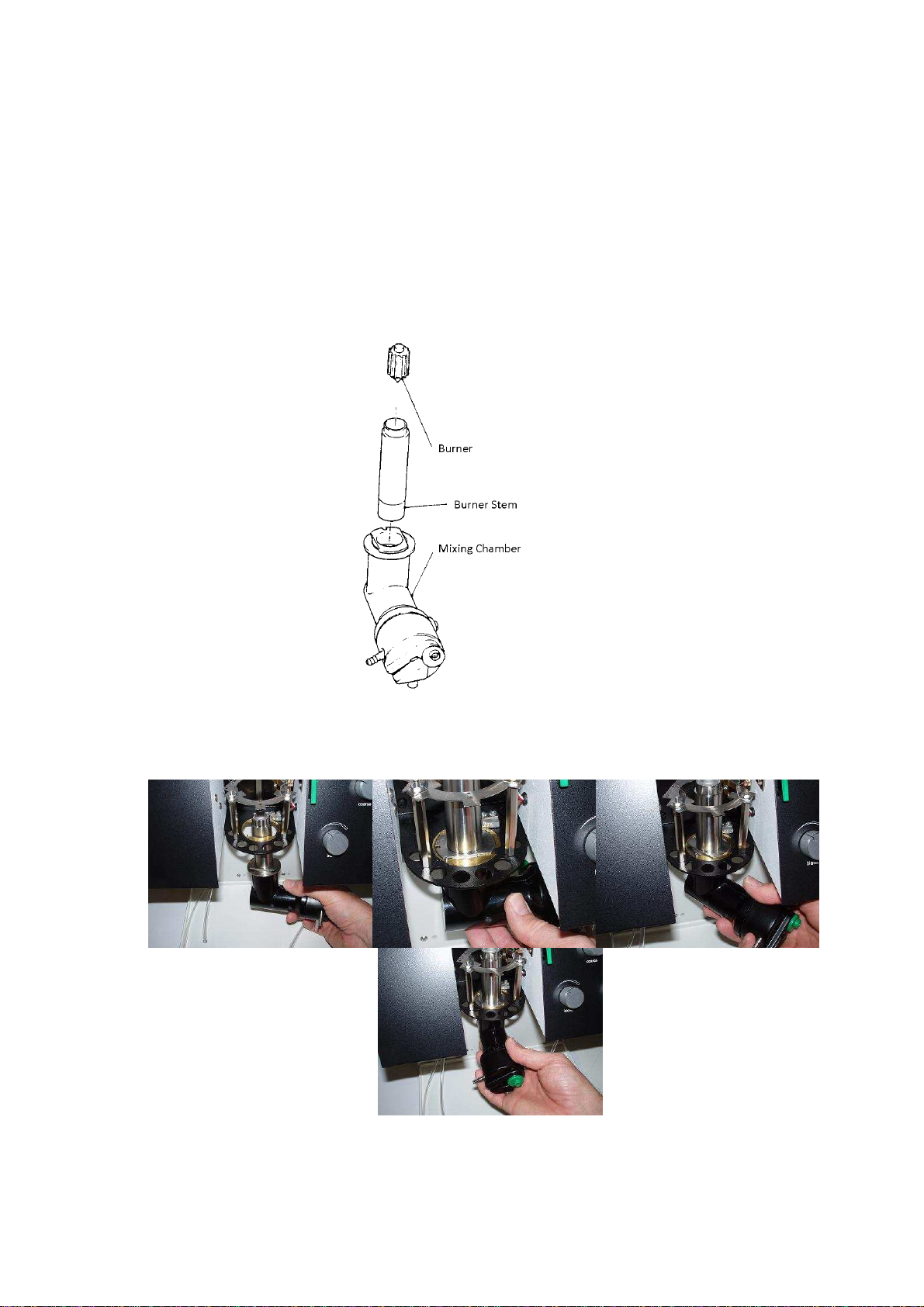
2. Insert the Burner Stem into the Mixing Chamber Assembly and the Burner into
the Burner Stem.
Then fit this into the shaped hole in the chimney tray, turning it 90° clockwise to
lock it in position.
Attach the 6mmOD tube (item 6, Figure 2.4) from the Gas Pod to the side port
of the Mixing Chamber Assembly.
1 2 3
4

Model 360 Flame Photometer
360 91 001 Issue 2 10th June 2010 ECN 617 - 10 -
Installation continued
2.4 Assemblycontinued
3. Slide the Constant Head and Drain over the screws on the right hand side of the
Vanity/Rear Panel. Connect the ‘U’ Tube (item 5, Figure 2.4) to the bottom
outlet of the Mixing Chamber Assembly.
4. Place the Glass Inner Chimney centrally on the Upper Shelf.
Model 360 Flame Photometer
360 91 001 Issue 2 10th June 2010 ECN 617 - 11 -
Installation continued
2.4 Assemblycontinued
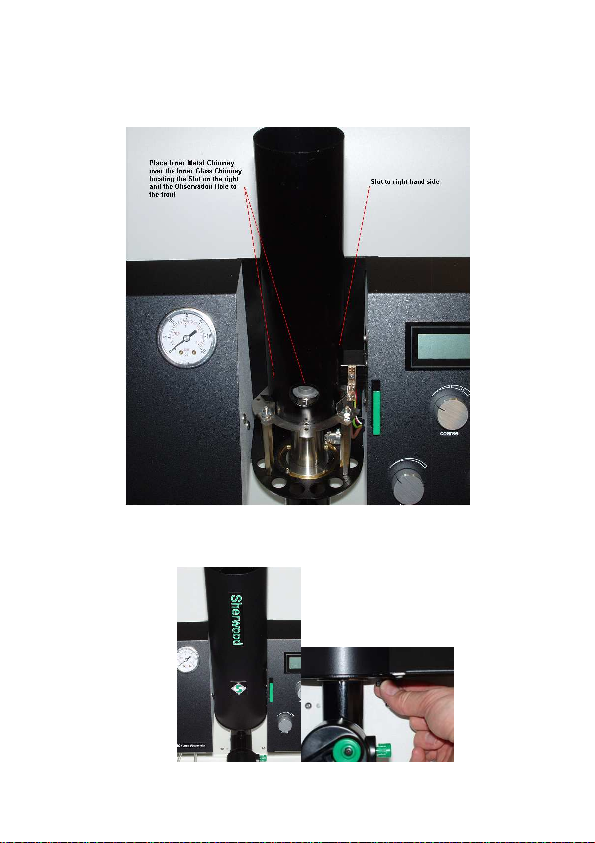
5. Slide the Metal Inner Chimney over the Glass Inner Chimney, locating it within
the three spring clips.
6. Place the Outer chimney around this and secure it to the chimney tray with two
thumbscrews from underneath.
Model 360 Flame Photometer
360 91 001 Issue 2 10th June 2010 ECN 617 - 12 -
Installation continued
2.4 Assemblycontinued
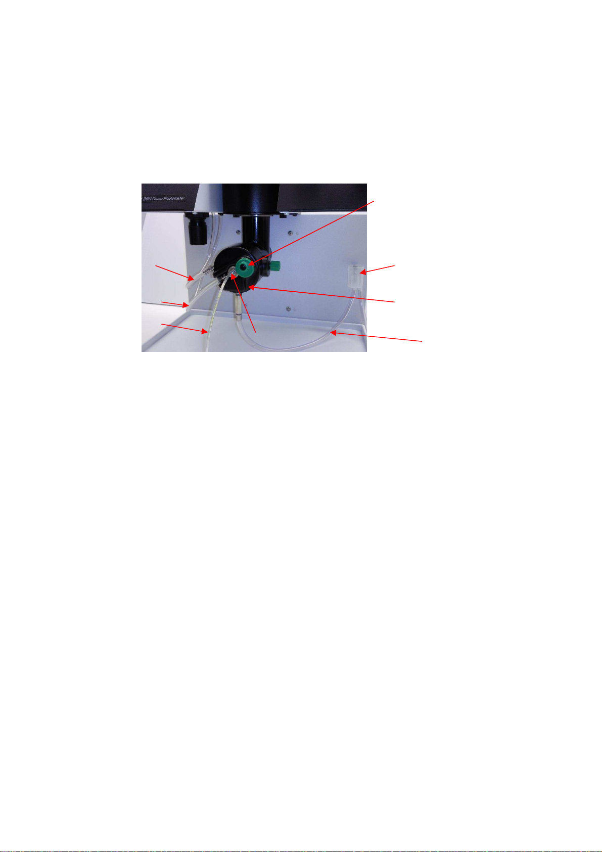
7. Remove the nebuliser from its box and push the nebuliser barb into the air tubing
(item 3, Figure 2.4). Fit the nebuliser, with its flat sealing washer, to the mixing
chamber and position the retainer to lock it into position (item 2, Figure 2.4). Fit
the nebuliser inlet tube (item 7, Figure 2.4), making sure that it is pointing
downwards.
Figure 2.4 Mixing Chamber
1. Nebuliser, 2. Nebuliser retainer. 3. Air tubing. 4. Constant head & drain, 5. ‘U’ tube,
6. Fuel tubing, 7. Inlet tube.
8. Connect the length of rubberised fuel tubing, (001 72 114) supplied, between the
fuel inlet connector (item 3, Figure 4.2) on the rear of the Gas Pod, and the
cylinder regulator outlet connector. Secure with Hose tubing clamps (001 06
016), supplied.
NOTE The connection at the cylinder end of the tube must comply with
National regulations.
9. Turn on the fuel supply and check all connectors for leaks, using soap solution.
Do not use the instrument until you are satisfied that the installation is leakproof.
10. Connect the length of reinforced Nylon hose (001 72 043), supplied, between the
air compressor outlet and the air inlet connector (item 4, Figure 4.2) on the rear
panel. Secure both ends with Hose tubing clamps (001 06 016), supplied.
2
4
3
5
1
3
6
7
Model 360 Flame Photometer
360 91 001 Issue 2 10th June 2010 ECN 617 - 13 -
Installation continued
2.4 Assemblycontinued
11. Fit the length of drain tubing (400 22 000) to the outlet on the Constant Head
and Drain. If necessary shorten the tube or connect a suitable length of tubing
(not supplied), to extend the drain tubing to carry waste to a sink or other drain
receptacle. The downward flow of waste must not be restricted.
12. Make sure that the Constant Head Drain is pushed fully down on its locating
screws. Use a wash bottle to fill the ‘U’ Tube with deionised water. Sufficient
water should be used to purge the tube of air. Allow excess water to flow back
into the drain.
IMPORTANT Do not continue until you are satisfied that the ‘U’ tube has been
completely filled with water, and is purged of air.
13. If necessary, set the power switch (rear of instrument) to the off position.
Connect the Power Supply Unit to the power receptacle on the rear panel and
connect the plug to a convenient supply socket.
14. If a chart recorder is to be used with the instrument continue with Section 2.5. If
not, continue with Section 4, Operating Instructions.
2.5 Connecting a Chart Recorder
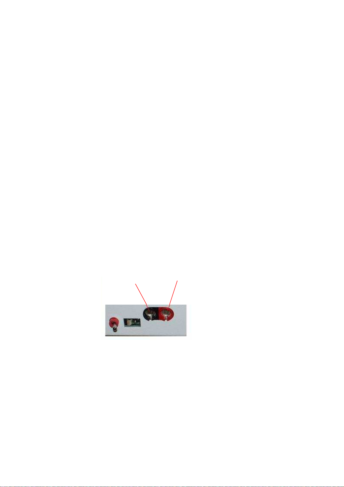
1. Connect the black (-ve) recorder input lead to the black data output socket on
the rear panel of the instrument.
2. Connect the red (+ve) recorder input lead to the red data output socket on the
rear panel of the instrument.
3. If the chart recorder has an input-shorting link fitted, connect it between the
black (negative) input and the earth input. This may reduce interference and
produce a better trace.
4. Continue with Section 4, Operating Instructions.
-ve Black +ve
Red

Model 360 Flame Photometer
360 91 001 Issue 2 10th June 2010 ECN 617 - 14 -
3
Performance Characteristics and Specification
3.1 Readout
3½-digit light emitting diode (LED) display
Display range 0 to 1999.
NOTE If negative values are displayed the instrument is operating outside of the
recommended measurement range.
3.2 Limits of Detection
Na 0.1ppm
K 0.1ppm
Li 0.1ppm
Ca 2.0ppm
Ba 20ppm
These are sample concentrations directly entering the flame photometer after dilution.
3.3 Specificity
Interference from Na, K and Li when equal in concentration to the test element will
be less than 0.5%.
When determining Ca, interference will be seen if Sodium is present in the samples.
You should determine the level of that interference at the concentration being
determined in your samples. When determining Barium you should be aware that
there is potential for a very considerable interference from Potassium if any is
present in the sample. For Potassium determinations there is negligible interference
from Barium.
3.4 Accuracy
Linearity Better than ± 2% when measured at mid-point of a 3ppm solution of Na or K
or Li set to a display of 100.
e.g. 3ppm Na calibrated to 100 on the display will read 48 to 52 at mid-point.
NOTE A minimum 30 minutes warm up aspirating blank solution must be allowed to
meet the drift specification, refer to Section 3.5.
Drift
Better than 2% over 30 minutes when continuously aspirating 3ppm K set to read 300.
With the same sensitivity settings zero drift better than 2% over one hour. (Warm up
time required).

Model 360 Flame Photometer
360 91 001 Issue 2 10th June 2010 ECN 617 - 15 -
Performance Characteristics and Specification continued
Reproducibility
NOTE The following specification is correct for use on Propane or Butane. If Natural
Gas is used the reproducibility may be poorer.
≤1.5% CV (coefficient of variation) for 20 consecutive readings from an
aqueous standard of 10ppm Potassium set to 1000. Readings taken 20 seconds
after introduction and with a Blank aspirated for 10 seconds between each
standard reading.
≤1.0% CV for 20 consecutive readings taken at 20 second intervals without
removing the uptake tube from a 10ppm Potassium solution set to 1000.
NB CV is defined as Sample Standard Deviation x 100
Mean Reading
3.5 Warm Up
To achieve the stated specification the flame must be alight for a minimum of 30
minutes, with diluent being aspirated.
3.6 Sample Requirement
Type
Dependent on application. However, samples should be water-based and not highly
viscous nor non-homogeneous.
Organic solvents affect the air/fuel ratio, could attack the mixing chamber materials and
can affect the safety operation of the Gas Trap (constant head drain) and should be used
with great caution.
Method of presentation
The sample is presented to the nebuliser from a sample cup, test-tube, or other suitable
container.
NOTE Aspiration efficiency can change depending on the vertical distance between the
sample and the nebuliser capillary, the depth of submersion of the sample
uptake tube and shape of the sample vessel. This means that small reading
differences can be noted if samples and standards are moved around
significantly during aspiration. Also differences may occur if sequential samples
are not consistently located or if long term repeatability tests are being
conducted from one vessel and the sample level drops significantly during the
duration of the test. A low form, wide mouthed vessel is preferred.
Volume
The minimum practical diluted sample volume required for 20 seconds aspiration is
2.5ml.

Model 360 Flame Photometer
360 91 001 Issue 2 10th June 2010 ECN 617 - 16 -
Performance Characteristics and Specification continued
3.7 Chart Recorder Output
Nominal 100mV signal output per 1000 display units.
3.8 Environmental Conditions
Temperature
Operating +10°C to +35°C; Transportation -40°C to +45°C
Humidity
Operating 85% maximum at +35°C
Transportation 95% maximum at +45°C (Non-condensing)
The instrument specification will be unaffected by an ambient temperature change of 4°C
(or less) per hour, within the range +10°C to +35°C, with a maximum of 7°C shift
during 8 hours.
Installation Category
Installation Category 1
3.9 Power Requirements
The Model 360 is provided with a Universal Power Supply accepting input voltages
over the range 100-240 V AC, 50/60Hz 0.6A with output to the instrument of 12V DC
1.25A.
3.10 Size
Overall, including chimney and rear panel connectors,
500mm high x 300mm wide x 230mm deep.
(We recommend placement of the unit 100mm back from the front edge of the bench
upon which the instrument is sited).
3.11 Weight
5.6kg, instrument only.

Model 360 Flame Photometer
360 91 001 Issue 2 10th June 2010 ECN 617 - 17 -
4 Operating Instructions
4.1 Controls and Indicators (See Figure 4.1).
Power on
LED which illuminates when the instrument is switched on.
Flame on
LED which is illuminated when the flame is alight. The instrument has a fail-safe system, if
the flame is extinguished the LED will flash and the fuel supply is shut off.
Flame alight & air pressure OK = LED constantly on
Flame out & air pressure OK = LED flashing
Flame out & air pressure low = LED flashing
Blank
This control is used to set the display to zero while aspirating a blank solution.
Fine and Coarse
These two controls are used to set the display to an appropriate concentration reading,
while aspirating a standard solution. The coarse control is a four position rotary switch and
the fine control is a 10-turn potentiometer.
Na, K, Li, Ca & Ba LED
The Filter Stick is pulled out or pushed in to select the filter for the analyte to be determined
and the appropriate LED is illuminated.
Hold
This touch control is depressed to retain the reading displayed and is indicated by the
illuminated LED.

Model 360 Flame Photometer
360 91 001 Issue 2 10th June 2010 ECN 617 - 18 -
Operating Instructions continued
4.1 Controls and Indicators continued
Figure 4.1 Controls

Model 360 Flame Photometer
360 91 001 Issue 2 10th June 2010 ECN 617 - 19 -
Operating Instructions continued
4.2 Rear Controls and Connectors
Power
The switch (item 1, Figure 4.2) turns the power supply on and off. When the instrument is
switched on (1), the power on LED is illuminated, and an ignition cycle is initiated. When
switched off (0), the flame is extinguished, the fuel supply is shut off and the power supply
to the instrument is switched off.
Data output
Two colour coded chart recorder sockets (item 2, Figure 4.2). The range is 0V to
+200mV, the output signal is on the red socket with respect to the black socket.
Gas
Ø7mm fuel inlet connector (item 3, Figure 4.2). For attaching the fuel gas tubing to the
instrument from the cylinder regulator outlet; Refer to Section 2.1 for details of fuel
type, pressure and flow rate.
Air
Ø7mm connector (item 4, Figure 4.2). For attaching the air inlet tubing to the instrument
from the air compressor outlet; See Section 2.1 for pressure and flow rate specifications.
Figure 4.2 Rear Panel
2
1
3
4

Model 360 Flame Photometer
360 91 001 Issue 2 10th June 2010 ECN 617 - 20 -
Operating Instructions continued
4.3 Initial Adjustment
NOTE The following instructions assume that the air compressor is switched on and
supplying the instrument with air.
1. Check that the air pressure gauge (on the left panel) indicates a reading between
11 and 13psig. If it does not, lower the air regulator locking ring and adjust the
regulator for a reading of 11 psig on the air pressure gauge. Raise the locking
ring to lock the air regulator adjuster.
WARNING The air compressor should always be switched on before the flame
is ignited. The gas will not flow without sufficient air pressure
2. Check the Gas Trap ‘U’ tube is filled with water; (ref. Section 2.4, paragraph
12).
WARNING Always check that the gas installation is leak-proof before initiating
an ignition cycle.
5. Turn on the fuel supply at source.
6. Operate the power switch on the instrument rear. The power on LED will
illuminate, and an ignition cycle will commence.
7. If the flame on LED has not illuminated before the end of the ignition cycle,
switch off and wait ten seconds. Then switch on again to initiate another ignition
cycle.
8. If the flame on LED does not flash during the ignition cycle, check that the air
pressure is 11psi.
9. Repeat this cycle twice to allow sufficient time for the fuel to reach the burner
then continue to paragraph 10.
10. If the flame on LED is not continuously illuminated at the end of the ignition
cycle, switch off the power switch and refer to Section 7.2, Troubleshooting.
11. When the flame on LED continuously illuminates proceed with Section 4.4,
Operating Instructions, paragraph 4.
Table of contents
Other Sherwood Scientific Measuring Instrument manuals


