FRÄNKISCHE profi-air 180 Flat User manual

DRAINAGE SYSTEMS
ELECTRICAL SYSTEMS
BUILDING TECHNOLOGY
INDUSTRIAL PRODUCTS
Wireless remote control for
profi-air®180 flat
Operating instructions

2
FRÄNKISCHE | OI profi-air RC 180 flat
Table of contents
1 General
1.1 Introduction 3
1.2 Safety 3
1.3 Symbols used 3
1.4 Intended use 4
1.5 Transport and unpacking 4
1.6 Checking the scope of delivery 4
1.7 Overview of functions 4
2 Layout of the wireless remote control
2.1 Front 5
2.2 Back 5
3 Putting the wireless remote control into operation
3.1 Installation of the antenna 6
3.2 Synchronisation 6
3.3 Multiple wireless remote controls 6
4 Display overview 7
5 Navigation button and keystroke combinations
5.1 Navigation button 8
5.2 Keystroke combinations 8
6 User menu
6.1 "Operating modes" display field 9
6.2 "Operating data" display field 11
6.3 "Info line" display field 13
6.4 "Ventilation mode" display field 14
7 Fitter menu 15
7.1 SW menu item 16
7.2 Automatic mode menu item (optional accessories required) 16
7.3 Fan menu item 16
7.4 Defroster heating menu item (optional accessories required) 17
7.5 Summer bypass menu item 17
7.6 Target values and setting ranges 18
7.7 Reset to factory settings 18
8 Error codes 19
9 Weekly programs
Weekly program P1 20
Weekly program P2 20
Weekly program P3 20
Weekly program P4 21
Weekly program P5 21
Weekly program P6 21
Weekly program P7 22
Weekly program P8 22
Weekly program P9 22
Weekly program P10 23
Weekly program P11 23

3
FRÄNKISCHE | OI profi-air RC 180 flat
1 General
1.1 Introduction
1.2 Safety
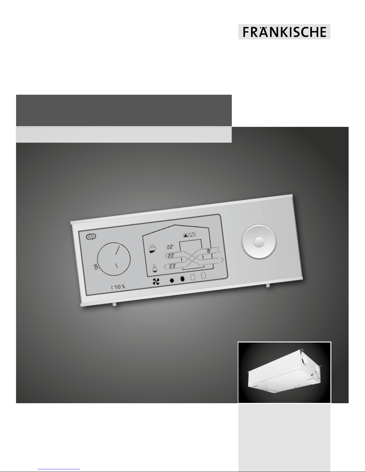
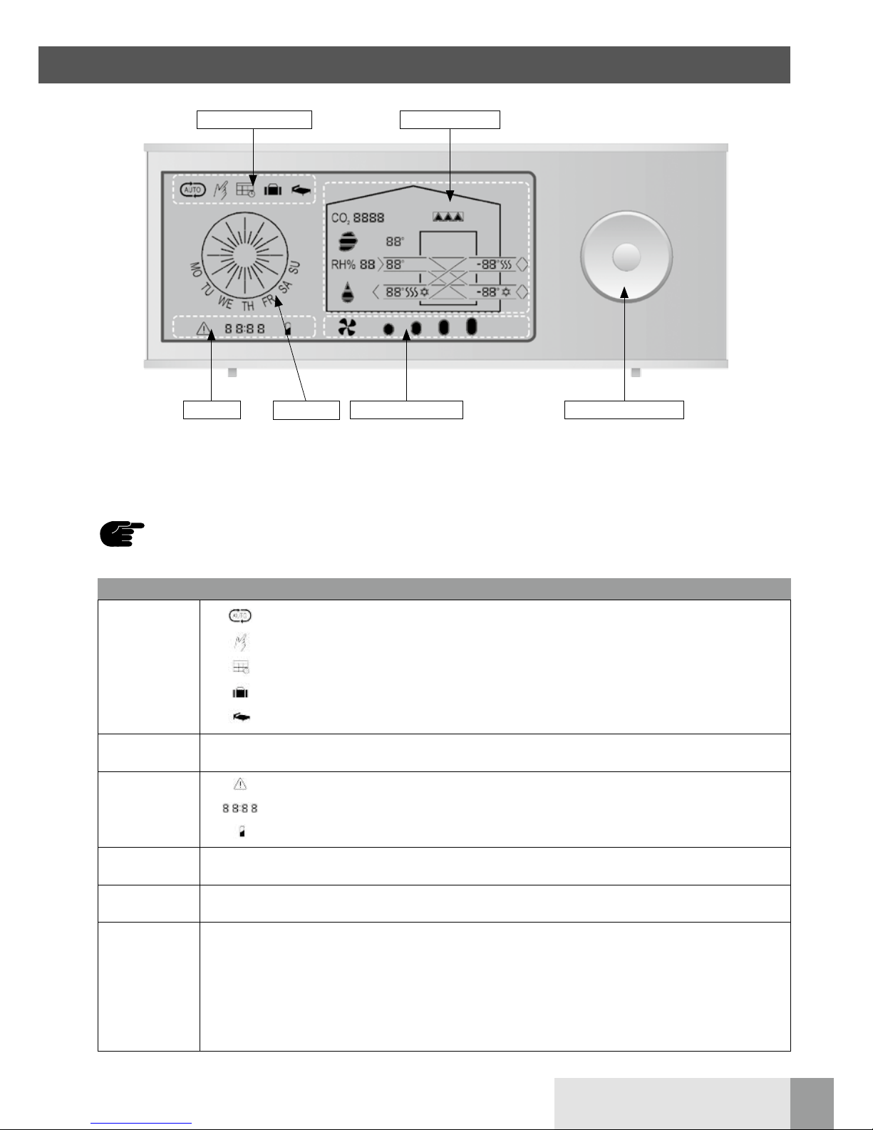
The wireless remote control has
been developed specifically for
demanding operators of profi-air
180 flat ventilation units who
emphasise innovative operation.
The remote control has a wireless
The operating instructions will help
you to operate the wireless remote
control ideally. We therefore recom-
mend reading these operating
instructions carefully. Keep these
operating instructions during the
entire life of the wireless remote
When used as intended, the device
is safe and reliable to operate.
Its construction and design are state
of the art and comply with all the
connection to the control board of
the ventilation unit. The range of
this control unit inside a building
(through walls and light ceiling
structures) is up to 30 m.
control since they also serve as a
reference for service and mainte-
nance work and thus guarantee
smooth and efficient operation.
Considerable care was taken when
preparing these instructions. How-
ever, no legal claim whatsoever can
relevant DIN / VDE regulations and
safety provisions. All safety regula-
tions, warnings and notes of these
operating instructions have to be
Non-authorised changes or modifications of the wireless remote control are forbidden.
be derived therefrom. We also
reserve the right to make alterations
to these instructions at any time and
without notice.
observed; non-observance might
result in personal injury and/or
damage to profi-air 180 flat.
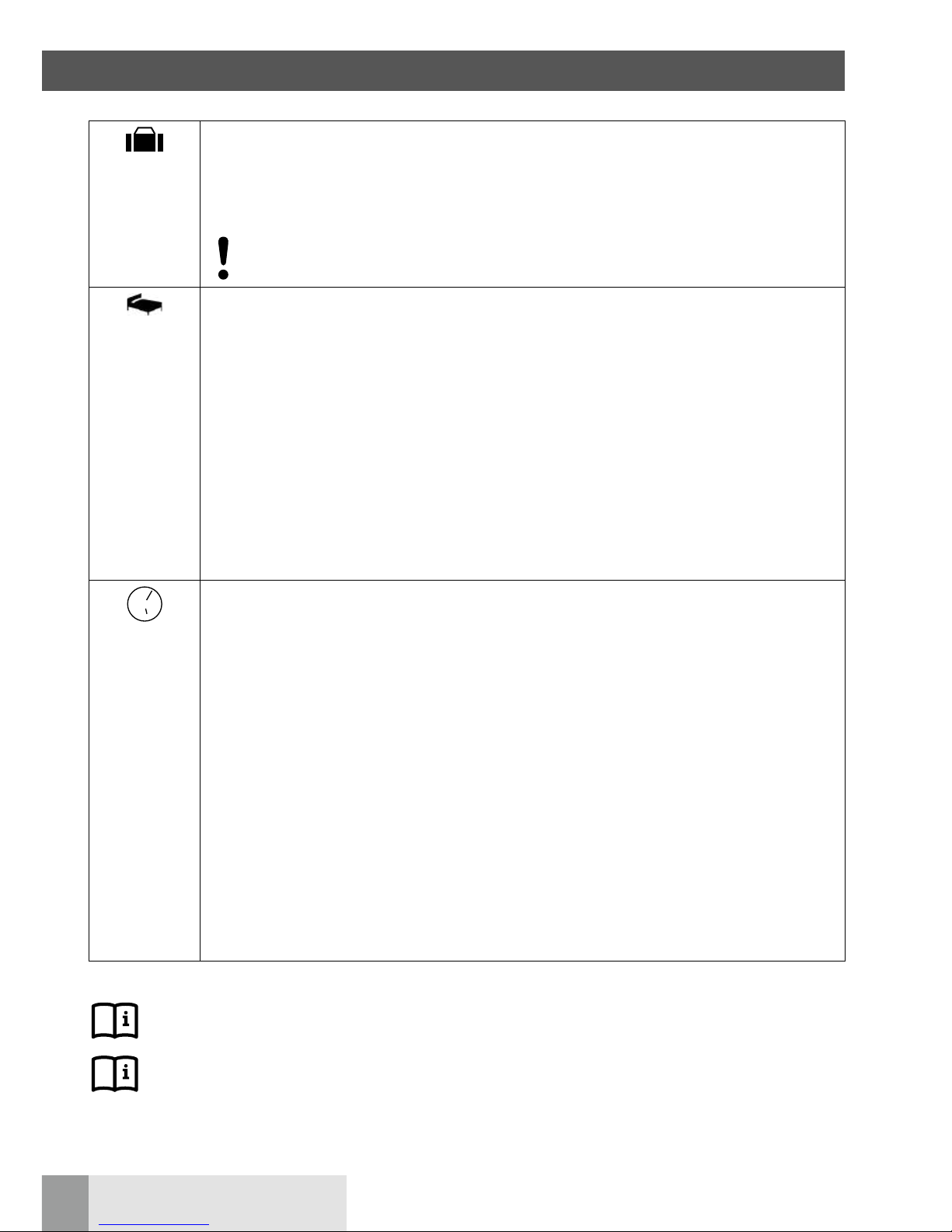
Risk of personal injury
Risk of:
ndamage to equipment
nerrors while operating the device if the instructions are not followed
nother material damage
Additional notes
Reference to other sections and/or guidelines of the manufacturer.
Disposal instructions
1.3 Symbols used

4
FRÄNKISCHE | OI profi-air RC 180 flat
1.4 Intended use
1.5 Transport and unpacking
1.6 Checking the scope of delivery
1.7 Overview of functions
The wireless remote control must
only be used to operate
profi-air 180 flat ventilation units
Please handle the profi-air wireless
remote control with utmost care
during transport and unpacking.
and is only suited for domestic use
inside closed and frost-protected
rooms.
1 General
If the delivered wireless remote
control has any damage or incom-
The wireless remote control features the following functions:
The following can be displayed on the remote control:
The scope of delivery includes: nwireless remote control
n2 x batteries 1.5 V AAA
nUSB cable for optional power supply
noperating instructions
nantenna for installation in profi-air 180 flat
nmanual operation
nweekly autotimer according to stored weekly programs (P1 to P10)
nholiday mode
nnight setback
ntemperature control – summer bypass
nsetting of the time interval for filter exchange
nautomatic demand control depending on relative humidity and/or VOC (optional accessories)
nactivating / deactivating – defroster heating (optional accessories)
nventilation mode
nfresh air, supply air, extract air and room temperature
ntime left until filter replacement
nerror code + alarm signal
nhumidity in the extract air channel (with the humidity sensor installed in profi-air 180 flat)
nair quality in the extract air channel (with the VOC sensor installed in profi-air 180 flat)
pleteness, please get in touch with
the supplier immediately.

5
FRÄNKISCHE | OI profi-air RC 180 flat
2.1 Front
2.2 Back
2 Layout of the wireless remote control
Display
Open battery compartment
Navigation button
Optional USB connection
Fastening points

6
FRÄNKISCHE | OI profi-air RC 180 flat
The remote control and the ventilation unit must be synchronised in order to be able to communicate.
This requires the following steps:
In order to ensure reliable communication between the ventilation unit and the wireless remote control,
the included antenna must be installed in profi-air 180. This requires the following steps:
Up to three wireless remote controls
can be connected to a ventilation
unit. All connected wireless remote
Step Procedure
1Interrupt power supply of the ventilation unit.
2Open the battery compartment on the back of the remote control and insert the included batteries 2 x 1.5 V AAA).
3If you want to establish permanent power supply, connect the included USB cable.
The port for the mini USB connector is on the back of the wireless remote control under the battery cover.
4Re-connect power supply of the ventilation unit. Within the next 60 seconds, the wireless remote control and the
ventilation unit try to establish a connection, after which the unit's data is displayed on the display.
Step Procedure
1Interrupt power supply of the ventilation unit.
2Remove the housing cover of the ventilation unit.
3
Screw the antenna to the connection coupling of the control board and turn it.
For the position of the connection coupling, see profi-air 180 flat installation and operating instructions.
4Re-install the housing cover of the ventilation unit.
If synchronisation does not work at the first attempt (error code E13), either the distance to the control
board of the ventilation unit is too big or the wireless remote control has been synchronised with
another ventilation unit before. You must reset the wireless remote control in this case. Push and hold
the “LEFT” button for approx. 10 seconds until all symbols on the display are flashing. The wireless
remote control can now be synchronised again.
controls are equal, meaning that
always the latest respective change
is applied.
3.2 Synchronisation
3.1 Installation of the antenna
3.3 Multiple wireless remote controls
3 Putting the wireless remote control into operation

7
FRÄNKISCHE | OI profi-air RC 180 flat
The following table provides a short description of the different symbols and buttons of the wireless remote control.
Display fields Function
Operating mode
Automatic mode / demand control
Manual operation
Weekly autotimer
Holiday mode
Night setback
Time/day Use the clock to set the weekly autotimer and night setback.
Info line
Alarm (error code)
Information on various functions or programs
Low battery status
Ventilation mode The four oval fields display the ventilation mode. The more fields are filled, the higher the ventilation mode.
Navigation
button Use this button to select individual menu items from the user menu and to increase or reduce target values.
Operating data
The following information can be displayed:
nfilter replacement
nroom temperature
ntemperature of supply/extract air
nfresh air temperature
nheat recovery / summer bypass
nrelative extract air humidity (optional)
nextract air quality (optional)
ndefroster heating active (optional)
The wireless remote control features a power saving function which switches the display off between
11:00 pm and 07:00 am. You can activate the illumination by pushing any button.
Operating modes
Info line Ventilation mode Navigation button
Time/day
Operating data
4 Display overview

8
FRÄNKISCHE | OI profi-air RC 180 flat
The following table provides an overview of the functions of the navigation button and the keystroke combinations.
Button Function
Push the “CENTER” button to start the user menu, select a menu item or confirm a setting.
Push the “LEFT” and “RIGHT” buttons to switch between the different menu items or to switch the ventilation
mode into manual mode.
Push the “UP” and “DOWN” buttons to switch between menu subitems or to change the set values.
5.1 Navigation button
5.2 Keystroke combinations
5 Navigation button and keystroke combinations
Button Function
Push and hold the “CENTER” button for approx. 3 seconds.
Takes you back to the start page from any menu item.
Push and hold the “DOWN” button for approx. 5 seconds.
Activates/deactivates manual summer bypass for 1 hour.
Push and hold the “UP” button for approx. 5 seconds.
Activates/deactivates fireplace operation for 15 minutes.
Push and hold the “RIGHT” button for approx. 10 seconds.
Activates/deactivates the installation mode.
Push and hold the “CENTER” and “UP” buttons for approx. 10 seconds.
Resets all settings and target values to the factory settings (only possible in activated installation mode).
Push and hold the “LEFT” button for approx. 10 seconds.
Resets the wireless remote control / ventilation unit synchronisation.

9
FRÄNKISCHE | OI profi-air RC 180 flat
6.1 “Operating modes” display field
6 User menu
The user menu is used to control the profi-air 180 flat ventilation unit. It provides possibilities to set,
e.g. operating modes and visualise operating data, filter replacement and error codes.
The user menu is set up as follows:
The following sections describe the individual display fields.
Automatic
mode no
Weekly
program
setting (1–11)
Holiday mode
on/off
Manual
ventilation
mode (1– 4)
Night
setback
on/off
Remaining
filter life
Set filter
replacement
interval
(90–360 days)
Set
time
Set
day
Symbol Description
Automatic mode (only with the humidity sensor and/or VOC sensor installed)
The automatic mode regulates the air volume flow rate of the ventilation unit depending on the humidity level
and/or air quality in the building. A sensor in the extract air channel of the ventilation unit measures the humidity
and/or air quality.
Automatic mode is activated if the symbol is shown on the display. The set ventilation mode is also displayed
there.
We generally recommend operating the ventilation unit in automatic mode since this ensures
constant air exchange as required. The automatic mode additionally prevents the house from drying
out especially during the winter.
Manual operation
In manual operation the user must set the ventilation mode himself/herself if the required air exchange in the
house changes.
Weekly program
The ventilation mode is controlled via the selected profile when a weekly program is activated.
The profile can be changed as follows:
Step Description
1 Start the user menu by pushing the “CENTER” button.
2 Select the weekly program menu item by pushing the “LEFT” or “RIGHT” buttons.
3 Push the “DOWN” button as soon as the weekly program symbol starts flashing. Now, the selected
weekly program, e.g. P1, flashes in the info line.
4 Select the weekly program by pushing the “UP” or “DOWN” buttons.
5 Confirm this by pushing the “CENTER” button.
See Section 9 for a description of the different weekly programs.

10
FRÄNKISCHE | OI profi-air RC 180 flat
Holiday mode
The holiday mode can be activated for times when the building is not inhabited. The ventilation unit runs
with minimum air exchange in holiday mode (i.e. 2/3 of the time in ventilation mode 1 and 1/3 of the time in
ventilation mode 0).
The function is deactivated by choosing another operating mode or after 28 days at the latest.
Deactivate the function immediately after the building is inhabited again since otherwise this causes an
increased risk of condensation in the pipes, or might lead to moisture damage in the building.
Night setback
The ventilation unit runs in ventilation mode 1 with activated night setback.
This function can be used together with automatic mode, manual operation and activated weekly program.
You can set the period for the night setback as follows:
Step Description
1 Start the user menu by pushing the “CENTER” button.
2 Select the night setback menu item by pushing the “LEFT” or “RIGHT” buttons.
3 Push the “DOWN” button as soon as the night setback symbol flashes.
Now, the set start time, e.g. 11:00 pm, flashes in the info line.
4 Select the start time by pushing the “UP” or “DOWN” buttons.
5 Confirm this by pushing the “CENTER” button.
6 Now, the set end time, e.g. 07:00 am, flashes in the info line.
7 Select the end time by pushing the “UP” or “DOWN” buttons.
8 Confirm this by pushing the “CENTER” button.
Time
The time controls weekly programs and night setback.
Set the time as follows:
Step Description
1 Start the user menu by pushing the “CENTER” button.
2 Select the clock menu item by pushing the “LEFT” or “RIGHT” buttons.
3 Push the “DOWN” button as soon as the clock symbol starts flashing.
Now, the set time, e.g. 05:00 pm, flashes in the info line.
4 Set by pushing the “UP” or “DOWN” buttons.
5 Confirm this by pushing the “CENTER” button.
6 Now, the set weekday flashes at the bottom edge of the clock.
nMO – Monday
nTU – Thursday
nWE – Wednesday
nTH – Thursday
nFR – Friday
nSA – Saturday
nSU – Sunday
7 Select the weekday by pushing the “UP” or “DOWN” buttons.
8 Confirm this by pushing the “CENTER” button.
6 User menu
For factory settings and setting options, see profi-air 180 flat installation and operating instructions,
Section 5.
For summer bypass, automatic mode and frost protection control strategies, see profi-air 180 flat
installation and operating instructions, Section 6.

11
FRÄNKISCHE | OI profi-air RC 180 flat
6 User menu
The “operating data” display field displays different operating data depending on the system's current operating
mode and/or the accessories connected. The following table shows and explains the individual items.
Heat recovery active Summer bypass active
(T5)
(T2) T1(8)
(7) T1 (6)
(9)
Symbol for the ventilation unit
(T3)
Symbol Description
(T1) Fresh air temperature / measured in the fresh air channel of the ventilation unit
(T2) Supply air temperature / measured in the supply air channel of the ventilation unit
(T3) Extract air temperature / measured in the extract air channel of the ventilation unit
(T5) Room temperature / measured at the wireless remote control
(6) Defroster heating (optional accessories required)
Display with the profi-air defroster heating DN 125 in operation.
For frost protection mode control strategies, see profi-air 180 flat installation and operating
instructions, Section 6.
(7)
Filter
The triangles of the filter symbol show the remaining life of the filter. If all three triangles are displayed in black,
the filter symbol flashes and the filter should be replaced.
The filter alarm can be intermitted for 14 days by pushing any button on the wireless remote control.
The factory setting for the filter replacement is 180 days. This setting can be extended or reduced depending on
the degree of pollution of the filter.
Proceed as follows to display the remaining filter life or to adapt the interval for filter replacement:
Step Description
1 Start the user menu by pushing the “CENTER” button.
2 Select the filter menu item by pushing the “LEFT” or “RIGHT” buttons.
3 The remaining life of the filter is displayed in the info line as soon as the filter symbol flashes.
4 Push the “DOWN” button to display the filter interval in the info line.
5 Set by pushing the “UP” or “DOWN” buttons.
6 Confirm this by pushing the “CENTER” button.
For filter replacement instructions, see profi-air 180 flat installation and operating instructions and/or
the replacement filter instruction leaflet.
6.2 “Operating data” display field

12
FRÄNKISCHE | OI profi-air RC 180 flat
(8) Relative humidity (optional accessories required)
The drop symbol shows whether the humidity in the building is within the comfort zone.
Symbol Relative humidity Description
< 24 % very dry air
25–34 % dry air
35–65 % comfort zone
> 66 % humid air
The drop symbol is active only if the ventilation unit is furnished with the optional humidity
sensor.
The automatic mode must be activated to control the air volume depending on the humidity.
For automatic mode control strategies, see profi-air 180 flat installation and operating instructions,
Section 6.
(9) Air quality (optional accessories required)
The cloud symbol shows the air quality in the building.
Symbol Relative humidity Description
< 800 ppm very good air quality
800–1,200 ppm good air quality
1,200–1,500 ppm sufficient air quality
> 1,500 ppm poor air quality
The cloud symbol is active only if the ventilation unit is furnished with the optional VOC
sensor.
The automatic mode must be activated to control the air volume depending on the air quality.
For automatic mode control strategies, see profi-air 180 flat installation and operating instructions,
Section 6.
6 User menu

13
FRÄNKISCHE | OI profi-air RC 180 flat
6 User menu
Symbol Description
Alarm
The alarm symbol means that there is a malfunction in the ventilation unit.
The error code is displayed after the symbol.
See Section 8 for a list of error codes.
For more troubleshooting information, see profi-air 180 flat installation and operating instructions.
Information regarding time setting, weekly programs, error codes, etc. is displayed here.
Display Meaning
A1 A1 automatic program is selected
P1, P2 … Weekly program number
BYP1 Manual summer bypass is activated, 1 h left
DEF Defroster function active
E1, E2 … Error code
Low battery status in the wireless remote control
The info line displays error messages, information on different settings of the ventilation unit and the battery status
of the wireless remote control.
6.3 “Info line” display field

14
FRÄNKISCHE | OI profi-air RC 180 flat
6.4 “Ventilation mode” display field
This display field displays the current ventilation mode.
Mode 0
The device is switched off. This function may only be used in exceptional cases, e.g unpleasant odour from
outside. After activating mode 0, this will be enabled for 4 hours and switched to mode 3 afterwards.
If the system has been switched off over a longer period of time, this causes an increased risk
of condensation in the pipes, and/or might lead to moisture damage in the building.
Mode 1 (protection against moisture)
The lowest fan speed protects the building from moisture during times of longer absence of the inhabitants
(e.g. holidays).
49 % of the set fan speed in mode 3.
Mode 2 (reduced ventilation)
The low fan speed is used for reduced ventilation during times of absence of the inhabitants.
70 % of the set fan speed in mode 3.
Mode 3 (rated ventilation)
The normal fan speed is used for rated operation of the ventilation unit when the inhabitants are present.
Can be set between 46 % and 91 % of fan speed.
Mode 4 (intensive ventilation)
The maximum fan speed is used for intensive ventilation (party mode).
After activating mode 4, this will be enabled for 4 hours and switched to mode 3 afterwards.
Can be set from ventilation mode 3 to 100 % of the fan speed.
6 User menu

15
FRÄNKISCHE | OI profi-air RC 180 flat
The fitter menu is used to commission the profi-air 180 flat ventilation unit.
Push and hold the “RIGHT” button for 10 seconds to activate the fitter menu. The unit symbol starts flashing slowly
and the control switches to ventilation mode 3. You can also access the fitter menu by pushing and holding the
MANUAL and AUTO buttons at the control unit for 5 seconds.
The fitter menu remains active for 60 minutes or until you push the same combination of buttons for a restart.
Only experts and service technicians who have familiarised themselves comprehensively with the
ventilation unit may use the fitter menu. Wrong settings may lead to device and/or building damage.
For commissioning information, see profi-air 180 flat installation and operating instructions, Section 4.
The fitter menu is set up as follows:
Software
status of the
heat recovery
ventilation
device H___
Software
status of the
remote
control F___
Software
status of
accessories
A___
Automatic
program
Automatic
program
setting (A1…)
Set the sensitivity
of the humidity
sensor (accessories)
(35–65 % RH)
Speed of the
supply air fan
Read the speed of
the extract air fan
Display
summer bypass
target value
Read target
values of
preheating
(accessories)
Summer bypass
target value Tmin
(T1) set fresh air
temperature
Preheating
(accessories)
on/off
Summer bypass
target value Tmax
(T3) set fresh air
temperature
7 Fitter menu

16
FRÄNKISCHE | OI profi-air RC 180 flat
7 Fitter menu
The menu item displays the software versions of the different components in the info line.
Display Description
H… Software version of the mainboard in the ventilation unit
F… Software version of the wireless remote control
A… Software version of the connection box
7.1 SW menu item
7.2 Automatic mode menu item (optional accessories required)
This menu item displays the automatic program and the target value for relative humidity.
Display Description
Operating
modes
display field
Info line
display field
A1
Operating data
display field
The selected automatic program is displayed (only A1 available with profi-air 180 flat)
You can set the humidity target value as follows:
Step Description
1 Push and hold the “RIGHT” button for approx. 10 seconds to start the fitter menu.
2 Push the “CENTER” button to display the A1 automatic program and the currently measured value.
3 Push the “CENTER” button to display the humidity target value (display flashes rapidly).
4 Set by pushing the “UP” or "DOWN" buttons.
5 Confirm this by pushing the "CENTER" button.
6 Push and hold the “RIGHT” button for approx. 10 seconds to end the fitter menu.
If a set target value is too low, this can compromise the well-being of the inhabitants and/or lead to certain
materials in the building drying out.
If a set target value is too high, this can compromise the well-being of the inhabitants and/or lead to
moisture damage in the building.
The menu item displays the current fan speed in mode 3.
Display Description
Ventilation mode
display field
Info line display
field
Current fan speed
Operating data
display field
Flashing supply
air channel
Flashing extract
air channel
Proceed as follows to display fan speed:
Step Description
1 Push and hold the “RIGHT” button for approx. 10 seconds to start the fitter menu.
2 Select the fan menu item by pushing the “RIGHT” button until the fan symbol starts flashing.
If the fan symbol and the supply air channel are flashing, the info line shows the fan speed of the
supply air fan.
3 Push the “DOWN” button to display the extract air fan.
If the fan symbol and the extract air channel are flashing, the info line shows the fan speed of the
extract air fan.
4 Push and hold the “RIGHT” button for approx. 10 seconds to end the fitter menu.
7.3 Fan menu item

17
FRÄNKISCHE | OI profi-air RC 180 flat
7 Fitter menu
7.5 Summer bypass menu item
You can set the desired target temperatures for the summer bypass under this menu item:
Summer bypass active
(T1 / set bypass Tmin)
Symbol for the ventilation unit(T3 / set bypass Tmax)
7.4 Defroster heating menu item (optional accessories required)
This menu item activates / deactivates the defroster heating:
Defroster heating symbol
Symbol for the ventilation unit Defroster heating activated / deactivated
Step Description
1Push and hold the “RIGHT” button for approx. 10 seconds to start the fitter menu.
2Select the defroster menu item by pushing the “RIGHT” button until the defroster heating symbol starts
flashing.
3Push the “CENTER” button to display the current setting.
4
Push the “UP” or “DOWN” buttons to activate or deactivate the defroster heating.
“ON” – defroster heating activated
“OF” – defroster heating deactivated
5Confirm this by pushing the “CENTER” button.
6Push and hold the “RIGHT” button for approx. 10 seconds to end the fitter menu.
For defroster heating control strategies, see profi-air 180 flat installation and operating instructions,
Section 6.

18
FRÄNKISCHE | OI profi-air RC 180 flat
7 Fitter menu
Step Description
1Push and hold the “RIGHT” button for approx. 10 seconds to start the fitter menu.
2
Select the summer bypass menu item by pushing the “RIGHT” button until the summer bypass is displayed as
shown above. The ventilation unit symbol flashes.
The displayed temperatures still equal the currently measured values.
3Push the “CENTER” button to display the T1 / set bypass Tmin and T3 / set bypass Tmax target values.
4
Push the “CENTER” button to set the T1 / set bypass Tmin target value. The T1 target value flashes and
can be changed by pushing the “UP” and “DOWN” buttons (8 to 15 °C range).
Confirm this by pushing the “CENTER” button again.
5
After confirming the last setting, the T3 target value flashes and can be changed by pushing the “UP” and
“DOWN” buttons (22 to 30 °C range/”OF”)
The summer bypass is deactivated permanently if the target value is set to “OF”.
Confirm this by pushing the “CENTER” button again.
6Push and hold the “RIGHT” button for approx. 10 seconds to exit the fitter menu.
For summer bypass control strategies, see profi-air 180 flat installation and operating instructions,
Section 6.
The following table shows the target values and setting ranges which can be adapted using the wireless remote
control.
You can reset the ventilation unit to the factory settings from the fitter menu. Push and hold the “UP” and
“CENTER” buttons at the same time for approx. 10 seconds until the entire display flashes.
Designation Factory setting min. max.
Humidity
automatic mode (RH %) 45 % 35 % 65 %
Summer bypass Tmin
Fresh air temperature (T1) 15 °C 8 °C 15 °C
Summer bypass Tmax
Extract air temperature (T3) 24 °C 22 °C / OF 30 °C
Defroster heating OF OF ON
Filter replacement interval 180 days 90 days 360 days
7.6 Target values and setting ranges
7.7 Reset to factory settings

19
FRÄNKISCHE | OI profi-air RC 180 flat
Code Description
E1 Extract air fan
E2 Supply air fan
E3 Summer bypass flap
E4 Fresh air temperature sensor (T1)
E5 Supply air temperature sensor (T2)
E6 Extract air temperature sensor (T3)
E7 Exhaust air temperature sensor (T4)
E8 Room air temperature sensor (T5)
E9 Humidity sensor
E10 Fresh air temperature < –13 °C
E11 Supply air temperature < 5 °C
E12 Fire protection; one sensor measures a temperature > 70 °C
E13 Communication error
For more troubleshooting information, see profi-air 180 flat
installation and operating instructions.
8 Error codes

20
FRÄNKISCHE | OI profi-air RC 180 flat
Weekly program P1
Weekly program P2
Monday – Friday
Time /
mode
0–1
1–2
2–3
3–4
4–5
5–6
6–7
7–8
8–9
9–10
10–11
11–12
12–13
13–14
14–15
15–16
16–17
17–18
18–19
19–20
20–21
21–22
22–23
23–24
4
3
2
1
Weekend
Time /
mode
0–1
1–2
2–3
3–4
4–5
5–6
6–7
7–8
8–9
9–10
10–11
11–12
12–13
13–14
14–15
15–16
16–17
17–18
18–19
19–20
20–21
21–22
22–23
23–24
4
3
2
1
Weekly program P3
Monday – Friday
Time /
mode
0–1
1–2
2–3
3–4
4–5
5–6
6–7
7–8
8–9
9–10
10–11
11–12
12–13
13–14
14–15
15–16
16–17
17–18
18–19
19–20
20–21
21–22
22–23
23–24
4
3
2
1
Weekend
Time /
mode
0–1
1–2
2–3
3–4
4–5
5–6
6–7
7–8
8–9
9–10
10–11
11–12
12–13
13–14
14–15
15–16
16–17
17–18
18–19
19–20
20–21
21–22
22–23
23–24
4
3
2
1
9 Weekly programs
Other manuals for profi-air 180 Flat
3
Table of contents
Other FRÄNKISCHE Remote Control manuals