Fracarro 3DG-4ASI-4T User manual

3DG-4ASI-4T
OPERATING INSTRUCTIONS

2
English
The product can only be installed by qualied personnel in compliance with local safety laws and regulations. Fracarro
Radioindustrie is free from all civil and criminal responsibility due to breaches of current legislation derived from the improper
use of the product by the installer, user or third parties
The product must be used in full compliance with the instructions given in this manual, in order to protect the operator against
all possible injury and the product from being damaged.
Never remove the product cover as there are live parts underneath it
Installation precautions
• The product must not be exposed to water drips and must be installed indoors inside in dry places.
• Damp and condensation drops could damage the product. Consequently always wait for the product to
be perfectly dry before use. Handle with care. Knocks could damage the product. Leave plenty of space
around the product to ensure sufcient ventilation. High temperatures or overheating could compromise
the product functions and life.
• Do not install the product above or close to sources of heat, in dusty atmospheres or when it could be
exposed to corrosive substances.
• If the product is installed on the wall, use proper expansion bolts suitable to the xing support. The wall and
the xing support must be able to bear at least 4 times the equipment weight.
• Attention: to avoid being hurt, the unit must be mounted to the wall/oor according to the installation
instructions.
• The “PERMANENTLY INSTALLED EQUIPMENT” needs a sectioning device, easy to access, that must be
integrated outside the unit; in the “EQUIPMENT WITH POWER PLUG”, the plug must be installed close to the
equipment and easily accessible.
• The unit must be connected to the ground electrode of the antenna system, in compliance with the EN
60728-11 standard. The earth screw is indicated with the symbol: .
• It is important to observe the provisions of the EN60728-11 standard and not to connect this screw to the
power supply earth line.
Class II symbol Ground symbol of the antenna system
GENERAL PRECAUTIONS
In case of a malfunction, do not attempt to repair the product because this would invalidate the guarantee.
Only use the feeder supplied with the product. The information given in this manual has been carefully prepared, however
Fracarro Radioindustrie S.r.l. reserves the right at any time, and without prior notice, to make any Improvements or changes
to the product described in the manual. Consult the website of www.fracarro.com for the terms regarding assistance and the
guarantee.
2. INTRODUCTION
The 3DGFLEX family is a modular headend equipped with a cabinet (3DG-BOX cod.283156) that can house 6 modules and a
Control Unit in order to use and program the centralised unit.
The control unit allows:
- Powering up to 6 modules
- Programming the central unit using the keypad and display on board, or through a Web interface (PC) from a local or
remote network.
- Monitoring in real time the state of the central unit and send signals via email (Controller Host).
- Importing or exporting the central unit conguration via USB.
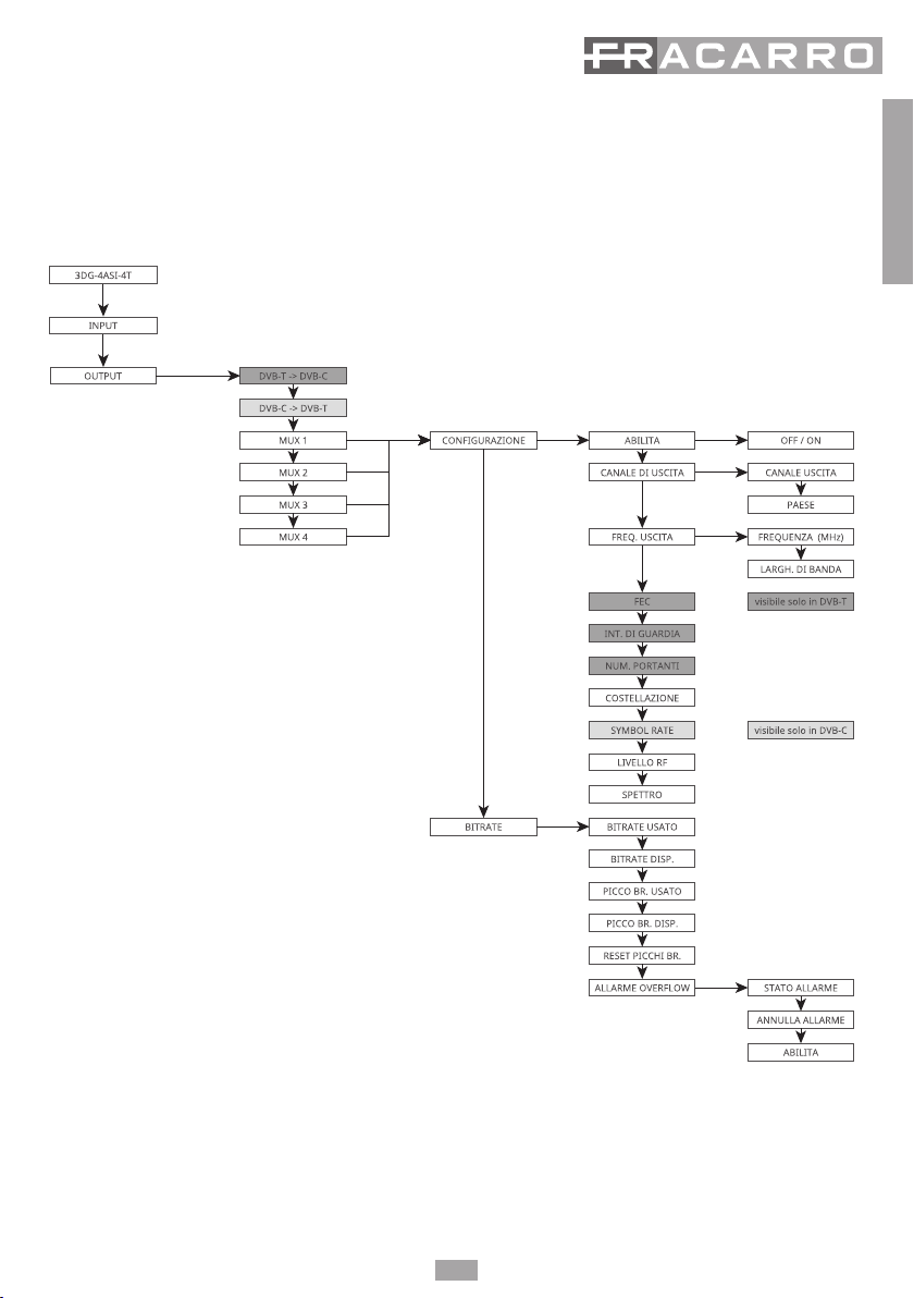
3DG-4ASI-4T is a module to house in the 3DGFLEX central unit, that generates two pairs of adjacent Multiplexes modulated
according to the DVB-T or DVB-C standards, using the streams received from any RF or USB Input In the same module or any
other module in the central unit cabinet (POOL Technology - see Chapter 2.3).
1. SAFETY WARNINGS

3
English
Full band modulator: the mux can be modulated on arbitrary frequencies on VHF-S-UHF bands (114 - 858 MHz).
NB: the four mux are not totally independent, but linked to pairs (MUX 1-MUX 2 and MUX 3-MUX 4), channel (or frequency)
parameters, band width and output level: if the output channel of MUX 1 (or MUX 3) is set the output channel of MUX 2 (or
MUX) will be set automatically to the adjacent channel subsequent to the one set for MUX 1 (or MUX 3). However, If the output
channel is set for MUX 2 (or MUX 4) the output channel will be automatically set for MUX 1 (or MUX 3) to the adjacent previous
channel. In the same way, by setting a different bandwidth level or output level for MUX 1 (or MUX 3) the same value will be set
for MUX 2 (or MUX 4) and vice versa.
Each module has 4 satellite inputs (INPUT 1, INPUT 2, INPUT 3 and INPUT 4) and double slot common interface associated with
any of the module inputs connected in the central unit (POOL technology - see chapter 2.3), which allows decrypting programs
from the same transport stream.
There Is also a USB port to rapidly update the rmware, download and update conguration parameters or to read and
modulate videos in .TS les.
It can be programmed in two of the following ways: base programming using the keypad and LCD display on the control unit,
or complete programming using the web interface connecting with a local or remote PC connected to the LAN port/network
of the control unit. Each 3DG-4ASI-4T module can generate, for each 14/18V input, the tone at 22 KHz and the tone-burst
DISEqC 1.0 to pilot any multiswitches or LNB, and is equipped with short-circuit protection.
The maximum remote power current for the module is 500mA@14V/18V total.
2.1 Module description
Fixing screws
Input connectors (IN1, IN2)
Standard ASI.
Output connectors (OUT1, OUT2)
Standard ASI.
Multicolor LED:
indicates the input/output status
Factory Default Button.
Use only if it is really necessary:
carry out the factory default via software
USB port
Multicolor LED indicating
the module status
Fixing screws
2. PRODUCT DESCRIPTION

4
English
2.2 Led description
LED INPUT STATUS
INPUT LED INDICATION
off Input not activated
Orange Input active, waiting for lock
Green Input active and locked
LED STATUS
Colour INDICATION
On turning on/initialising the system
Orange Internal boot loader or warning of overow
Red Run operating system
Flashing green Boot phase
Green System started without error
System started
Green Normal
Red Anomaly alarm
Flashing red Update or Recovery phase
2.3 POOL Technology
The 3DG-4ASI-4T module is part of the evolved 3DGFLEX family. The main innovation is the use of POOL
technology. POOL technology enables total communications between all the EVO modules in the 3DGFLEX.
Communications are two-way and, in fact, any interactive content can be managed and used on any module.
For example: each module can modulate in output any input from any module in the central unit.
This technology enables noteworthy savings in the module resources (e.g. no input with the same frequency)
and greater exibility (the output mux can be composed from any content received in the central unit).

5
English
3. INSTALLATION OF THE PRODUCT
3.1 PACKAGE CONTENTS
The packaging contains the following items:
• 3DG-4ASI-4T module
• Safety warnings and product
installation instructions.
3.2 MOUNTING THE MODULE
To avoid any injury, the product must be installed in a basket in accordance with the assembly instructions.
3.2 FIXING THE MODULE
Fix the module with the provided screws.
To guarantee correctoperationof the modules and to ensure suitable shielding against radiointerference,
it is necessary to x the module with the provided screws.
4. INSTRUCTIONS FOR USE
1. Insert the module in the central unit (which must be turned off).
2. Turn on the central unit and wait for initialisation (the Fracarro logo appears on the display).
3. Connect the antennal cables to the respective inputs.
4. To access the menu, press “√ ”, type in the user code (default 1234) and conrm by pressing “√”; the central
unit will perform a scan to nd the connected modules. Begin programming using the PC or keypad and
integrated display in the control unit.
5. Check the output signal using a eld meter.
6. Connect the distribution cable to the central unit output connector.
If required, the module can be reset to the factory default settings (see the control unit instructions).
ATTENTION: In this case the default language is English.
Carefully insert into the housing guide
Top screw
Lower screw

6
English
5. PROGRAMMING INSTRUCTION
Note: the control unit time out is 5 minutes, after this time lapse since the last change the CU resets the module
conguration to the last save.
5.1 BASIC PROGRAMMING FROM THE CENTRAL UNIT
The 3DG-4ASI-4T module can be programmed using the keypad on the central control unit.
To access the programming menu, press “√” and type in the user code (default 1234).
To change the menu language on the 3DG-4ASI-4T access the main LANGUAGE menu of the control unit, select
the required language and press √.
For all the programming activities and to interpret the programming menus in the following owchart, refer to
the following key table:
Keyboard Keyboard and Key function
or Conrms an entered value or enters the menu/submenu
or Erases an entered value or leave the menu
Are used to navigate the various menu items
Modify the parameters
Enter values
Saves the changes
S
......
9
WXYZ
0
➤
➤
➤
➤
✗
➤
✓➤
➤
➤
5.1.1 INPUT MENU: Allows selecting one of the 3 available inputs to be programmed (see the Flowchart)
INPUT FLOWCHART
- INPUT 1, INPUT 2
• ENABLE:enable or disable the selected input;
• MEASURE: contains all the information relevant to the signal received from the selected input.
• LOCK: checks if the receiver has LOCKED the signal.
• NETWORK NAME: displays the transponder name (this parameter cannot be changed).
- INPUT USB: to manage the USB input as source for an audio/video signal in transport stream.
• ENABLE: allows activating the reading of audio/video les in an external USB drive.
• SELECT FILE: select which le to use among those stored in the external USB drive.
• USB STATUS: shows the status of the selected le.

7
English
NOTE: 3DG-4ASI-4T recognises and produces audio/video les only in .TS format, with an average bandwidth
no greater than 15 Mbps; any other audio/video format must be converted into the correct .TS format by using
software tools that can be found in the web.
5.1.2 OUTPUT MENU:to congure the DVB-T/DVB-C output signal from the 3DG 4ASI 4T module.
OUTPUT FLOWCHART
-DVB-T->DVB-C, DVB-C->DVB-T: the output signal standard can be selected from DVB-T and DVB-C, and
depending on the standard that is set certain specic MUX parameters output can be viewed and changed.
For example: by pressing √ in DVB-C -> DVB-T and, when requested, conrm by pressing the √ key again, the
output standard changes from DVB-C as currently set, to DVB-T, thus enabling to check and change just the
parameters related to it.

8
English
- MUX 1, MUX 2, MUX 3, MUX 4: select which output MUX to congure by setting the various submenus.
• CONFIGURATION: sets all the output MUX parameters.
• ENABLE: enables the selected MUX; by setting the parameter OFF, the MUX is turned off
• OUTPUT CHANNEL:
• OUTPUT CHANNEL: set the output channel where the MUX will be modulated; this parameter
automatically changes the value of the adjacent MUX channel in the same pair.
• COUNTRY: select the country for the channelling standard.
• OUTPUT FREQ.:
• FREQUENCY (MHz): set the output frequency where the MUX will be modulated; this parameter
automatically changes the value of the adjacent MUX frequency in the same pair.
• BANDWIDTH: select the bandwidth from the available ones (7 MHz, 8 MHz, 6MHz); this parameter
automatically changes the bandwidth value of the adjacent MUX in the same pair.
• FEC: set the FEC (Forward Error Connection) parameter from the available ones (1/2, 2/3, ¾, 5/6,
7/8) [only DVB-T]
• GUARD INTERVAL: set the guard interval from the available ones (1/4, 1/8, 1/16, 1/32) [only DVB-T]
• CARRIER NUMBER: set the carrier number between 2K and 8K [only DVB-T]
• CONSTELLATION: set the constellation used to module the carriers from among QPSK, 16QAM and
64QAM [in DVB-T] or 16QAM, 32QAM, 64QAM, 128QAM and 256QAM [in DVB-C]
• RF LEVEL: regulate the output level in dBuV, at steps of 1 dBuV; this parameter automatically changes
the level value of the adjacent MUX in the same pair.
• SPECTRUM: set the spectrum (NORMAL or INVERTED) according to the reception instrument, that
can only work in one of the following two ways; normally NORMAL is set.
• BITRATE: shows the measures of the bitrate in the multiplex of output programs.
• BITRATE USED: indicates the bitrate used. This parameter refers to the total measure of all the
programs added to the output program list.
• BITRATE AVAILABLE: indicates the available bitrate. This parameter refers to the total measure of
the available output bitrates after inserting one or more programs.
• BR PEAK USED: measures the maximum peak bitrate (bit/s) used by the programs in the output
MUX.
• BR PEAK AVAILABLE: measures the total peak bitrate (bit/s) available in the output MUX.
• RESET BR PEAK: to reset the peaks to the initial values calculated according to the digital modulation
settings. After a bitrate overow, when the peaks have reached their limit value, this function has to
be used.
• OVERFLOW ALARM: manages the bitrate overow alarms.
• ALARM STATUS: shows if a bitrate overow has occurred.
• RESET ALARM: cancels the overow alarm. With this function the product is reset on the standard
working conditions (the red LED is turned off).
• ENABLE: to enable (set to ON) the overow alarm signal function. If the function is set on OFF the
option is disabled.

9
English
5.1.3 ASI OUTPUT:to congure the ASI output signal from the 3DG 4ASI 4T module.
OUTPUT FLOWCHART
- ASI 1, ASI 2
• ENABLE:enable or disable the selected output
• BITRATE: shows the measures of the bitrate in the multiplex of output programs.
• BITRATE USED: indicates the bitrate used. This parameter refers to the total measure of all the programs
added to the output program list.
• BITRATE AVAILABLE: indicates the available bitrate. This parameter refers to the total measure of the
available output bitrates after inserting one or more programs.
• BR PEAK USED: measures the maximum peak bitrate (bit/s) used by the programs in the output MUX.
• BR PEAK AVAILABLE: measures the total peak bitrate (bit/s) available in the output MUX.
• RESET BR PEAK: to reset the peaks to the initial values calculated according to the digital modulation
settings. After a bitrate overow, when the peaks have reached their limit value, this function has to be used.
• OVERFLOW
ALARM: manages the bitrate overow alarms.
• ALARM STATUS: shows if a bitrate overow has occurred.
• RESET ALARM: cancels the overow alarm. With this function the product is reset on the standard
working conditions (the red LED is turned off).
• ENABLE: to enable (set to ON) the overow alarm signal function. If the function is set on OFF the option
is disabled.

10
English
5.1.4 PROGRAMS MENU:to congure the output signal from the 3DG 4ASI 4T module.
PROGRAM FLOWCHART
ITALIA / FRANCIA / GERMANIA / UK
AUSTRALIA / FRANSAT / CUSTOM
-MUX 1, MUX 2 , MUX 3, MUX 4: to select the MUX to be congured.
• ALL PIDS: to enable or disable the setting to one of the inputs or CAMS.
• ORDER LIST: to set the order criteria for the programs list.
• INPUT: ordered by classication to the input number.
• LCN: ordered by LCN, i.e. according to the number associated to the program, independently from the
source input.
• PRIORITY: ordered by priority, or according to the position number associated to the program.
• PROGRAMS LIST: set the list of output channels.
• ADD: add the selected program to the list of output programs, once added, the program is marked with an
‘A’ before the name in the channel list.
• DELETE: delete the selected program from the output programs list.
• POSITION: to set the priority and, therefore, the program position in the list of output programs.
• LCN: set the program LCN. The available values are between 0 and 999. Value 1000 means the LCN Is
deactivated.
• BAND: allows monitoring the program bitrate using the following parameters:

11
English
• MONITOR: to enable/deactivate the program bitrate monitoring if it has not been added to the
channel list. According to the program bitrate, it checks whether the program has been included in
the output mux or not.
• AVERAGE VALUE: shows the average program bitrate value.
• PEAK VALUE: to display the program peak bitrate value.
• PROGRAM PROP.: to display useful data about the programs.
• PROGRAM NAME: to display the program name,
• PROVIDER NAME: to display the provider name
• INPUT: to display the program input origin.
• PROGRAM TYPE: to display the program type (TV, RADIO,…).
• SERVICE ID: to display the program service ID.
• ADVANCED CONFIGURATION
• SELECT COUNTRY: to select the installation country.
• TSID: to display and change the ID associated to the transport stream by the broadcaster.
6 WEB INTERFACE
The 3DGFLEX can easily be programmed using the WEB interface, which can be accessed from the PC browser.
It is very important not to congure the 6 modules by using 6 different browsing boards at the same time, as
the CU does not respond to multiple parameter requests from the web, rather it takes the last window opened
as priority and the only one working.
IMPORTANT: in order to access web interface programming, the CU has to be outside the panel menu (logo
3DGex Fracarro shown on the display).
NOTE: the WEB interface could be altered depending on the rmware release loaded in the module.
6.1 WEB INTERFACE CONNECTION
This is the procedure to access the web interface:
1. Connect the PC to the central unit using a RJ-45 CAT-5E cable or passing through a switch.
2. Change the PC or central unit IP address so they are compatible in the same subnet (so they can
communicate).
Example:
a. Parameters set in the properties of the PC Ethernet card:
IP: 192.168.0.3
SUBNET MASK: 255.255.255.0
GATEWAY: 192.168.0.1
b. Parameters to set in the control unit
IP: 192.168.0.2
SUBNET MASK: 255.255.255.0
GATEWAY: 192.168.0.1
3. Start the internet browser (recommended browsers: Google Chrome, Mozilla);

12
English
4. In the address bar type in the IP address associated with the 3DGex; the initial screen is displayed (g. 1).
Type in the username and password to access the web interface home page.
DEFAULT:
USERNAME: admin
PASSWORD: 1234
6.2 HOME MENU
When the web interface is accessed, the conguration menu is displayed with the following Home Page (Fig 2):
In the 3DGFLEX home menu the general state of the CU is displayed.
Select the language for the web interface from among English, German, Italian and French.
The rst module is the 3DG-CU control unit (refer to the CU manual for setting the CU parameters including
network parameters), and the other modules from position 1 to 6 may or may not be displayed. < >.
If the module is in this window, we can view its status.
To be precise, module 3DG-4ASI-4T gives:
The symbol √ if the enabled inputs include the signal and the receiver locks.
The symbol < > if at least one of the enabled inputs does not have a signal or the receiver does not lock.
The symbol < > is also shown If there is a bitrate overow.
Each input (INPUT1, INPUT2 and USB) of the installed modules has a led indication showing the status:
• GREEN: the input is enabled and the receiver tuner is locked (USB: enabled and le read correctly).
• YELLOW: the input is enabled but the receiver is not locked (USB: le missing, not selected or incompatible).
• RED: the input is overloaded (remote power).
• GREY: the input is not enabled.
Fig 1
Fig 2

13
English
The output MUX also have a led indicator showing the status:
• GREEN: MUX in normal working condition.
• DARK GREEN: the MUX is activated but overow monitoring is enabled.
• GREY: the MUX is off
• RED: the MUX has recorded a bitrate overow.
6.3 STATUS MENU
In the 3DGFLEX ‘HOME’ menu, select one of the modules to access its programming.
You can go back to the Home page at any time by clicking on the key on the toolbar at the top of the screen.
The module programming opens with the status window (Fig. 3).
The STATUS menu allows checking the product software release and relative serial number.
The INPUT section gives the status of all inputs, showing the main data of the level parameters and reception
quality (CBER and MER), plus the name and number of the received channel.
Each input also has a led indication that shows the input status, with the following signals:
• GREEN: the input is enabled and the receiver is locked (USB: enabled and le read correctly).
• YELLOW: the input is enabled but the receiver is not locked (USB: le missing, unselected or incompatible).
• RED: input current overload (remote power).
• GREY: the input is not enabled
The OUTPUT section gives the status of the 4 output MUX, displaying the channel and the output frequency,
the RF level, the total bitrate used by the inserted programs and the bitrate available for the MUX. This data Is
given in both numerical and graphic form using the horizontal format bar: the GREEN part of the bar shows the
instantaneously used bitrate, the GREY part shows the maximum peak and the WHITE part shows the bitrate
that is still available.
There is also the RESET PEAK button to reset the peak level and the overow details.
Each output MUX also has a led indication that shows the MUX status, with the following colours:
• GREEN: the MUX is in normal working conditions.
• DARK GREEN: the MUX is activated but overow monitoring is deactivated.
• GREY: the MUX is off.
• RED: the MUX has recorded a bitrate overow.
NOTE: the input and output sections can be scrolled by using the prev. and next keys, or by dragging to the right
and left screen with the mouse pointer. The bitrate overow alarm is shown by the red dot.
Fig 3

14
English
6.4 INPUT MENU
Select one of the inputs or use the status bar and dropdown menu (Conguration/Input/Input no.) to access
the conguration screen.
Fig. 4 shows the input programming menu:
• ENABLE: Checkbox to enable the receiver. It is advisable to deactivate any inputs that are not used in order
to save more energy.
Click on SAVE to save the settings.
The right section shows the detailed information relative to the transponder locking status, the signal quality and
the transport stream received.
CLICK ON “SAVE” TO STORE THE CHANGES.
6.5 USB INPUT MENU
The product allows distributing a user transport-stream from a .TS le: the programs in the specied le are
included in the program list and can be distributed in the output MUX together with the programs received
from the input tuners.
The .TS le can be created from a generic audio-video le, using specic conversion tools which can be
downloaded from the internet. To be reproduced, the le has to be stored in an external USB drive (ash key
or hard disk) and formatted in the le system FAT32.
Fig 4

15
English
To use the USB functions, connect the USB drive to the 3DG-4ASI-4T module and enter the conguration
window of the USB from the status screen or using the menu CONFIGURATION -> INPUT -> USB (Fig.5)
Flag the ENABLE box to enable reading the USB drive.
Select the required le in SELECT FILE and click on SAVE to save the conguration.
If the le has never been used, the system analyses the le format and the bitrate used to perform an
automatic conguration, after which the system creates and saves a le in the USB drive with the same name
but an .FR extension, to make future use more uid.
In the right section, the lock led should turn on green to show that the le is being successfully read. The
transport stream data are shown in the elds on the bottom right. During the pre-analysis, which can take a
few minutes, the USB status is “uploading”.
When a le is started and the “File OK” green led status is shown, the programs in the selected le are added
to the input programs list, and they can also be added to the output programs list.
6.6 OUTPUT MENU
Using the “OUTPUT” menu click on CONFIGURATION -> OUTPUT -> MUX 1 / MUX 2 / MUX 3 / MUX 4 to access the
Multiplex conguration page.
Fig 5
Fig 6

16
English
In this menu the MUX output parameters from the central unit can be changed.
• STANDARD: the modulation standard for the output MUX (DVB-T or DVB-C)
• MODULATOR FREQUENCY: the modulator output frequency can be set according to the frequency in MHz
or by channel according to the standard channelling in the different countries.
NOTE: the output MUX are not independent but are linked to other pairs by the following parameters: output
frequency, bandwidth and output level. Therefore, when these parameters are changed In a multiplex, the
settings of the other mux In the same pair are also Immediately changed. The 2 pairs are divided: MUX1-MUX2
and MUX3-MUX4.
• RF LEVEL: to set the output power in dBuV, in the range foreseen by the technical specication (75 - 95 dbuV).
Below are a few parameters relative to the DVB-T modulation standard:
FEC (1/2 ,2/3, 3/4, 5/6, 7/8), guard interval (1/4,1/8,1/16,1/32), constellation (QPSK,16QAM ad 64QAM), number
of carriers (8K, 2K), spectrum (normal or inverted).
The “Alarm overow” checkbox shows if a band overow has to be reported to the user by the led on the bottom or not.
NOTE: Click on “SAVE” to save the changes.
6.7 PROGRAM CONFIGURATION
The CONFIGURATION -> PROGRAMS -> MUX 1 / MUX 2 / MUX 3 / MUX 4 menu allows access to the output
Multiplex conguration page (Fig 8).
Fig 8
Fig 7

17
English
The left section shows the program list: received from the inputs and the modules, decrypted by the CAMS and
input to the system in a .TS le in a USB drive.
The text box and the dropdown menus at the top of the table allow ltering the program list for an easier search.
The last column is used to set the display mode for the program list: simple, automatically hide duplicated
programs in the case of CAM decryption: if a program comes from an input it Is added in decrypt, only the
decrypted version will be shown. The programs which are not added in decrypt will always be shown, while the
advanced mode shows all the programs regardless of whether they are decrypted on CAM or not.
The other input program columns show respectively: the program name, the module and input it comes from,
the program type (TV, Radio, Data), if reception is free to air or encrypted, if decryption is activated for one of the
two CAMS and the band used by the program (if the relevant box is agged). If the program is used to create one
of the 4 output MUX, the box is automatically agged and the relative band is shown.
To add programs to an output, drag and drop the program name from the input list to the output list. To
do this, click the left button of the mouse over the program in the list and keep it pressed and drag it to
the output table of the MUX and then release the button.
The OUTPUT columns in the table on the right show:
The program name, the input and module it comes from, the program priority (the lower the number the higher
the priority), the assigned LCN value (0 if not specied), the assigned LCN HD value (0 if not specied), the band
used. The position (or priority) determines the importance of the programs and, therefore, which will be cut rst
if there is a bitrate overow, for example: 1 = top priority, therefore the most Important program and the one to
save (see the paragraph Programming Indications).
The LCN and LCN HD parameters must be set so that each generated output program, including among a
number of devices, has a distinct value. If this is not to be specied, enter 0.
To remove a program from the output list click on X in the right hand column (ACTIONS).
The bottom part of the table shows the estimated band used by the programs (sum of programs, excluding the
TS and PID common tables) in output and the indication of the total viewed programs.
By clicking on the icon <properties> in the right hand column, access is given to more advanced program settings.
By clicking on <program properties>, the following window will appear
In the rst table, the program parameters can be changed by writing directly in the blank space, such as: name,
provider SID, the PMT PID. When a parameter has been changed it can be reset (returning to the original shown
in the second column) by clicking on the arrow on the right. The last parameter in the list opens a dropdown
Fig 9

18
English
menu to select whether the program is declared as free to air, or encrypted by the decoder:
• Always automatic: the program is declared as free to air automatically if it is decrypted by the CAM.
• Always yes: the program is always declared as free to air even If it is not decrypted by the CAM.
• Always no: the program is always declared as encrypted, even If it is decrypted by the CAM.
• Unchanged: the program is declared free to air if it is not changed or if it is not sent to the CAM for decryption.
The second table is to manage the PID list. The PID values can be changed by entering the values in the
appropriate spaces as follows: PCR video stream, audio stream, teletext, MHP, application information table.
In the last column in this table, by clicking on the symbol, certain actions can be performed on each program PID:
Delete the PID (the deleted PID line is highlighted grey), reinstate the PID, change the PID.
Note: Click on “Apply” to save the changes.
The PID advanced conguration keys for the MUX are located beneath the OUTPUT table, by clicking on the
“MUX PID Conguration” key, the following screen opens:
In gure 10, in the “Added PID List” table you can: enter the PID to add in the space which is shown under the
“remapped value” column, select the signal input (INPUT 1, INPUT 2, ASI 1, ASI 2, USB).
Other actions are also possible, such as: add the PID , delete the added PID , change the added PID
value and restore any changed PID .
In the second table “Deleted PID list”, a few PID can be deleted from the output MUX by entering the PID to delete
in the space, add it to the list and select the relevant output (INPUT 1, INPUT 2,INPUT 3,INPUT 4, USB).
Later the deleted PID can be reinstated and removed from the deleted PID list.
NOTE: Click on “Apply” to save the changes.
Fig 10

19
English
By clicking on the “MUX Advanced Conguration” key the following window opens:
The window shown in gure 12 is used to congure:
• Time reference: to give a synchronisation time reference by selecting (INPUT 1, INPUT 2, ASI 1, ASI 2, USB).
(e.g. time, EPG. etc.).
• Enabled LCN: after agging the checkbox the LCN can be enabled or deactivated and then order the
programs according to their assigned priority.
• Auto SID Remapping: if enabled, this innovative function allows automatically assigning a new progressive
SID to the programs, allowing changes to the output program list without having to tune the channels of
the TV.
• Auto program name: if enabled, this innovative function allows automatically assigning a new progressive
name to the programs, writing it in the spaces (base name), e.g. program 1, program 2, etc.
• Auto LCN: if enabled, this function allows setting up a base LCN number that is assigned to the rst
program in the list, the following ones will then be set automatically in sequence from the base number.
• LCN country: select the country for setting the LCN.
Other advanced parameters can then be displayed for the signal, such as: Original Network ID, Network ID, and
Private Data Specier Descriptor.
Other parameters however, like Transport Stream ID, Network Name, Cell ID can be set/changed by writing the
new name In the space.
NOTE: Click on “Apply” to save the changes.
Fig 11

20
English
7 MONITORING
The central unit allows monitoring events and problems that could occur over time (e.g. no input signal, etc.).
A log can be created, a removable le or an email can be set with the list of anomalies or events.
To enable this function, enter the control unit programming page from “Home”, “Monitoring” and
“Conguration” to open the following screen:
In the “Monitoring settings” section (FIG 12) you must enable monitoring and you can enable saving the log list on
a local le, the time for le saving and enable sending an email with the alarm events.
In the second section, set the date and time for the control unit or automatically synchronise the date with a link
with an NTP server.
NOTE: to send the emails correctly the system date must be correctly set.
The last section is for the settings to send the emails: you must set the server and SMTP port, the email address
of the sender and receiver, the connection type and the name and password of the sender’s email.
Fig 12
Table of contents
Other Fracarro Modulator manuals

Fracarro
Fracarro MOD-HDTV User manual

Fracarro
Fracarro KM User manual

Fracarro
Fracarro D-Matrix 4S EVO User manual

Fracarro
Fracarro Head Line SIG7280 User manual

Fracarro
Fracarro MOD90S User manual

Fracarro
Fracarro MOD-HDTV MICRO User manual

Fracarro
Fracarro MOD-DVB-TC User manual

Fracarro
Fracarro SIG7412 T MPEG2 User manual

Fracarro
Fracarro MOD90 User manual
Popular Modulator manuals by other brands

Pico Macom
Pico Macom PCM55SAW Specifications

Alcad
Alcad 912-TT Quick programming guide

Pico Macom
Pico Macom MPCMA Installation and operation manual

tbs electronics
tbs electronics TBS8110 user guide

axing
axing Basic-line AVM 6-00 Operation instructions

Pico Macom
Pico Macom VSM-3/4S Installation and operation manual