Fracino FWB-Gas User manual

Manual
FWB-Gas
“World class espresso coffee machines”

Ensure you read, understand and follow all instructions in this manual before using the
machine, taking note of the warnings.
1. This appliance is designed solely for the purpose of making waes.
2. The equipment does not exceed 70db.
3. This appliance must not be installed on or against any combustible surface, the
appliance to be installed on a re-proof base..
4. DO NOT SPRAY AEROSOLS IN THE VICINITY OF THIS APPLIANCE WHILE IT
IS IN OPERATION
5. Do not store ammable materials in or near the appliance.
6. This appliance shall be installed by a qualied engineer and follow the installation
instructions set out in this manual, the appliance shall also be installed in
accordance with EN1717(UK/EU) or AS 5601(AUS/NZ) and to all relevant local and
national standards.
7. Appliance is for professional use only and should only be used by adequately
trained personnel.
8. This appliance can be used by children aged 8 years and above, and persons with
reduced physical, sensory or mental capabilities or lack of experience of knowledge
if they are under supervision or instructed concerning the use of the appliance in a
safe way and understand all hazards involved.
9. Cleaning and user maintenance shall not be made by children without supervision.
10.Do not allow unqualied personnel to tamper with the appliance.
11. Maintenance must be carried out only by a qualied engineer.
12.This appliance must be installed on a stable and level surface which is capable of
safely taking the weight of the appliance. The appliance must not be placed in a
horizontal angle of more than +/-2°.
13.Clearance around the appliance must be:
Ceiling Shelf: 600mm Rear: 75mm Sides: 75mm
14.The appliance must not be cleaned with a water jet, or located where a water jet
could be used, it must also not be immersed in water for cleaning.
15.During normal use of the boiler, certain surfaces will become hot (especially the hot
water tap). Care should be taken to avoid potential injury from burns and scalding
whilst operating this appliance.
16.If the supply cord or plug is damaged it must be replaced by the manufacturer, its
Warnings

service agent or similarly qualied persons in order to avoid a hazard.
17.Disconnecting, bypassing, tampering or otherwise interfering with safety valves,
high limit thermostats or other safety or control devices may cause serious injury
and/or damage to the appliance.
18.The appliance shall be for indoor use only.
19.This appliance is heavy, take care when lifting and moving.
20.This appliance contains high voltage parts, at no time should body panels be
removed while the machine is on.
21.Maintenance must be carried out with the machine switched o and unplugged
from mains power. The appliance should also have been switch o for at least 30
minutes.
22.Connect this appliance only to the specied voltage (220v - 240v).
23.In case of malfunction, immediately cease usage and disconnect from electricity.
Do not try to solve the problem, contact your supplier or technical service
engineer.
24.Users should never change the set up carried out by a technical service engineer.
25.It is recommended that the appliance should not be left unattended when
switched on.
26.In order to avoid a hazard due to inadvertent resetting of the thermal cut-out, this
appliance must not be supplied through an external switching device, such as a
timer, or connected to a circuit that is regularly switched on and o by the utility.

Technical data
Gas Category Operating
Pressure Injector Size Heat Input
Pilot
Heat Input
Min
Heat Input
Max
I3+ (28-30/37)mbar 0.85mm 0.22kW 1.35kW 2.30kW
I3B/P(30) 30mbar 0.85mm 0.22kW 1.35kW 2.30kW
I3P(37) 37mbar 0.85mm 0.22kW 0.99kW 2.30kW
I3B/P(50) 50mbar 0.85mm 0.22kW 1.35kW 3.0kW
N.G (UK only) 20mbar 1.35mm 0.22kW 0.64kW 1.78kW
Australia/New
Zealand ULPG 2.75kPa 0.85mm 0.5MJ/h 3.1MJ/h 7.1MJ/h
Height Width Depth Max. Weight Max. Water
Capacity
Sound Level
(dB)
450mm 360mm 460mm 15kg 5 Litres < 70dB
Voltage Frequency Power Rating
220 - 240 Vac 50/60 Hz 5w

Labelling - Data, Box and Warnings
AUS/NZ- ULPG Label
Sample Data Label UK/EU - LPG Sample Box Label UK/EU - LPG
Sample Data Label UK/EU - NG Sample Box Label UK/EU - NG
AUS/NZ- Sample Data Label AUS/NZ- Sample Box Label
Universal Warning Label

Installation
To ensure you obtain full benets from your appliance:
• Remove all transit packaging and dispose of responsibly in accordance to regula-
tion in force.
• Check the appliance for damage. Report any damage immediately to the carrier or
supplier.
• Remove any protective plastic coating on the external panels and dispose in
accordance to regulations in force.
• The appliance shall be installed by a qualied engineer and in accordance to
EN1717 or AS 5601, local authority, gas, electricity and any other relevant statutory
regulations.
Requirements for Installation
Environment:
NOTE: The appliance shall be installed in a well-ventilated location in accordance
to regulations in force with a minium air ow of 0.2m3. A suitable air ow is required
for combustion, with sucient ventilation to prevent the occurrence of unacceptable
concentration of substances harmful to health in the room / location in which they are
installed.
NOTE: The appliance shall be installed ensuring minimun spacing specied in the
technical section to ensure correct ventilation inside and around the appliance at all
times.
NOTE: The appliance must be kept in a location where the ambient temperature is
between 5°C and 30°C.
Gas supply:
Mobile LPG
1/2” Braided hose
Isolation valve
8mm copper pipe
Bulk head xing
High Pressure hose with a Fulham nozzle and suitable gas regulator.
Natural Gas or Direct to LPG bottle
1/2” Braided hose
Isolation valve and suitable gas regulator.

Water supply:
15mm mains cold water supply with standard 3/4” BSP washing machine stop cock or
pressurised water bottle.
NOTE: Minimum inlet water pressure 100kPa (1Bar)
Maximum inlet water pressure 600kPa (6Bar)
If the mains water pressure is in excess 600kPa (6Bar), a pressure reducing valve
must be tted and set within the parameters above.
Power supply:
A standard socket is required within 1 meter of the appliance. The power point must
have a method of isolation and must be easily accessible at all times.
NOTE: During installation of this appliance, the intaller should consider local regula-
tions regarding plug selectionl.
Gas supply Australia & New Zealand (ULPG):
Mobile LPG
1/2” Braided hose
Isolation valve
8mm copper pipe
Bulk head xing
High Pressure hose with a Fulham nozzle
Appliance gas regulator approved by AGA that does not exceed 2.75kPA for LPG, and
a suitable gas bottle regulator.
Direct to LPG bottle
1/2” Braided hose
Isolation valve and suitable gas regulator approved by AGA that does not exceed
2.75kPA for LPG, and a suitable gas bottle regulator.
Installing (All Regions)
For mobile installations the appliance must be securely bolted to a stable counter top.
1) Place the mounting plate onto the counter top ensuring that is 75mm away from
either a rear or side wall and the large 50mm hole for the water inlet and power cable
is towards the back.
2) Mark each of the holes, move the mounting plate and drill through the counter top -
50mm (2”) for the large hole at the rear, 8mm for each of the xing holes.
3) Place the mounting plate back on the counter and secure with 4 x M8 bolts and nuts,
the bolts need to be 12mm plus the thickness of the counter top. It is advisable to use
a star washer or spring washer to prevent vibrations loosening the bolts.

Connecting the water supply
Place the appliance on top of the mounting plate and attach the exible braided water
hose to the water inlet valve located on the underside of the appliance. Feed the free end
of the hose along with the mains cable (if power supply is under the counter) though the
drilled hole.
It is always recommended that a water softener is used on this appliance. If one is
used attach the free end of the water hose to a water softener ensuring the correct ow
direction is followed then attach a second 1/2” braided hose from the softener to the water
supply.
In the case of a mobile installation, the hose shall be connected to a water bottle pump
(Flojet) which draws water from a container.
NOTE: The appliance shall be installed in accordance with the regional water regulations
in force
Flojet
Water
Container
Fixed water supply
Water container & Flojet pump
(usually mobile installations)

Connecting the GAS supply
1/4 Braided Flexi
Hose
Isolation Valve
Bulkhead Fixing
Fulham Nozzle
High Pressure
Hose
Gas Regulator
Gas Bottle
8mm Copper Pipe
1
2
3
4
5
6
7
8
How to connect gas supply
Natural Gas (Mains) / Direct to LPG installation.
Connect 1/2” gas hose to the gas inlet tting on the rear of the appliance ensuring it is
tight.
Attach an isolation valve to the other end of the gas hose and connect to an
appropriate gas regulator that complies with all regulations in force.
The gas regulator can then be connected to the relevant gas supply.
1
2
3
4
56
7
8

LPG Mobile installation
Connect 1/2” gas hose to the gas inlet tting on the rear of the appliance ensuring it
is tight. Attach an isolation valve to the other end of the gas hose. Attach the isolation
valve to 8mm ridged mounted copper tube at a length suitable for installation. Ensure
that the pipework is in a location where it CAN NOT be easily damaged.
The copper tube is connected to a bulkhead tting that has a Fulham nozzle protruding,
x the required high-pressure hose to the Fulham nozzle with a jubilee clip ensuring it
securely xed. The other end of the high-pressure hose is connected to an appropriate
gas regulator that complies with all regulations in force. The gas regulator is then
connected to the relevant gas supply.
NOTE: All gas supply hoses or tubes shall comply with the national requirements in
force and shall be examined periodically and replaced if necessary.
NOTE: It is recommended that a gas sealant is used on all joints.
NOTE: Gas installations should only be carried out by a qualied engineer and in
accordance to EN1717.
Australia / New Zealand ULPG
How to connect gas supply
This appliance is designed to be run on Universal Liquid Petroleum Gas (ULPG) via a
xed pressure regulator set at 2.75kPa with a Nominal Gas Consumption of 7.92MJ/h,
additional information can be found on the data plate attached to the rear of the appli-
ance.
All lines must be purged before ignition. A pressure test point complying with AS 5061
is built into the connection pipe between the gas isolation valve and solenoid, located
behind the rear panel of the appliance
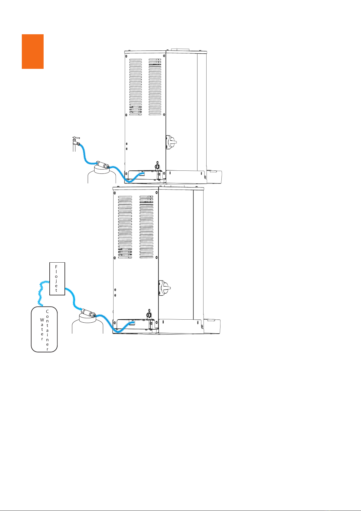
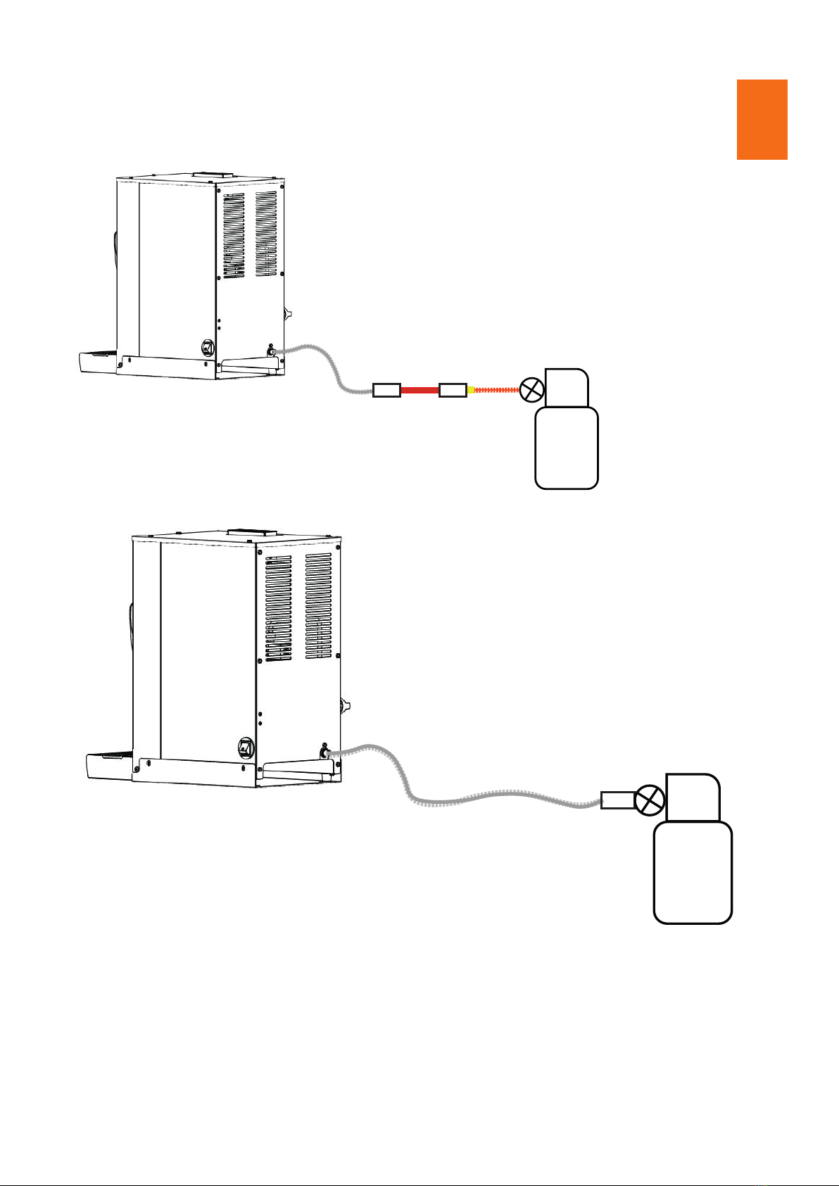
Static LPG installation
Connect the approved 2.75kPa xed pressure regulator to the 1/2” gas inlet tting at
the rear of the appliance, ensuring it is tight, then connect 1/2” gas hose to the gas
xed gas regulator also ensuring it is tight. Attach an isolation valve to the other end of
the gas hose which is then connected to a suitable ULPG bottle.
LPG Mobile installation
Connect the approved 2.75kPa xed pressure regulator to the 1/2” gas inlet tting at
the rear of the appliance, ensuring it is tight, then connect 1/2” gas hose to the gas
xed gas regulator also ensuring it is tight.
Attach an isolation valve to the other end of the gas hose. Attach the isolation valve to
8mm ridged mounted copper tube at a length suitable for installation, ensure that the
pipework is in a location where is CAN NOT be easily damaged.
The copper tube is connected to a bulkhead tting that has a Fulham nozzle protruding,
x the required high-pressure hose to the Fulham nozzle with a jubilee clip ensuring it
securely xed.

The other end on the high-pressure hose is connected to an appropriate ULPG bottle.
NOTE – All gas supply hoses or tubes shall comply with the national requirements in
force and shall be examined periodically and replaced if necessary.
NOTE – It is recommended that a gas sealant is used on all joints.
NOTE – Gas installations should only be carried out by a qualied engineer and in
accordance to AS 5061.
NOTE – Installer must test the operation on the appilance after installation by following
the ON/OFF & Operation section of this manual.
Gas Cylinders
Below is a list of gas bottle types and sizes that can be use with the appliance.
Gas Type Bottle Size Position in accordance with;
LPG 6kg - 495mm(h) x 256mm(d) EN1717(UK/EU) or AS 5601(AUS/NZ)
LPG 13kg - 580mm(h) x 315mm(d) EN1717(UK/EU) or AS 5601(AUS/NZ)
LPG 19kg - 810mm(h) x 375mm(d) EN1717(UK/EU) or AS 5601(AUS/NZ)
BUTANE 4.5kg - 340mm(h) x 240mm(d) EN1717(UK/EU) or AS 5601(AUS/NZ)
BUTANE 7kg - 495mm(h) x 256mm(d) EN1717(UK/EU) or AS 5601(AUS/NZ)
BUTANE 15kg - 580mm(h) x 318mm(d) EN1717(UK/EU) or AS 5601(AUS/NZ)

Securing the appliance in place.
To ensure the appliance doesn’t move when installed on a mobile unit it should be
xed to the mounting plate.
Once the appliance has been connected and functional tests have been completed it
can be secured to the mounting plate .
Align the xings on the side of the appliance with xing holes on the sides of the
mounting plate. Once these are aligned, secure the appliance to the mounting plate
using 4 M5x12mm Hex Flange Bolts (supplied with the unit).
Connecting the power supply
Take the main power cord and plug it directly into a plug socket or inverter.
Ensure that the appliance is within 1m of the power supply.
NOTE: Installation engineer must test the appliance after installation to ensure
everything is working correctly. The appliance is not to be passed o until functional
tests have been carried out.

Turning on/o & Operation
WARNING: Before turning on the appliance ensure electric, water and gas supplies
are turned on and kept on during operation.
1) Before igniting the Water Boiler, switch on
using the mains on/o switch located on the
right side of the unit.
Mains on/o switch
2) From the OFF position depress the gas valve knob and rotate to the rst position piezo
holding for 20 seconds, this is to ensure gas is purged through the system. Release the
knob and return back to o position
5
43
1
2
Symbol Identication
1 - O
2 - Piezo Ingnite
3 - Pilot Position
4 - Low Flame
5 - High Flame

3) From the OFF position depress the gas valve knob and rotate to piezo ignite position.
The valve knob should click twice and come to a stop as the piezo sparks to light the pilot.
Still holding in the valve knob, check through the pilot viewing hole that the pilot light is lit. If
the pilot light is not lit repeat this step until it is.
Note: On initial setup or after a prolonged period of not being used, repeating step 3 is
common.
Once the pilot light is lit, continue to hold knob in for 20 seconds to allow the thermocouple
to heat up, then slowly release the knob, the pilot should stay lit and the valve knob should
now be positioned at the pilot ame setting.
Pilot viewing hole
4) Depress the gas knob and rotate anti-clockwise until the valve is set to
the high ame position, then release the knob. The burner is now set to the
high ame and will start heating.
5) Whilst the water boiler is being lit the water tank will ll automatically with cold water which
is indicated by the blue LED positioned on the front of the machine. Once the water level has
reached the required amount the LED will switch o.
6) The red LED indicates when the appliance is heating. Once the set temperature of 92°C is
reached the LED will switch o.
Once the boiler reaches temperature it is ready to use.
Heating LED
Filling LED

Turning o
Hazardous operation
1) Depress the gas valve knob and return to the OFF position this will shut o the burner and
extinguish pilot light, to check use viewing aperture.
2) Turn o mains on/o switch
3) Isolate the water, gas and electricity supply
The appliance is now o and safe.
It should not be possible to operate the appliance in hazardous conditions; however if when
lighting the appliance an excessive amount of gas has been purged then it is advised to stop
the ignition sequence and let any build up of purged gas to disperse, not doing so could lead
to combustion of the gas.
Only ignite the appliance as stated in the instructions. DO NOT use other methods to light the
appliance. If piezo ignition fails then it is recommended a service is carried out.
If the burner is extinguished whilst the appliance is in normal use the gas valve will shut o
automatically. If this fails and gas continues to be expelled manually, close the gas valve on
the side of the appliance, turn o the mains power and isolate the appliance until any excess
gas has dispersed. if the burner contines to extinguish it is recommened the appliance is
servied by a qualied engineer.
In case of malfunction, immediately cease usage and disconnect from electricity and close
of gas supply. Do not try to solve the problem, contact your supplier or technical service
engineer.

Operating the water boiler
To operate the appliance rst ensure appliance is to temperature.
1) Place a cup/mug or tea pot on the drip tray central to the water valve, ensure
the drip tray grid is in place before use. DO NOT hold liquid vessel whist lling to
reduce the risk of scalding.
2) Pull black water valve lever forward to start ow of hot water, if required the
lever can be pulled down fully and locked into place.
3) Once required amount of hot water is dispensed then return water lever back to
the closed position to stop ow of water.
Ensure drip tray is emptied periodically to prevent overow and make sure drip
tray is tted back into place before use. Not doing so could lead to spillage of
water from overow and condensation outlet onto counter tops.
WARNING: Water from this appliance is hot and can scald, care must be taken
with using it.

AB
CD
Cleaning
WARNING: Do not use scouring pads or
bleach based cleaners on this appliance,
doing so will damage the stainless steel
nish.
WARNING: Do not immerse this
appliance in water to clean.
Cleaning should be carried at least once
daily.
1. Wipe the outer case with soft damp
cloth.
2. Remove and empty the drip tray.
Wash the drip tray and drip tray grid in
warm soapy water. Replace the drip tray
and grid once clean and fully dry.

Maintenance
The recommended service interval is 12 months.
WARNING: Maintenance other than regular cleaning should only be performed by
trained personnel/service engineers. Failure to use trained engineers may cause
damage, injury and invalidate the warranty.
WARNING: Ensure the appliance has been fully isolated from the water, gas and
mains power supply before removing any body panels.
WARNING: Allow the appliance to cool for a minimum of 30 minutes before carrying
out any maintenance.
WARNING: Fully isolate the gas supply at the gas bottle before carrying out any
maintenance.
WARNING: Service to the gas components can only be carried out by qualied
personnel who are Gas Safe registered with a COMCAT 2 certicate or relevent
regional qualications
To drain the water boiler pull the drain tube from underneath and put the end into a
waste container. Once the drain tube is in position, remove the drain plug from the
tube and allow the water to drain from the tank. Once the tank is empty, ret the
drain plug and place the drain tube back underneath the water boiler.
Recommended Spare Parts List
Description Part Number
Valve Handle WB222COM
Valve Handle WB306
Pilot Assy ODS LPG WB304-LPG-COM
Pilot Assy ODS Natural Gas WB304-NG-COM
Injector Jet 0.85mm (LPG) FCL301-2 (used with WB304-LPG-COM only)
Injector Jet 1.35mm (NG) FCL301-1-NG (used with WB304-NG-COM only)
Gas Valve Solenoid FC171-GAS-COM
Control Box WB172
High Temperature Stat HEA166
Steam Overheat Stat WB166

Wiring Diagram

Warranty
Terms and Conditions
1. Fracino machines are guaranteed to be free from defects in material and
workmanship during manufacture for a period of 12 months from the initial
installation.
2. Liability under the warranty is limited at the option of the manufacturer to the
replacement or repair, free of charge, of such parts shall be acknowledged
after the manufacturer’s inspection to be defective in material or workmanship,
provided that any such claims under this warranty are notied to the manufacturer
without delay. All parts recognised as defective shall become the property of the
manufacturer.
3. Except in so far as injury, damage or loss caused by the negligence of the
manufacturer or its employees insofar as exclusion is not prohibited or negated
by law this warranty is in substitution for any express or implied guarantee,
representation warranty or condition and the manufacturer shall not be liable
for any injury, damage or loss directly or indirectly attributed to any or done in
connection herewith.
4. The unexpired part of this warranty may be transferred to another owner
providing the machine has been serviced and maintained by the manufacturer or
manufacturer’s authorised service agent as prescribed and remains in the same
location.
5. The warranty shall cease immediately if:
A. The machine is modied or added to in any way not previously agreed with the
manufacturer in writing including tting non genuine parts.
B. The instructions contained in Operator’s Manual are not complied with.
C. The machine is installed, serviced, relocated or maintained by anybody other
than the manufacturer or manufacturer’s authorised service agent.
6. The warranty does not cover items that require replacement in the course of
maintenance or as a result of fair wear and tear, nor does it cover lime scale
related faults.
7. Kindly observe the following in your best interests:
A. We recommend using only Fracino original parts explicitly approved by the
manufacturer. These parts have been selected for their reliability and suitability
for Fracino machines.
B. We are unable to make assessments for other product parts and therefore
cannot be held responsible for them, even in individual cases an ocial
approval or authorisation by governmental or approval agencies exist.
C. Fracino original parts as approved can be obtained from the factory.
Comprehensive assistance and advice on maintaining your machine at its
optimum level can be obtained from Fracino, or visit our website -
www.fracino.com
Table of contents
Other Fracino Coffee Maker manuals

Fracino
Fracino Roastilino User manual

Fracino
Fracino Vesuvius User manual

Fracino
Fracino Heavenly User manual

Fracino
Fracino PID 2 User manual

Fracino
Fracino ATTIMO User manual

Fracino
Fracino GE948 User manual

Fracino
Fracino Heavenly User manual

Fracino
Fracino Cybercino User manual

Fracino
Fracino Bambino User manual