FRANCO RoofCooler Instruction manual

INSTRUCTION MANUAL
FOR USE AND MAINTENANCE
ROOF COOLER
EVAPORATIVE COOLER
E N G L I S H
Before installing or running the unit,
it is obligatory to carefully read and consult this manual.
Manual version: 06-011/2020 Franco srl –Via Nazionale, 80 12010 Cervasca (CN)
INDEX

FRANCO srl Manual of use and maintenance ROOF COOLER
2
INDEX ......................................................................................................................................1
1 - INTRODUCTION.................................................................................................................3
1.1 General warnings............................................................................................................3
1.2 Instructions for proper disposal of the product................................................................3
1.3 Covenants used throughout this manual ........................................................................4
1.4 Conservation of the instruction manual...........................................................................4
1.5 Recipients.......................................................................................................................5
1.6 Glossary and pictographs...............................................................................................5
1.7 Applicazioni.....................................................................................................................9
1.8 Versions..........................................................................................................................9
1.9 Identification and data label of the unit ...........................................................................9
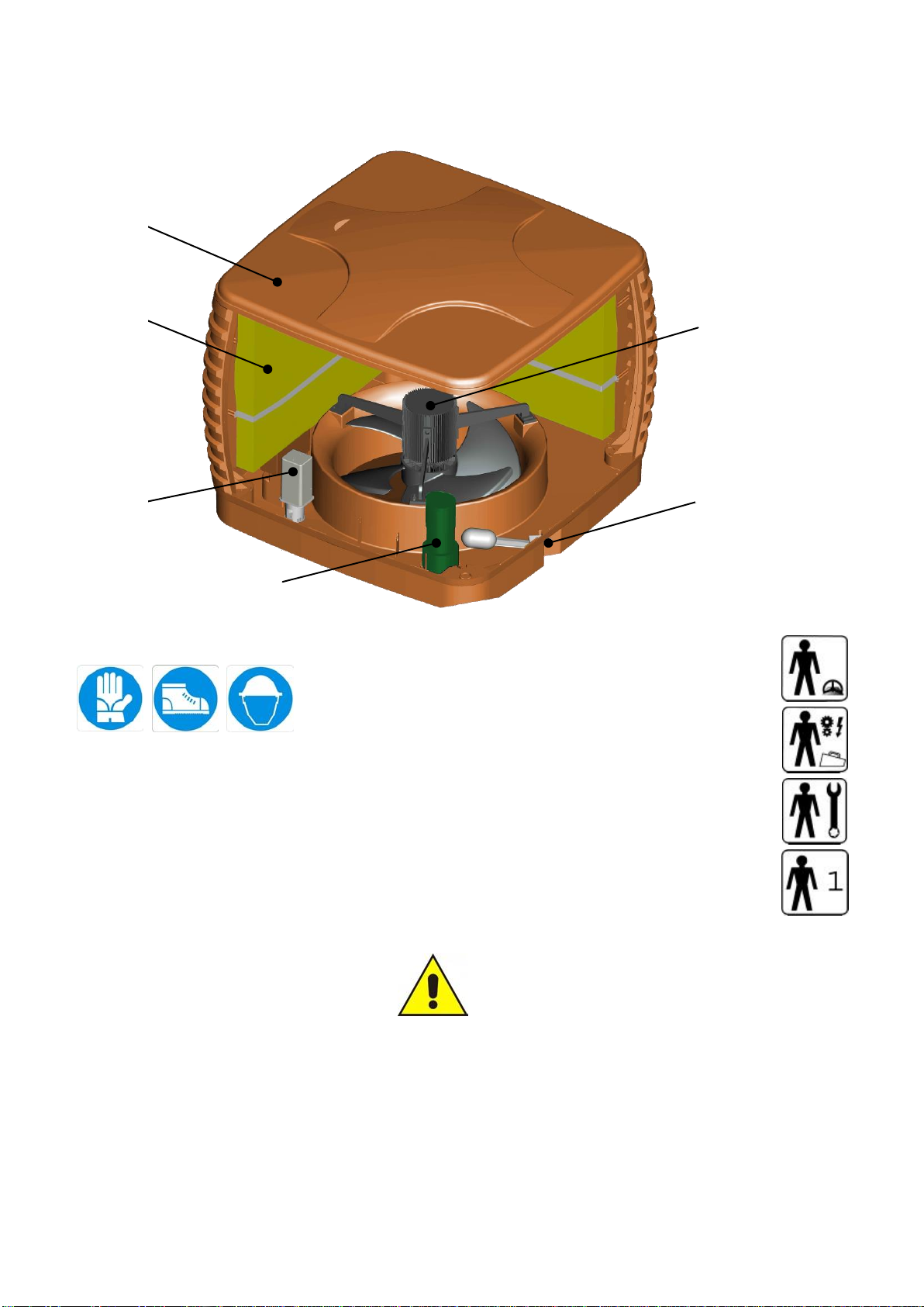
1.10 Description of the parts...............................................................................................10
1.11 Transport and handling...............................................................................................10
1.12 Warranty.....................................................................................................................11
1.13 Statements..................................................................................................................11
1.14 Declaration of conformity............................................................................................12
1.15 Declaration of incorporation........................................................................................ 13
2 - INSTALLATION................................................................................................................ 14
2.1 Before installing............................................................................................................ 14
2.2 Positioning....................................................................................................................14
2.3 Electrical connection.....................................................................................................15
2.4 Hydraulic connection .................................................................................................... 15
3 - OPERATION..................................................................................................................... 16
3.1 Getting started..............................................................................................................16
3.2 First start.......................................................................................................................16
3.3 Starting ......................................................................................................................... 16
3.4 Optimum conditions of usage .......................................................................................17
3.5 Water Drainage (bleed-off) ...........................................................................................17
4 - MAINTENANCE................................................................................................................ 18
4.1 Cleaning the panels......................................................................................................18
4.2 Cleaning the tank..........................................................................................................18
4.3 Replacing the pump...................................................................................................... 18
4.4 Replacing the float........................................................................................................18
4.5 Replacing the exhaust ..................................................................................................18
4.6 Replacing the panels ....................................................................................................18
5 - TECHNICAL SPECIFICATIONS ...................................................................................... 19
5.1 Technical data ..............................................................................................................19
5.2 Wiring............................................................................................................................20
5.3 Spare parts...................................................................................................................21
6 - PROBLEMS AND SOLUTIONS ....................................................................................... 23

FRANCO srl Manual of use and maintenance ROOF COOLER
3
1 - INTRODUCTION
1.1 General warnings
This device must be used only for the functions for which it was intended "Adiabatic Cooler –Humidifier”.
Any other use is to be considered improper and dangerous. Franco S.r.l. cannot be held liable for any damages
caused by improper, incorrect or unreasonable use, or if the device is used in systems that do not comply with
safety regulations.
- Check the integrity of the device at the opening of the package, paying particular attention to the presence of
damages or deformations of the plastic parts that can lead to breakage and / or malfunction during use. In such
cases do not connect the machine to the mains. Carry out these checks before each use.
- Before connecting the unit, make sure that the data shown on the device’s plate matches that of your electricity
distribution network. The data label is located on the side of the device (par.1.9).
- Respect the safety standards set for the electrical equipment and in particular:
oFollow the installation and operation instructions concerning the use of the equipment.
oDo not place objects on the humidifier.
oAvoid children from using the device, and / or unable subjects without proper supervision.
oDo not touch the humidifier during operation or until the complete stop of the disk.
oNever place water or any other liquids into the device. In the scenario of the device becoming wet,
immediately turn off the electricity by lowering the switch on the electrical panel of your system and
disconnect the power before touching the device.
oDo not insert objects inside the tank as the device may be damaged irreparably.
oDo not use accessories, spare parts and / or components that are not provided or supplied by the
manufacturer.
oAvoid touching the appliance with wet and / or humid hands.
oDo not pull the power cord nor expose it to risk of severing.
oDo not expose the unit to weather (rain, sun, etc...).
oIn case of failure or malfunction, switch off immediately and disconnect the power. Do not try to open or
tamper the device: contact the technical service offered by Franco srl.
oDo not try to fill and / or empty the tank during operation.
1.2 Instructions for proper disposal of the product
Under the European Directive 2002/96/EC.
At the end of its useful life the product must not be disposed of as waste.
The device can be taken to special recycling centers provided by local authorities, or at retailers that provide this
service. Disposing the product in separate parts avoids possible negative consequence to the environment and
to human health, which would both be the result of an inappropriate disposal, and allows the retrieval of
materials so that significant savings in energy and resources would be reached. As a reminder of the obligation
to dispose electrical equipment separately, the product is marked with the crossed mobile waste container.
Fig. 1.1

FRANCO srl Manual of use and maintenance ROOF COOLER
4
1.3 Covenants used throughout this manual
The Manual is divided into autonomous chapters, each of which is addressed to a specific operator’s figure
(installer, operator and maintainer), for which the skills needed to operate the machine safely have been defined.
The sequence of chapters follows the temporal logic life of the machine.
To facilitate the immediate comprehension of the text, throughout the manual are used terms, abbreviations and
pictograms, whose meaning is shown below.
The Instruction Manual consists of a cover, an index and a series of chapters (sections).
The home page lists the identification data of the machine and model, the revision of the manual instructions,
and finally, a picture of the machine described, drawn in order to facilitate the reader in identifying the machine
and its use.
ABBREVIAZIONI
Ch. = Chapter
Par. = Paragraph
P. = Page
Fig. = Figure
Tab. = Table
UNITS OF MEASURE
The units of measure used in this manual are those provided by the International System (SI).
1.4 Conservation of the instruction manual
The instruction manual must be carefully stored and must follow and match the device in all the cases of change
of ownership incurred during the life span of the machine itself.
The conservation must be done by handling the manual with care, with clean hands and on clean surfaces. Parts
must not be removed, torn or arbitrarily modified.
The manual must be stored in a secure environment, protected from moisture and heat, and near the referring
device. The manufacturer, if requested by the User, may provide additional copies of the instruction manual of
the machine.
The User can request additional copies of the manual by contacting customer@francosrl.com
METHODOLOGY FOR UPDATING THE MANUAL
The Manufacturer reserves the right to modify the design or specifications of the machine as part of its policy of
improving and enabling them to comply with the statutory or other requirements or standards applicable in any
territory in which goods are sold, without notifying the Customer and without updating the manuals given to the
user. Moreover, in case of changes (previously agreed between the Customer and the manufacturer) to the
machine installed, which signifies the modification of one or more chapters of the Handbook of Instructions, the
manufacturer will be responsible for sending the modified chapters affected by the structural change (including
the new model of revision) to the User.
The User is responsible, following the directions accompanying the updated documentation, for replacing all the
copies owned, the old chapters with the new chapters, the home page, and the index with the copy updated to
the new revision level.
The manufacturer shall be responsible for the descriptions included in this manual; in case of an inconsistency
being detected in a translated version of the manual (English version), the reader must refer back to the original
Italian version of the handbook and, eventually, contact the sales department, who will make necessary
changes.

FRANCO srl Manual of use and maintenance ROOF COOLER
5
1.5 Recipients
The manual is addressed to: the installer, the operator, and the qualified personnel entitled to the maintenance
of the device.
EXPOSED PERSON:
refers to any person exposed, wholly or partially, to a danger zone;
OPERATOR:
refers to those persons responsible for installing, operating, regulating,
clearing, repairing and moving the machine, and also performing the
maintenance of the device;
QUALIFIED PERSONNEL
QUALIFIED OPERATOR:
refers to the persons who have completed courses of specialization and
training, and that have acquired experience in: installing, starting,
operating, maintaining, repairing and transporting the device, or similar
ones.
The machine is intended for industrial use (professional and not widespread) for which qualified operators are
needed, in particular, workers that:
Have reached the age of majority;
Are physically and mentally appropriate to perform works that include technical difficulties;
Have been properly educated on the use and maintenance of the machinery;
Have been considered suitable to undertake the assigned job by their employer;
Can understand and interpret the operator’s manual and the safety requirements;
Know the emergency procedures and their implementation;
Posses the ability to operate the specific type of equipment;
Are familiar with the specific applicable rules;
Have understood the operating procedures defined by the manufacturer of the machine.
1.6 Glossary and pictographs
In this section we list the non common terms included in the manual. The following also explains the
abbreviations used and the meaning of the pictograms in relation to the qualification of the operator and the state
of the machine; their use can provide quick and unique information, necessary for the proper use of the machine
under safety conditions.
GLOSSARY (Att. I p. 1.1.1 Dir. 2006/42/CE)
HAZARD
A potential source of injury or damage to personal health;
DANGER ZONE
All areas within and/or around the machinery in which the
presence of a person constitutes a risk to the health and safety of
himself/herself;
EXPOSED PERSON
Any person that finds himself/herself entirely or partially in a
hazardous area;
OPERATOR
The person responsible for installing, operating, regulating,
clearing, repairing and moving the machine, and also performing
the maintenance of the machinery;
RISK
The combination of probability and severity of an injury or harm to
health that can arise in a hazardous situation;
GUARD
The part of the machinery used specifically to provide protection by
means of a physical barrier;
PROTECTION DEVICE
The device (other than a shelter) that reduces (alone or in
conjunction with a shelter) the risk of an operation;
INTENDED USE
Use of the machinery according to the information provided in the
instruction manual;
REASONABLY FORESEEABLE
MISURE
Use of the machinery in an indifferent manner from that stated in
the instruction manual, which may result from a foreseeable
human behavior.

FRANCO srl Manual of use and maintenance ROOF COOLER
6
OTHER DEFINITIONS:
HUMAN-MACHINE INTERACTION: Any situation in which an operator interacts with the machine in any of
the operational phases at any time of the life of the machine itself;
OPERATOR’S QUALIFICATION: Minimum level of competence that an operator must have in order to
perform the described operation;
NUMBER OF OPERATORS: The appropriate number of operators needed to optimally perform the
described operation, it is derived from an accurate analysis made by the
manufacture, and for which the use of a different number of operators
may prevent the occurrence of the expected result or endanger the
safety of the personnel involved;
STATE OF THE MACHINE: The state of the machine includes the operating mode, for example:
running in automatic mode, maintained action control (jog), shutdown,
etc… the safety conditions on the machine such as included protectors,
excluded protectors, emergency shutdown, isolation from energy
sources, etc…
RESIDUAL RISK: Risks that remain, despite of the protective measures incorporated in the
design of the machine, the complementary protections, and the
additional protective measures.
SAFETY COMPONENT: Component:
- designed to fulfill a safety function;
- the failure and/or malfunctioning of which endangers the safety of
persons (such as a lifter; a fixed, moving or adjustable protector; an
electrical, electronic, optical, pneumatic or hydraulic device that interlock
a protector; etc…).

FRANCO srl Manual of use and maintenance ROOF COOLER
7
PICTOGRAPHS CONCERNING THE OPERATOR’S QUALIFICATION
Symbol
Description
Generic laborer: operator lacking of specific competences, capable of performing only simple tasks
under the control of qualified technicians.
Lifting and handling vehicles driver: operator qualified for the use of vehicles used in lifting and
handling materials and machines (carefully following the manufacturer’s instructions), in accordance
with the user’s country’s laws.
Mechanic maintainer: qualified technician, able to operate the machine under normal conditions, to
run it with the maintained action control (JOG) with disabled protections, and to intervene on the
mechanical parts in order to make the necessary adjustments, maintenances and repairs. Typically
this operator is not qualified to work on electrical systems while the device is connected to the
mains.
Electrical maintainer: qualified technician, able to operate the machine under normal conditions, to
run it with the maintained action control (JOG) with disabled protections, and enabled to any kind of
operation of electrical adjustment, maintenance and repair. This operator is qualified to work on
electrical systems while the device is connected to the mains.
Manufacturer’s technician: qualified technician offered by the manufacturer to carry out complex or
particular operations or, in any other case agreed with the user. The skills are, as contingently
appropriated, mechanical and/or electrical and/or electronic and/or concerning software.
PICTOGRAPHS CONCERNING THE STATE OF THE DEVICE
The pictographs contained in a square/rectangle provide information.
Symbol
State of the device
Device OFF: with electric and pneumatic power disconnected.
Machine in motion: with automatic function, movable protections closed and relative interlocking
devices activated, and fixed protections closed.
Device ON: in standby and ready to start by functional consent activation (eg. switchboard
consent), movable protections closed with relative safety device included, and fixed protections
closed.

FRANCO srl Manual of use and maintenance ROOF COOLER
8
PICTOGRAPHS CONCERNING SAFETY
The pictograms contained in a triangle indicate DANGER.
The pictograms contained in a circle impose PROHIBITION / OBLIGATION.
Pictograph
Denomination
Hazardous voltage.
Entanglement.
Dragging.
General danger.
Do not remove safety devices.
Prohibition of cleaning, oiling, greasing, repairing or adjusting by hand when the device is in motion.
Duty to remove power before starting works or repairs.
Protective gloves required.
Safety footwear required.
Safety helmet required.

FRANCO srl Manual of use and maintenance ROOF COOLER
9
1.7 Applicazioni
The machine is installed in places where it is necessary to cool large spaces, i.e. warehouses, workshops,
animal enclosures, farms, etc…
The materials used in building the machine ensure reliability and durability in time.
The humidifier parts are made in ABS, the screws are stainless steel made.
The use of materials that do not suffer from the corrosive action of water and acids makes the ROOF COOLER a
machine capable of working in almost all the environments.
The required water pressure is that of the water supply (between 2 and 6 atm).
This device must be used only for the functions for which it
was intended and designed:
Adiabatic (evaporative) Cooler.
Any other use is to be considered improper and dangerous.
1.8 Versions
The adiabatic cooler RoofCooler is available in the following versions:
2903000 Version with ventilator 400V 50Hz three phase
2903100 Version without ventilator
WARNING!
Version cod.2903100 must be installed on
duct with a maximum air flow of 15.000m³/h !
1.9 Identification and data label of the unit
Each machine is identified by the CE plate on which, indelibly set, is reference data of the device itself.
In any communication, either with the manufacturer or with the customer service, always cite these references.
Fig.1.2
The label plate positioning may vary from one device to another.

FRANCO srl Manual of use and maintenance ROOF COOLER
10
1.10 Description of the parts
Fig.1.3
1.11 Transport and handling
The machine has been properly packaged before being put into strong carton boxes.
Prevent damages to the components of the device by taking care when opening the package.
Verify the integrity of the machine by controlling that there are no visible damaged parts.
Do not dispose the packaging elements in the environment; they must be placed in proper collection
points.
The RoofCooler can be lifted by using the proper brackets.
WARNING!
Before handling the device:
a. stop the machine,
b. disconnect the electricity supply,
c. interrupt the water supply.
To lift the machine, use a suitable lifting device (consult the weights table).
Lift the machine slowly, being careful not to drop it and move the straps depending on the center of mass.
Machine
body
Recirculation pump
Evaporative
panel
Drainage
device
Float valve ½”
Ventilator

FRANCO srl Manual of use and maintenance ROOF COOLER
11
1.12 Warranty
This device is guaranteed for 12 months from the date of manufacture for all failures attributed to a proven
manufacturing or material defect.
All the parts damaged by transport, improper maintenance, negligence, inability to use, improper use, tampering
by unauthorized personnel and by any other cause not dependent from the company Franco S.r.l. from
Cervasca (CN), Italy. During the warranty period, the company Frano S.r.l. commits itself to replace or repair free
of charge those parts which result faulty from the origin.
The intervention must be made at Franco S.r.l. with transport charged to the user.
1.13 Statements
The machine is built in accordance with the EC directives that are relevant and applicable at the time of the
market entry of the machine itself.
The machine is not among those mentioned in the Att. IV of the Directive 2006/42/CE.
Cod. 2903100 version is sold as PARTLY COMPLETE MACHINE it is necessary to provide it a ventilator or use
it in combination with a dynamic ventilation system with a maximum airflow of 15.000m³/h.
The partly complete machine is built in accordance with the EC directives that are relevant and applicable at the
time of the market entry of the machine itself.
The partly complete machine is not among those mentioned in the Att. IV of the Directive 2006/42/CE.

FRANCO srl Manual of use and maintenance ROOF COOLER
12
1.14 Declaration of conformity
(Att. IIa DIR. 2006/42/CE)
THE MANUFACTURER
FRANCO S.r.l.
Company
Via Nazionale, 80 12010 CN
Address Postal code Province
Cervasca Italy
City Country
DECLARES THAT THE MACHINE
Cooler RoofCooler
Description Model
2903000 / 2903100 / 2903010 / 2903011 / 2903020 / 293021 2019
Series/Registration number Year of construction.
Roof Cooler - adiabatic (evaporative cooler)
Commercial denomination
Cooling of environments
Intended use
Meets the following essential requirements:
RESS from 1.1 to 1.7
Complies with the EU directives:
Directive 2006/42/CE - Directive 2006/95/CE - Directive 2004/108/CE
Referring to harmonized norms: EN 120100-1; EN 12100-2;EN 60204-1
AND AUTHORIZES
Marco Fantino
Nominative
Via Nazionale 80 12010 CN
Address Postal code Province
Cervasca Italia
City Country
TO COMPILE THE TECHNICAL FILE ON HIS BEHALF
Place and date of the document
The manufacturer
Cervasca, 10/05/2019
Firma
Function
Administrator
D.C.: DC N-001/290001

FRANCO srl Manual of use and maintenance ROOF COOLER
13
1.15 Declaration of incorporation
(Att. IIb DIR. 2006/42/CE)
THE MANUFACTURER
FRANCO S.r.l.
Company
Via Nazionale, 80 12010 CN
Address Postal code Province
Cervasca Italy
City Country
DECLARES THAT THE PARTLY COMPLETE MACHINE
Cooler RoofCooler
Description Model
2903000 / 2903100 / 2903010 / 2903011 / 2903020 / 293021 2019
Series/Registration number Year of construction.
RoofCooler
Commercial denomination
Cooling in combination of dynamic ventilation systems (maximum air flow 15.000 m³/h)
Intended use
Meets the following essential requirements:
RESS from 1.1 to 1.7
Complies with the EU directives:
Directive 2006/42/CE - Directive 2006/95/CE - Directive 2004/108/CE
The relevant technical documentation has been compiled in accordance with the annex VII B of
machinery directive. All relevant information about the partly completed machinery will be provided on a
reasoned request by the appropriate national authority to its authorized representative.
IT IS NOT ALLOWED
to put our products into operation until the machine into it is to be incorporated or of which it is to be a
part has been found and declared in conformity with the provisions of legislation, i.e. as a whole,
including the product subject of this declaration.
AND AUTHORIZES
Marco Fantino
Nominative
Via Nazionale 80 12010 CN
Address Postal code Province
Cervasca Italia
City Country
TO COMPILE THE TECHNICAL FILE ON HIS BEHALF
Place and date of the document
The manufacturer
Cervasca, 10/05/2019
Firma
Function Administrator
D.I.: DI N-001/180001

FRANCO srl Manual of use and maintenance ROOF COOLER
14
2 - INSTALLATION
2.1 Before installing
In order to start the Roof Cooler, the following conditions are required:
• connection to the electric power supply with voltage and frequency suitable for
the machine and with grounding and safety devices;
• connection to water supply (pressure required: between 2 and 6 atm);
• a dynamic ventilation system (air flow >1 m/s)
• where expected: water drain connection.
The installation must meet the safety requirements
provided by local regulation in force.
Make sure that all the connections necessary to operate the equipment have been properly prepared.
2.2 Positioning
The positioning of the UCP-fly must be done by maintaining the minimum recommended distance that
allows the correct operation of the machine and to perform maintenance when needed.
Choose, depending on the type on installation adopted, the most suitable position for the
cooling of the environment.
The installment of the machine must meet the safety distance in
accordance with the norm UNI EN ISO 13857/2008.
It is necessary to install a proper air duct or air distributor in order to avoid any contact
with the machine ventilator.
Installation example - roof bracket.
Please contact our technical dept. for other installation example.
Square profile 50x50

FRANCO srl Manual of use and maintenance ROOF COOLER
15
2.3 Electrical connection
The installation involves the use of a humidistat or a thermostat ON/OFF controlling the power
of the machine; it is still possible to use, alternatively, a switch ON/OFF, in this case the start
and stop of the machine must be done manually.
The choice, however, does not affect the installation procedure described below.
Electrical connections must be undertaken by specialized, experienced and trained
technicians, in accordance with the current legislation.
Ensure that the electricity supply specifications correspond to those indicated in the
in this manual.
It is obligatory that the device is grounded using an efficient ground line.
The installation must foresee a device enabled to disconnect the machine from the electric supply, furthermore,
a safety fuse (delayed motor starting type) or an adequate motor protection switch must be installed.
It is suggested to install a timed switch for the drainage of the tank (Bleed-Off function), in order to maintain the
machine in proper working conditions.
2.4 Hydraulic connection
The installation of the Cooling device foresee the connection to the piping lines of water supply and drainage at
the proper points (Fig. 1.3).
A 3/8”M connection is disposed for drainage; a 1/2"M fit is predisposed for water supply (or a 3/8”
fast connection, “rilsan” hard type pipe).
The pipes that must be used are of type hard “rilsan” for drainage, while, for the supply, a 1/2” fit is
predisposed.

FRANCO srl Manual of use and maintenance ROOF COOLER
16
3 - OPERATION
3.1 Getting started
Before operating the humidifier, verify that:
1. All connections, both electrical and hydraulic, are made according to the instructions contained in this
manual;
2. The humidifier is free and clean;
3. The water supply tap is open.
3.2 First start
- Check the correct air flow direction (Fig. 3.1);
- Make sure all wires are regularly placed and not caught or pulled by any object;
- Ensure that the water connections are correct;
- Open the water supply tap and make sure that there are no leaks along the load circuit;
- Check floating valve operation and the level of the water.
Fig. 3.1
The pump must not operate without water.
The temperature of the liquid used must not exceed 35°C.
3.3 Starting
The machine starts automatically when the electrical power is switched on
The pump circulates the water bringing it to the water distributors above the panels made of cellulose.

FRANCO srl Manual of use and maintenance ROOF COOLER
17
3.4 Optimum conditions of usage
WATER
Use water with a recommended PH between 6 and 8; never use a lower or higher PH level in order to avoid
damages to the panel.
It is strongly recommended to use water with a maximum CaCO3 of 250ppm.
To avoid that the degree of salinity exceeds the acceptable limits it is suggested to perform purging cycles on the
recirculating water circuit.
WARNING! Do not use hot water; use only water at room temperature!
INCRUSTATIONS
Encrustations are mainly caused by the formation of calcium carbonate and we suggest the following in order to
prevent them:
- Frequently clean the water tank
- Make frequent water discharge cycles
ALGAE PREVENTION
Perform drying cycles of the panels.
In the working season is enough a drying cycle once a day.
To avoid the formation of algae panel should dry quickly, it is suggested to turn off the recirculation pumps
before turning off the fan; and to turn on the fan the fans before operating the recirculation pumps.
3.5 Water Drainage (bleed-off)
The machine is equipped with a drain servo for emptying the tank.
During operation of the cooler, the water evaporates and the concentration of minerals in the water recirculation
increases.
To avoid this phenomenon, it is appropriate to timing the drainage of the tank.
It is recommended to activate the drainage system for a period of 10 seconds every half hour.

FRANCO srl Manual of use and maintenance ROOF COOLER
18
4 - MAINTENANCE
Before undertaking any maintenance,
disconnect the device from the electricity and water supply!
Periodically check that the amount of water reaching the panels is correct, in order to water them correctly.
Keep clean the grids, the tank and the internal components, and prevent the accumulation of dirt on the lid.
4.1 Cleaning the panels
Keep the panels clean to avoid the formation of calcareous deposits or accumulation of dirt, which could cause
bad performances in cooling.
Do not use solvents.
4.2 Cleaning the tank
Periodically clean the water tank.
Clean the interior of the tank with a cloth or a sponge, rubbing gently on the walls. Do not use solvents.
It is necessary to periodically check the functioning and the cleanliness of the pump and the float.
Every 3-4 months clean the internal parts of the pump with warm water.
4.3 Replacing the pump
Electrically disconnect the pump and remove the water hose by loosening the hose clamp.
Hold the lever that allows unlocking (marked with a padlock) and turn the pump to release it from its seat.
Repeat the sequence backward, making sure that the lock lever clicks once in position.
4.4 Replacing the float
Disconnect the water supply and remove any union connections from ½ " attack of the machine.
Unscrew the ring nut and remove the body of the float.
Place the new float and repeat the sequence in the opposite direction, so that the water level inside the tank
covers the pump impeller completely.
4.5 Replacing the exhaust
Drain the water in the tank and disconnect the exhaust system electrically.
Disconnect the exhaust pipe and remove the exhaust system.
Place the new drain system and repeat the sequence in the opposite direction, making sure the seal is
positioned on the bottom of the tank, removing any dirt or impurities.
4.6 Replacing the panels
Unscrew the 4 screws on the racks door-side panel and gently unhook from their position, pulling it up.
Remove the screws from the locking bands to replace the evaporative pad.
In order to improve the distribution of water in the upper part of the panels there is a distributor in cellulose that
has a different texture from the rest of the panel.
Repeat the sequence backward, making sure the area of the distribution pad is positioned upwards.

FRANCO srl Manual of use and maintenance ROOF COOLER
19
5 - TECHNICAL SPECIFICATIONS
5.1 Technical data
2903000
2903100
Maximum air flow
m³/h
15.000
15.000
Weight (without water)
kg
80
80
Tank capacity
l
45
45
air flow outlet
mm
square: 660x660 - round: Ø610
Loss of pressure
Pa
- -
100
VENTILATOR
Power supply
400V 50Hz
- -
Power
W
1500
- -
Absorbed current
A
3,6
- -
PUMP
Power supply
230V 50Hz
230V 50Hz
Power
W
30
30
Absorbed current
A
0,15
0,15
DRAIN
Power supply
230V 50Hz
230V 50Hz
Power
W
20
20
Absorbed current
A
0,1
0,1

FRANCO srl Manual of use and maintenance ROOF COOLER
20
5.2 Wiring
All the wires used must be suitable to carry the current intensity (A) of the motor (par. 5.1).
The terminal’s screws must be accurately tightened.
Make sure that the electricity supply characteristics are exactly as shown in the table (par. 5.1).
Install a differential magnetic switch upstream of the device.
Protect with a suitable motor overload protection (par 5.1).
Make sure all connections are stuck on the box, the box cover is secured and that the screws
are tightened to ensure the necessary level of protection.
The unit is provided with male connectors IP68. They are prewired on the cables of the drainer, he pump and
the ventilator.
They are provided with female connectors, for the water supply connection (usually they are joined to the male
connector inside the unit.
Enter the power supply cables through the cable gland plate.
The connectors’ pins have a number. Connect the power supply wires, as it is shown in the table below.
LEVEL SENSOR
A level sensor is available upon request, a reed contact with the following
characteristics:
Max switching voltage: 100Vdc
Max switching current: 0,5A.
It is advised to use a maximum voltage of 24V to connect the contact
with a relay or with a signaling or supervising system.
The contact closes when water level is optimal for machine operations
(float high). It opens when the water level is low or the filling float is not
correctly calibrated.
THREE PHASE VERSION
PIN
VENTILATOR
PUMP
DRAIN
1
U –LINE
LINE
LINE
2
V –LINE
NOT CONNECTED
NOT CONNECTED
3
W –LINE
NEUTRAL
NEUTRAL
4
EARTH GROUND
EARTH GROUND
NOT CONNECTED
SINGLE PHASE VERSION
PIN
VENTILATOR
PUMP
DRAIN
1
LINE
LINE
LINE
2
NOT CONNECTED
NOT CONNECTED
NOT CONNECTED
3
NEUTRAL
NEUTRAL
NEUTRAL
4
EARTH GROUND
EARTH GROUND
NOT CONNECTED
WITHOUT VENTILATOR VERSION
PIN
PUMP
DRAIN
1
LINE
LINE
2
NOT CONNECTED
NOT CONNECTED
3
NEUTRAL
NEUTRAL
4
EARTH GROUND
NOT CONNECTED
This manual suits for next models
6
Table of contents