Assembly Instructions Oscilloscope Clock V1
IMPORTANT
Unless you are very experienced with kit-building, it is highly recommended to follow the
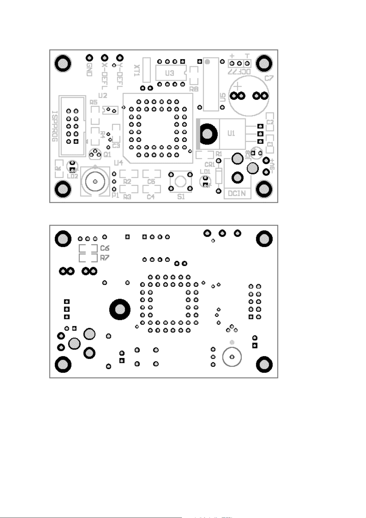
steps below. First read the entire document twice, before starting. At the end of the document
there are two pictures to help you check which parts should go on the top or bottom of the
pcb.
First step is to solder all the resistors. The resistors have numbers printed on them, and you
should not mix them up.
The value of a resistor is printed as a small number, for instance 472. This should be read as
47 plus 2 zero’s, so the value would be 4700 ohms, which is the same as 4K7. It can also be
printed as 4701, meaning 470 plus 1 zero, again 4700 ohms or 4K7. A printed value of 3300
means 330 plus 0 zero’s (!) so that is indeed 330 ohm. When you are in doubt, use a
multimeter and simply measure the value.
The resistors are numbered in increasing order, using designators like R1, R2, R2 etc. Their
values can be found in the schematic and/or component list.
For soldering you need:
a) very thin solder, diameter 0.5 mm. (0.020 inch).
b) insanely good eyesight, or a jewelers loupe, magnifying glass, or cheap +3 reading
glasses.
c) long sharp pointed soldering tip. 25-30 watt iron.
d) steady hand.
e) metal tweezers. Make sure the tweezers align properly, adjust them by either bending,
grinding and sanding.
LAST WARNING
Believe it or not, but SMD components are like flees. They can jump hundred times their own
size. Your tweezer has to be absolutely perfect, has to close ‘parallel’. Even the best brand
new tweezers need some bending, sanding, filing, etc. Make sure your table is clean. Make
sure you have enough light. If an SMD components is upside down, don’t try to turn it, it will
jump away. Better is to lift it a couple of centimeters, using the tweezer, and let it drop again.
With some luck, it is now facing up. Also, count all the components in the kit, so you will
know how many have actually jumped away before you could solder them. No kidding!!!
Find a resistor and locate on the PCB where it has to go. First put a tiny bit of solder on one
pad, about 2 mm. of (thin 0.5mm) solderwire is enough. Just make a nice little blob of solder
on one of the pads. Now use the tweezer to place the resistor on the right pads, and reflow the
solder on the pad you have just presoldered. Move away your soldering iron. Now the resistor
won’t move anymore, so you can let go of the tweezer. Solder the other pad, applying a few
mm. of solder. Finally solder the first pad, adding some solder too. If the component has
disappeared mysteriously, it probably hangs on the tip of your soldering iron.
Take your time, and don’t panic. If you don’t get the hang of it after 5 resistors or so, better
stop and ask a friend to help you.