AEMC 6417 User manual

Clamp-on Ground Tester
Model 6417
ENGLISH
USER MANUAL
www.GlobalTestSupply.com
Find Quality Products Online at: sales@GlobalTestSupply.com

Statement of Compliance
Chauvin Arnoux®, Inc. d.b.a. AEMC®Instruments
certifies that this instrument has been calibrated
using standards and instruments traceable to
international standards.
We guarantee that at the time of shipping your
instrument has met its published specifications.
An NIST traceable certificate may be
requested at the time of purchase, or obtained
by returning the instrument to our repair and
calibration facility, for a nominal charge.
The recommended calibration interval for this
instrument is 12 months and begins on the date of
receipt by the customer. For recalibration, please
use our calibration services. Refer to our repair
and calibration section at .
Serial #: ________________________________
Catalog #: 2141.02
Model #: 6417
Please fill in the appropriate date as indicated:
Date Received: _________________________________
Date Calibration Due: _______________________
Chauvin Arnoux®, Inc.
d.b.a AEMC®Instruments
www.GlobalTestSupply.com
Find Quality Products Online at: sales@GlobalTestSupply.com

Clamp-on Ground Resistance Tester Model 6417
1
(1) Clamp-on Ground Tester
Model 6417
Cat. #2141.02
5WCalibration Loop
Cat. #2141.51
Bluetooth Adapter
Cat. #2126.45
Hard Accessory Case
Cat. #2141.50
Quick Start Guide
USB Stick with
DataView®Software & User Manual
PRODUCT PACKAGING
Shipping Contents:
Also Included:
(4) 1.5V AA Batteries
(1) Wrist Strap
(1) Safety Sheet (20 languages)
www.GlobalTestSupply.com
Find Quality Products Online at: sales@GlobalTestSupply.com

2Clamp-on Ground Resistance Tester Model 6417
Thank you for purchasing an AEMC Clamp-on Ground Resistance Tester.
For best results from your instrument and for your safety, read the enclosed
operating instructions carefully and comply with the precautions for use. These
products must be only used by qualied and trained users.
WARNING, risk of DANGER! The operator must refer to these instructions whenever
this danger symbol appears.
CAUTION! Risk of electric shock. The voltage at the parts marked with this symbol
may be dangerous.
Application or withdrawal authorized on conductors carrying dangerous voltages.
Type A current sensor as per IEC 61010-2-032.
Equipment is protected by double insulation.
The product has been declared recyclable after analysis of its life cycle in accordance
with the ISO14040 standard.
Important instructions to read and to fully understand.
Useful information or tip to read.
The CE marking guarantees conformity with European directives and with regulations
covering EMC.
The trash can with a line through it means that in the European Union, the product
must undergo selective disposal for the recycling of electric and electronic material,
in compliance with Directive WEEE 2002/96/EC.
Denition of Measurement Categories (CAT)
CAT IV Measurement Category IV corresponds to measurements taken at the
source of low-voltage installations.
Example: power feeders, counters and protection devices.
CAT III Measurement Category III corresponds to measurements on building
installations.
Example: distribution panel, circuit-breakers, machines or xed
industrial devices.
CAT II Measurement Category II corresponds to measurements taken on
circuits directly connected to low-voltage installations.
Example: power supply to domestic electrical appliances and portable
tools.
www.GlobalTestSupply.com
Find Quality Products Online at: sales@GlobalTestSupply.com

Clamp-on Ground Resistance Tester Model 6417
3
PRECAUTIONS FOR USE
This instrument and its accessories comply with safety standards EN 61010-1,
EN 61010-030, and EN 61010-2-032 for voltages of 600V in Category IV at an
altitude of less than 2000m with a pollution degree of not more than 2.
Failure to observe the safety instructions may result in electric shock, re,
explosion, and destruction of the instrument and of the installations.
■The operator and/or the responsible personnel must carefully read and clearly
understand the various precautions to be taken in use. Sound knowledge
and a keen awareness of electrical hazards are essential when using this
instrument.
■ If you use this instrument other than as specied, the protection it provides
may be compromised, thereby endangering you.
■Do not use the instrument on networks of which the voltage or category
exceeds those mentioned.
■Do not use the instrument if it seems to be damaged, incomplete, or poorly
closed.
■Before each use, check the condition of the insulation on housing. Any item
of which the insulation is deteriorated (even partially) must be set aside for
repair or scrapping.
■Use personal protection equipment systematically.
■ When handling the instrument, keep your ngers behind the physical guard.
■All troubleshooting and metrological checks must be performed by competent
and accredited personnel.
■Avoid impacts on the measurement head, in particular the air gap.
■Keep the surfaces of the air gap clean; even a little dirt can cause the clamp
to malfunction.
■All metal objects or wires connected to the electrical system should be
assumed to be lethal until tested. Grounding systems are no exception.
■Use extreme caution when using the instrument around energized electrical
equipment.
■Never attempt to use the instrument to twist or pry the ground electrode or
ground wire away from the equipment being grounded.
www.GlobalTestSupply.com
Find Quality Products Online at: sales@GlobalTestSupply.com

4Clamp-on Ground Resistance Tester Model 6417
Table of Contents
1. INTRODUCTION .............................................................................................7
1.1 Receiving Your Shipment......................................................................7
1.2 Ordering Information.............................................................................7
1.2.1 Replacement Parts...................................................................7
2. PRODUCT FEATURES .....................................................................................8
2.1 Description............................................................................................8
2.2 Features................................................................................................9
2.3 Applications...........................................................................................9
2.4 Display................................................................................................10
2.5 Control Features .................................................................................12
2.6 Audible Signals ...................................................................................13
2.7 Rotary Switch Functions .....................................................................13
2.8 Button Functions.................................................................................14
3. PRINCIPLE OF OPERATION ..........................................................................15
4. SET-UP .......................................................................................................17
4.1 Menu Items .........................................................................................17
4.2 SET-UP Menu Displays ......................................................................17
4.3 Selecting a Specic Menu ..................................................................18
4.4 SET-UP Menus ...................................................................................18
4.5 Calibration Loop..................................................................................21
5. OPERATION.................................................................................................22
5.1 Inserting the Batteries.........................................................................22
5.2 Setting the Date and Time ..................................................................22
5.3 Display Example .................................................................................23
5.4 Turning the Instrument ON .................................................................23
5.5 Turning Bluetooth ON .........................................................................24
5.6 Turning the Instrument OFF................................................................24
www.GlobalTestSupply.com
Find Quality Products Online at: sales@GlobalTestSupply.com

Clamp-on Ground Resistance Tester Model 6417
5
5.7 Standard and Advanced Modes..........................................................24
5.8 Memory...............................................................................................25
5.8.1 Memory Capacity....................................................................25
5.8.2 Storing Measurements into Memory.......................................25
5.8.3 Reading Stored Data..............................................................25
5.8.4 Erasing the Memory ...............................................................25
5.8.5 Using the ▲ and ▼ Buttons ...................................................26
5.8.6 Exporting Data to a PC...........................................................26
5.9 Alarm Management.............................................................................26
5.9.1 Voltage Alarm .........................................................................26
5.9.2 Current Alarm .........................................................................27
5.9.3 Impedance Alarm....................................................................27
5.9.4 No Alarm Detection.................................................................27
5.9.5 Priority of the Alarms ..............................................................28
6. MEASUREMENT MODES..............................................................................29
6.1 Rotary Position Ω+A...........................................................................29
6.1.1 Standard Mode.......................................................................29
6.1.2 Advanced Mode......................................................................30
6.1.3 General Information................................................................31
6.2 Rotary Position (A)..............................................................................33
6.2.1 Making a Measurement..........................................................33
6.3 Rotary Position - (MR) ........................................................................33
6.3.1 Displaying Stored Measurements...........................................33
7. DATAVIEW®SOFTWARE...............................................................................36
7.1 Installing DataView®............................................................................36
7.2 Ground Clamp Control Panel..............................................................38
8. ANDROID APPLICATION ..............................................................................39
www.GlobalTestSupply.com
Find Quality Products Online at: sales@GlobalTestSupply.com

6Clamp-on Ground Resistance Tester Model 6417
9. SPECIFICATIONS .........................................................................................43
9.1 Reference Conditions .........................................................................43
9.2 Electrical .............................................................................................43
9.2.1 Loop Resistance Measurement..............................................43
9.2.2 Loop Inductance Measurement..............................................44
9.2.3 Contact Voltage (Touch Voltage) ............................................44
9.2.4 Current Measurement.............................................................44
9.2.5 Power Supply .........................................................................45
9.3 Environmental.....................................................................................45
9.4 Mechanical..........................................................................................45
9.5 Safety..................................................................................................46
10. MAINTENANCE..........................................................................................47
10.1 Cleaning............................................................................................47
10.2 Battery Replacement ........................................................................47
10.3 Repair and Calibration......................................................................48
10.4 Technical and Sales Assistance........................................................48
10.5 Limited Warranty...............................................................................49
10.6 Warranty Repairs..............................................................................49
www.GlobalTestSupply.com
Find Quality Products Online at: sales@GlobalTestSupply.com

Clamp-on Ground Resistance Tester Model 6417
7
1. INTRODUCTION
1.1 Receiving Your Shipment
Upon receiving your shipment, make sure that the contents are consistent with
the packing list. Notify your distributor of any missing items. If the equipment
appears to be damaged, le a claim immediately with the carrier and notify
your distributor at once, giving a detailed description of any damage. Save the
damaged packing container to substantiate your claim.
1.2 Ordering Information
Clamp-on Ground Resistance Tester Model 6417 ....................... Cat. #2141.02
Includes a hard carrying case, Bluetooth USB adapter, calibration loop, four 1.5V
AA batteries, quick start guide, and USB stick with DataView®software and user
manual.
1.2.1 Replacement Parts
Bluetooth USB Adapter Class 2........................................................Cat. #2126.45
Wrist Strap........................................................................................Cat. #2135.47
Hard Carrying Case..........................................................................Cat. #2141.50
5W Calibration Loop..........................................................................Cat. #2141.51
Order Accessories and Replacement Parts Directly Online
Check our Storefront at for availability
www.GlobalTestSupply.com
Find Quality Products Online at: sales@GlobalTestSupply.com

8Clamp-on Ground Resistance Tester Model 6417
2. PRODUCT FEATURES
2.1 Description
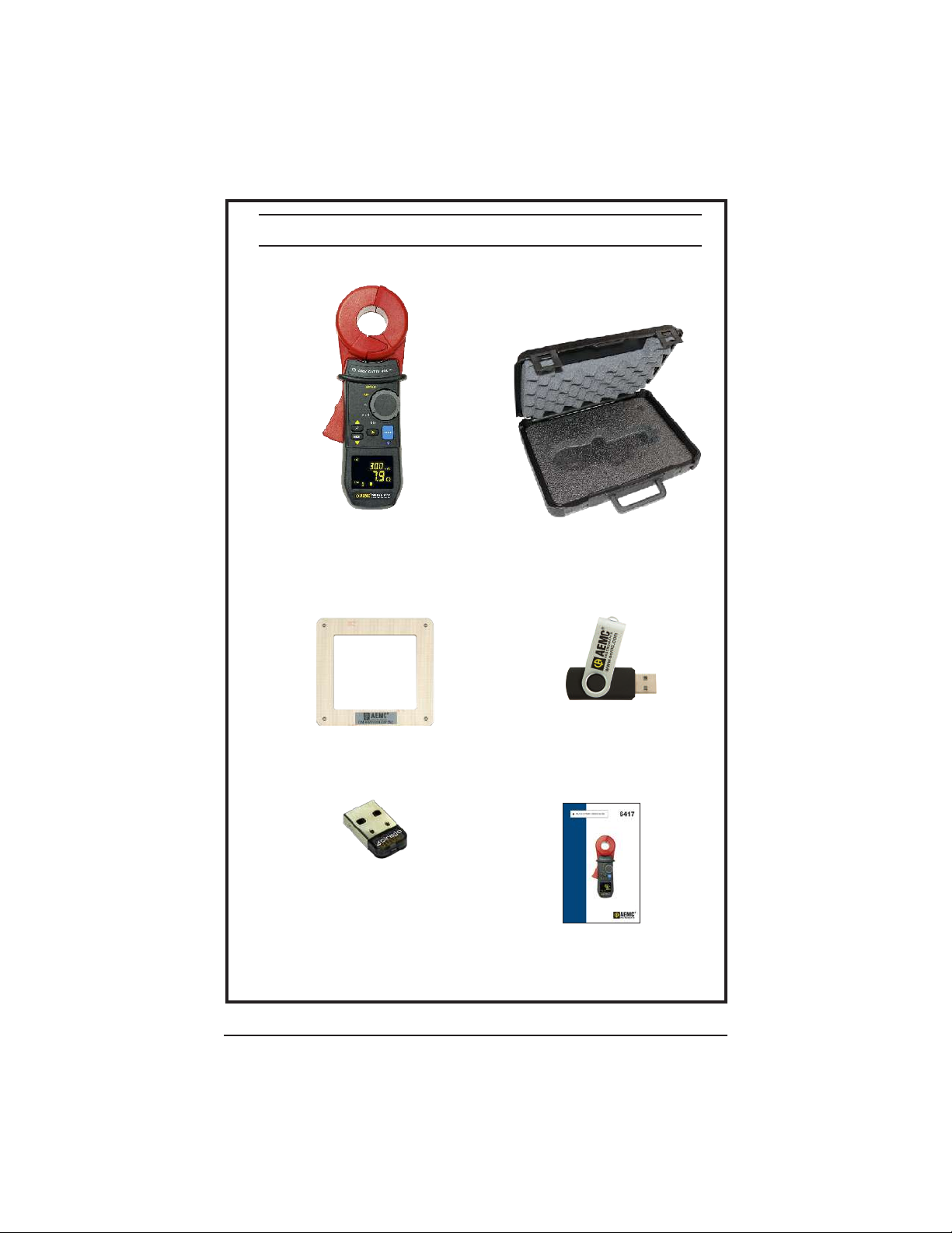
The Clamp-on Ground Resistance Tester Model 6417 measures grounding
electrodes and grid resistance without the use of auxiliary rods. Clamp-on ground
resistance testers can be used in multi-grounded systems without disconnecting
the ground system under test. The Model 6417 simply clamps around the
ground conductor or rod and measures the resistance to ground. By performing
measurements on intact ground systems, the user also veries the quality of the
grounding connections and bonds. Resistance and continuity of grounding loops
around pads and buildings can also be measured.
The Model 6417 includes a current measurement function. The ground tester’s
high sensitivity enables measurement of leakage current owing to ground or
circulating in ground loops from 0.2mA to 40A and resistances from 0.01 to
1500W.
Battery life information is displayed at power-up and the Auto Power OFF feature
can be enabled for power management. Additional features include the large
OLED (Organic Light Emitting Diode) display that ensures high readability of
data. The Buzzer and Auto Power OFF features can be disabled at any time.
The Model 6417 is equipped with an alarm function and a data storage function.
In the Alarm mode, the probe will audibly and visually indicate when the reading
is beyond an input set point. You can also have the alarm activate above or
below the set point. This alarm feature permits quick eld checks where only
“pass” or “fail” readings are required.
The data storage function logs up to 2000 measurements (Wand/or A). This
enables you to conduct eld surveys, and to retrieve and analyze the readings at
a later time. The alarm settings and stored data are saved on the ground tester
and remain stored even when the instrument is turned OFF. You can retrieve and
analyze the results at a later time with DataView®software or with an Android app
through the Bluetooth communication port.
Two new features unique to AEMC®are test frequency selection and touch
voltage indication.
The ability to select the test frequency provides more accurate measurements in
inductive environments.
Displaying voltage derived from current and resistance measurements provides
an extra level of safety for the user, indicating a potentially dangerous touch
condition.
www.GlobalTestSupply.com
Find Quality Products Online at: sales@GlobalTestSupply.com

Clamp-on Ground Resistance Tester Model 6417
9
2.2 Features
■Simple and fast clamp-on operation - no leads, no auxiliary rods or spacing
requirements
-Ammeter: Current measurements from 0.2mA to 40A.
-Loop ohmmeter: Measurement of loop impedances from 0.01 to 1500W.
The ohmmeter function makes allowance for the presence of inductances
in the loop, making impedance measurements more accurate at low
values.
-Contact voltage: The contact voltage is determined by calculating the
product of the loop impedance and leakage current. The value found is an
upper bound on the voltage between the measurement point and earth,
since the impedance taken into account is that of the whole loop.
■Touch voltage display
■Large multi-function, bright yellow organic light emitting diode display (OLED)
■Display in Standard mode (one screen) or Advanced mode (three screens)
■Clamping diameter of 1.38" (35mm) accommodating cables up to 1000kcmil
■Stores up to 2000 measurements (Wand/or A, with time-stamping)
■Displays stored measurements on the display or via Bluetooth®to a PC
■Measurement hold by the HOLD and AUTO-HOLD functions
■Clamp opening made easy by a trigger with a force compensation system
■Auto Power OFF function
■ Alarm function with adjustable set point and buzzer for quick eld checks
■Rugged Lexan®head and body construction resists breakage
■Alarm settings and stored memory information saved during shutdown
■NOISE icon and buzzer notify the user to presence of dangerous voltage and
current levels
■Designed to EN 61010-1, 600V CAT IV safety standards
2.3 Applications
■Ground electrode system resistance
■Bonding/continuity checks
■ Cell tower grounding verication
■Ground measurements on Railroad signaling systems
www.GlobalTestSupply.com
Find Quality Products Online at: sales@GlobalTestSupply.com

10 Clamp-on Ground Resistance Tester Model 6417
2.4 Display
The Model 6417 is equipped with a 152-segment OLED (organic light-emitting
diode) display. This OLED technology results in a thinner, lighter, sharper, higher
contrast display compared to LCD displays.
1
2
3
4
5
6 7 8910 11 12
13
14
15
16
171819
202122
Figure 2-1
Item Description
1Indicates selection of Advanced mode.
2In Advanced mode, this indicates when the inductive component is negligible with
respect to the resistive component.
3
Main Display:
-Measurement of the impedance or current.
-Display of the date and time (month-day and hour-minute) in configured and
stored values display mode.
4In Advanced mode, these symbols identify the value displayed (resistance or
impedance).
5Data storage mode.
6Memory recall mode.
7
Memory index four-digit digital display (0 to 9999-counts):
-Measurement sequence number of the current memory in normal operation
associated with the Recall (MR) or Storage (MEM) indications.
-Date stamp (year) when the device is configured.
8-ON steady when Bluetooth is enabled but not connected to the computer.
-Blinks when the Bluetooth connection is established.
9Signal indicating potentially hazardous voltage. Blinks when the contact voltage
exceeds 50V.
www.GlobalTestSupply.com
Find Quality Products Online at: sales@GlobalTestSupply.com

Clamp-on Ground Resistance Tester Model 6417
11
10
Alarm threshold high/low indicator (operational use or configuration):
▲Alarm threshold high indicator.
AL Alarm threshold adjustment mode or Alarm function.
▼Alarm threshold low indicator.
11
Alarm threshold display:
-Display of one of the alarms (1000-count display) with units.
-These three digits are also used when configuring the time display mode.
(A for A.M., P for P.M. or 24H) in SET-UP (see § 4.4, menu #8).
12
Unit of the alarm displayed. The alarm can be defined on a resistance impedance,
voltage, or current, depending on the measurement chosen (W+A or A).
-A: Current measurement alarm.
-W:Resistance measurement alarm.
-V: Voltage measurement alarm.
13
Unit of the central measurement display:
-V: Contact voltage measurement unit.
-W:Impedance measurement unit. Symbol used for impedances at the
measurement frequency, for impedances referred to the network frequency, or
for the resistive component.
14
Unit of the top measurement display:
-mH: Loop inductance measurement unit.
-mA or A: Current measurement unit.
15 Upper display: 4000-count current measurement and 500-count loop inductance
measurement (Advanced mode).
16
Battery charge indicator:
-Not displayed: Batteries charged.
-Blinking: Batteries low. The device remains functional, but the batteries will
have to be replaced soon.
-Steady: Batteries discharged. The display indicates Lo bat. It is not possible to
make measurements, read records, or configure parameters.
17 Continuous operation of the clamp (Auto Power OFF disabled).
Selection of Auto Power OFF mode is made in SET-UP (see § 4.4, menu #3).
18
Symbol indicating incorrect closing of the clamp; measurements cannot be made
in this case. If the AUTO-HOLD mode is activated, the HOLD icon blinks and the
measurement is frozen. Selection of AUTO-HOLD mode is made in SET-UP (see § 4.4,
menu #11).
19 Symbol indicating the presence of disturbance (current) in the loop, which
compromises the accuracy of the impedance measurement.
20 Indicates that the main display shows the date (when the rotary switch is set to MR
or SET-UP).
21 Indicator of freezing the measurement display when the HOLD button is pressed or
while in the AUTO-HOLD mode.
22 Display of the buzzer’s active state; the icon is not shown when the buzzer is inactive.
Selection of the buzzer operating mode is made in SET-UP (see § 4.4, menu #2).
www.GlobalTestSupply.com
Find Quality Products Online at: sales@GlobalTestSupply.com

12 Clamp-on Ground Resistance Tester Model 6417
2.5 Control Features
MEM
HOLD
OFF
A
MR
SET-UP
6
0
0
V
C
A
T
I
V
4
0
A
1
2
38
9
4
5
6
7
Figure 2-2
1. Head Assembly: Consists of two individually shielded magnetic cores
2. Guard: Safety guard; do not place hands above this guard
3. Lever: Opens or closes the jaws
4. : Toggles display backlight ON/OFF
5. MEM: Stores measurements into memory
6. ►:Navigates and validates measurement displays
7. OLED Display: Crisp, clean and bright display
8. Rotary Switch: Selects measurement functions and instrument SET-UP
9. HOLD: Freezes last measured value on the display
Turns Bluetooth ON/OFF (when switch is set to MR or SET-UP)
www.GlobalTestSupply.com
Find Quality Products Online at: sales@GlobalTestSupply.com

Clamp-on Ground Resistance Tester Model 6417
13
2.6 Audible Signals
There are four audible signals:
Type Duration Description
Low-pitched Short Normal use (button pressed).
Permanent High/Low alarm threshold (W, A) triggered.
High-pitched Short Abnormal use (for example, memory full).
Permanent Alarm threshold (V) exceeded.
Audible signals can be enabled or disabled in SET-UP (see § 4.4, menu #2).
The symbol indicates:
Description
Visible Buzzer enabled; an alarm or a button press causes an audible signal to be
emitted.
Not Visible No audible signal is emitted.
This programming is backed-up and retrieved at each reset.
During a measurement, a long press on the ► button toggles between activation
and deactivation of the buzzer.
NOTE: Since the measurement frequency is audible, the operator hears a beeping
signal. This is neither an operating fault nor an alarm, and it cannot be eliminated.
This audible signal is amplified by the presence of current in the loop.
2.7 Rotary Switch Functions
Range Description
OFF Instrument is powered OFF.
Ω+A Simultaneous selection of the loop impedance measurement and the leakage
current measurement.
ACurrent measurement selection
MR Displays stored measurements.
SET-UP Access to the instrument configuration and deletion of stored measurements.
www.GlobalTestSupply.com
Find Quality Products Online at: sales@GlobalTestSupply.com

14 Clamp-on Ground Resistance Tester Model 6417
2.8 Button Functions
Button Description
▲
• When the rotary switch is set to W+A or A: Increases the brightness
of the display, making it easier to read the display in an environment with
strong background illumination. Highlighting activated for 30 seconds.
• When the rotary switch is set to SET-UP or MR: Serves as the ▲
arrow when browsing in the menus and values. The brightness of the
display does not change when device is set to SET-UP or MR.
MEM
▼
• When the rotary switch is set to W+A or A: Records the measured
value. All of the data is recorded in the Standard or Advanced mode.
• When the rotary switch is set to SET-UP or MR: Serves as the ▼
arrow when browsing in the menus and values.
►
• When the rotary switch is set to W+A (Advanced Mode):
Short Press: Switches the display through the following three modes:
-Display of the impedance recalculated at the selected frequency.
-Display of the contact voltage (product Z*I).
-Display of R and L.
Long Press: Enables or disables the audible alarms.
• When the rotary switch is set to SET-UP:
-Validation when browsing in the menus and values.
• When the rotary switch is set to MR (Advanced Mode):
-Switches the display through the measurement screens and the
measurement date/time.
HOLD
&
AUTO-HOLD
• When the rotary switch is set to W+A:
-Freezes the displayed measurement for as long as the HOLD button
is pressed. The NOISE, clamp open ( ), and alarm exceedence ( )
icons are visible, if they were active.
• When the rotary switch is set to MR or SET-UP:
-Enables or disables the Bluetooth®connection.
• AUTO-HOLD Function:
If the AUTO-HOLD mode was enabled during instrument SET-UP (see
§ 4.4, menu #11), opening the clamp acts as the identical state to the
HOLD mode for as long as the clamp is open. The benefit of this function
is that it makes it easy to freeze the measurement with one hand, when
access to the HOLD button is difficult.
If the HOLD button is not pressed during this time, closing the clamp
automatically exits the AUTO-HOLD mode.
www.GlobalTestSupply.com
Find Quality Products Online at: sales@GlobalTestSupply.com

Clamp-on Ground Resistance Tester Model 6417
15
3. PRINCIPLE OF OPERATION
Typically, a grounded distribution system can be simulated by the basic circuit
shown in Figure 3-1 or an equivalent to the diagram shown in Figure 3-2. If
voltage (V) is applied to any measured grounding electrode Rx through a
special transformer; current (I) ows through the circuit, thereby establishing the
following equation:
V
I= Rx +
1
Σ
n
i=1
1
Ri
Rx »
1
Σ
n
i=1
1
Ri
where, usually
Therefore, V/I = Rx is established. If I is detected and measured with V kept
constant, the measured grounding electrode resistance Rx can be obtained.
A signal is fed to a special transformer via a power amplier from a 2403Hz
constant voltage oscillator. The resulting current is then sensed by a detection
CT (current transformer). An active lter is used to dampen earth current at
commercial frequency (50/60Hz) and high-frequency noise.
Example: If clamped around any grounding electrode in a multi-grounded
system, the measured value of the electrode under test will be the resistance
of that particular rod in series with the equivalent parallel resistance value that
the rest of the multi-grounded system represents. If an electrical system had
101 grounding electrodes and each had a resistance value of 25W, and it were
clamped around any electrode in the system, the measured value would be 25W
in series with the equivalent parallel resistance of the other 100 electrodes or
0.25W. The displayed value would be 25.2W(instrument resolution to 0.1W).
V/I = 25W+ 0.25W
Rx = 25.2W
In most eld applications, the number of electrodes that make up a multi-
grounded system would be higher; therefore the equivalent parallel resistance is
negligible with respect to the rod under test.
I
V
Rx R1R2Rn-1 Rn
Figure 3-1
www.GlobalTestSupply.com
Find Quality Products Online at: sales@GlobalTestSupply.com

16 Clamp-on Ground Resistance Tester Model 6417
RxR1RnRn-1
Figure 3-2
www.GlobalTestSupply.com
Find Quality Products Online at: sales@GlobalTestSupply.com

Clamp-on Ground Resistance Tester Model 6417
17
4. SET-UP
Turn the rotary switch to the SET-UP position.
4.1 Menu Items
The SET-UP position gives access to the following options to set user dened
parameters for instrument conguration:
No. Function
1Erases stored measurements.
2Enables/disables the buzzer.
3Enables/disables Auto Power OFF
4Sets the impedance alarm threshold (W).
5Sets the voltage alarm threshold (V).
6Sets the current alarm threshold (I).
7Sets the date.
8Sets the time.
9Selects the Standard or Advanced operating mode.
10 Selects the test frequency for the impedance.
11 Enables/disables the AUTO-HOLD mode.
12 Displays the version number.
13 Not used.
4.2 SET-UP Menu Displays
The 12 accessible menus (listed
above) are clearly identied by their
title and number, as shown in the
example in Figure 4-1 (menu #5)
which displays the voltage alarm
threshold adjustment (AL. V).
Figure 4-1
www.GlobalTestSupply.com
Find Quality Products Online at: sales@GlobalTestSupply.com

18 Clamp-on Ground Resistance Tester Model 6417
4.3 Selecting a Specific Menu
Use the buttons as follows to select a specic menu item:
Button Action
▲Move up in the menu tree.
▼Move down in the menu tree.
►Select the menu displayed or return to the previous menu.
NOTE: When changes have been made in one of the SET-UP menus, the changes
can be cancelled by turning the rotary switch to a position other than SET-UP,
provided that there has not been a return to the main menu (by pressing ►).
4.4 SET-UP Menus
Menu # Indication Function
1CLr
Erasing the Memory:
■ Enter the menu by ►. Clr blinks.
■ Press ▲ and ▼ simultaneously for 6 seconds. All
recorded data is erased. The meter indicates
MEM 0.
■ Return to the previous menu by ►.
2Snd
Enabling/Disabling the Buzzer:
■ Enter the menu by ►. Snd blinks.
■ Press ▲ or ▼.
■The Buzzer is enabled when the icon is visible
and disabled when it is masked.
■ Return to the previous menu by ►.
NOTE: In the Ω+A and A measurement modes, a long
press on ► activates or deactivates the audible alarms.
3StOP
Enabling/Disabling Auto Power OFF:
■ Enter the menu by ►. StOP blinks.
■ Press ▲ or ▼.
■Auto Power OFF is deactivated when the icon is
visible and activated when it is hidden.
■ Return to the previous menu by ►.
www.GlobalTestSupply.com
Find Quality Products Online at: sales@GlobalTestSupply.com
Other manuals for 6417
3
Table of contents
Other AEMC Test Equipment manuals
Popular Test Equipment manuals by other brands

Sourcetronic
Sourcetronic TM-25R user guide

Superchips
Superchips 2705 MAX Micro Tuner Programming instructions

iCool
iCool LITE owner's manual

Koehler
Koehler K185 Series Operation and instruction manual

Agilent Technologies
Agilent Technologies 85056A User's and service guide

Murideo
Murideo MU-M4SOL user manual