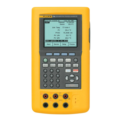
Fluke 730G User manual

730G, 730GA, 730RG
Pressure Calibrators
Users Manual
October 2018 (English)
© 2018 Fluke Corporation. All rights reserved. Specifications are subject to change without notice.
All product names are trademarks of their respective companies.

LIMITED WARRANTY AND LIMITATION OF LIABILITY
Each Fluke product is warranted to be free from defects in material and workmanship under normal use and
service. The warranty period is three years and begins on the date of shipment. Parts, product repairs, and
services are warranted for 90 days. This warranty extends only to the original buyer or end-user customer of a
Fluke authorized reseller, and does not apply to fuses, disposable batteries, or to any product which, in Fluke's
opinion, has been misused, altered, neglected, contaminated, or damaged by accident or abnormal conditions of
operation or handling. Fluke warrants that software will operate substantially in accordance with its functional
specifications for 90 days and that it has been properly recorded on non-defective media. Fluke does not warrant
that software will be error free or operate without interruption.
Fluke authorized resellers shall extend this warranty on new and unused products to end-user customers only but
have no authority to extend a greater or different warranty on behalf of Fluke. Warranty support is available only if
product is purchased through a Fluke authorized sales outlet or Buyer has paid the applicable international price.
Fluke reserves the right to invoice Buyer for importation costs of repair/replacement parts when product purchased
in one country is submitted for repair in another country.
Fluke's warranty obligation is limited, at Fluke's option, to refund of the purchase price, free of charge repair, or
replacement of a defective product which is returned to a Fluke authorized service center within the warranty
period.
To obtain warranty service, contact your nearest Fluke authorized service center to obtain return authorization
information, then send the product to that service center, with a description of the difficulty, postage and insurance
prepaid (FOB Destination). Fluke assumes no risk for damage in transit. Following warranty repair, the product will
be returned to Buyer, transportation prepaid (FOB Destination). If Fluke determines that failure was caused by
neglect, misuse, contamination, alteration, accident, or abnormal condition of operation or handling, including
overvoltage failures caused by use outside the product’s specified rating, or normal wear and tear of mechanical
components, Fluke will provide an estimate of repair costs and obtain authorization before commencing the work.
Following repair, the product will be returned to the Buyer transportation prepaid and the Buyer will be billed for the
repair and return transportation charges (FOB Shipping Point).
THIS WARRANTY IS BUYER'S SOLE AND EXCLUSIVE REMEDY AND IS IN LIEU OF ALL OTHER
WARRANTIES, EXPRESS OR IMPLIED, INCLUDING BUT NOT LIMITED TO ANY IMPLIED WARRANTY OF
MERCHANTABILITY OR FITNESS FOR A PARTICULAR PURPOSE. FLUKE SHALL NOT BE LIABLE FOR ANY
SPECIAL, INDIRECT, INCIDENTAL OR CONSEQUENTIAL DAMAGES OR LOSSES, INCLUDING LOSS OF
DATA, ARISING FROM ANY CAUSE OR THEORY.
Since some countries or states do not allow limitation of the term of an implied warranty, or exclusion or limitation
of incidental or consequential damages, the limitations and exclusions of this warranty may not apply to every
buyer. If any provision of this Warranty is held invalid or unenforceable by a court or other decision-maker of
competent jurisdiction, such holding will not affect the validity or enforceability of any other provision.
11/99
Fluke Corporation
P.O. Box 9090
Everett, WA 98206-9090
U.S.A.
Fluke Europe B.V.
P.O. Box 1186
5602 BD Eindhoven
The Netherlands
ООО «Флюк СИАЙЭС»
125167, г. Москва,
Ленинградский проспект дом 37,
корпус 9, подъезд 4, 1 этаж
LIMITED WARRANTY AND LIMITATION OF LIABILITY
i
Table of Contents
Title Page
Introduction ........................................................................................................... 1
How to Contact Fluke............................................................................................ 1
Safety Information................................................................................................. 2
Standard Equipment ............................................................................................. 4
Display .................................................................................................................. 5
Control Panel ................................................................................................... 6
Function Keys .................................................................................................. 6
Connections..................................................................................................... 7
Connect and Zero the Product.............................................................................. 8
Menus ................................................................................................................... 9
Main Menu ....................................................................................................... 9
Instrument Setup ............................................................................................. 9
Date/Time ................................................................................................... 10
Measure Mode Menu....................................................................................... 10
Volt Mode ................................................................................................... 11
mA Mode .................................................................................................... 11
mA+24V Mode............................................................................................ 12
Leakage Test ................................................................................................... 12
Error Test......................................................................................................... 13
Min Max Value ................................................................................................. 14
Switch Test ...................................................................................................... 14
HART Communication (HART)........................................................................ 15
HART Connections Internal Loop Power, Internal Resistance................... 18
External Loop Power, Internal Resistance ................................................. 19
External Loop Power, External Resistance ................................................ 20
Data Memory ................................................................................................... 21
Accessories........................................................................................................... 21
Maintenance ......................................................................................................... 21
Clean the Product ............................................................................................ 22
Charge the Battery........................................................................................... 22
Replace the Battery ......................................................................................... 23
Specifications........................................................................................................ 24
Accuracy Specifications................................................................................... 24
Mechanical Specifications ............................................................................... 25
Electrical Specifications ................................................................................... 25
Environmental Specifications........................................................................... 25
Safety............................................................................................................... 26
Ranges and Resolutions.................................................................................. 27

730G, 730GA, 730RG
Users Manual
ii

1
Introduction
The Fluke 730G, 730GA, and 730RG Pressure Calibrators (the Product) are portable field pressure calibration
tools for lab or field use. The battery-operated product performs pressure calibration of transmitters, pressure
switches, pressure sensors, and gauges with pressure calibration software. The Product also supplies basic
HART® communicator functions when used with HART-capable transmitters.
Key features and benefits include:
• Pressure calibration of transmitters, pressure switches and pressure gauges.
• Test and calibrate pressure sensors, transmitters, and other pressure instruments.
• HART (Highway Addressable Remote Transducer) communication to configure trim on HART smart-
pressure transmitters.
• Provide Loop Power and simultaneously measure mA output from a connected device.
• Measure mA and voltage.
• An internal HART resistor to turn on or off when used with HART transmitters.
How to Contact Fluke
To contact Fluke, call one of the following telephone numbers:
• Technical Support USA: 1-800-44-FLUKE (1-800-443-5853)
• Calibration/Repair USA: 1-888-99-FLUKE (1-888-993-5853)
• Canada: 1-800-36-FLUKE (1-800-363-5853)
• Europe: +31 402-675-200
• Japan: +81-3-6714-3114
• Singapore: +65-6799-5566
• China: +86-400-921-0835
• Brazil: +55-11-3530-8901
• Anywhere in the world: +1-425-446-5500
Or, visit Fluke's website at www.fluke.com.
To register your product, visit http://register.fluke.com.
To view, print, or download the latest manual supplement, visit http://us.fluke.com/usen/support/manuals.
To request a printed manual, vist www.fluke.com/productinfo.

730G, 730GA, 730RG
Users Manual
2
Safety Information
A Warning identifies hazardous conditions and procedures that are dangerous to the user. A Caution identifies
conditions and procedures that can cause damage to the Product or the equipment under test.
XW Warning
To prevent possible electrical shock, fire, or personal injury and for safe operation of the
Product:
• Read all safety information before you use the Product.
• Carefully read all instructions.
• Do not use the Product around explosive gas, vapor, or in damp or wet environments.
• Do not alter the Product and use only as specified, or the protection supplied by the Product
can be compromised.
• Do not apply more than the rated voltage, between the terminals or between each terminal and
earth ground.
• Do not touch voltages >30 V ac rms, 42 V ac peak, or 60 V dc.
• Do not use the Product if it is damaged.
• Disable the Product if it is damaged.
• Do not use the Product if it operates incorrectly.
• Use the correct terminals, function, and range for measurements.
• Remove all probes, test leads, and accessories before the battery door is opened.
• The battery door must be closed and locked before you operate the Product.
• Examine the case before you use the Product. Look for cracks or missing plastic. Carefully
look at the insulation around the terminals.
• Do not use test leads if they are damaged. Examine the test leads for damaged insulation,
exposed metal, or if the wear indicator shows. Check test lead continuity.
• Only assemble and operate high-pressure systems if you know the correct safety procedures.
High-pressure liquids and gases are hazardous and the energy from them can be released
without warning.
• Have an approved technician repair the Product.
• Do not disassemble or crush battery cells and battery packs.
• Batteries contain hazardous chemicals that can cause burns or explode. If exposure to
chemicals occurs, clean with water and get medical aid.
• Do not put battery cells and battery packs near heat or fire. Do not put in sunlight.
• Use only Fluke approved power adapters to charge the battery.
• Disconnect the battery charger and move the Product or battery to a cool, nonflammable
location if the rechargeable battery becomes hot (>50 °C) during the charge period.
• Replace the rechargeable battery after 5 years of moderate use or 2 years of heavy use.
Moderate use is defined as recharged twice a week. Heavy use is defined as discharged to
cutoff and recharged daily.
• Do not disassemble the battery.
• Do not short the battery terminals together.

Pressure Calibrators
Safety Information
3
• If the display reads “OL” the range limit is exceeded and the pressure source must
immediately be reduced. The Product shows “OL” when the pressure exceeds 110 % of the
nominal range of the sensor. Pressure sensors can be damaged and personnel injury can
occur due to improper application of pressure.
• Push 1 to zero the pressure sensor when vented to atmospheric pressure.
W Caution
To prevent damage to the Product or to equipment under test:
• If the display reads “OL” the range limit is exceeded and the pressure source must
immediately be reduced.
• Always apply thread seal tape to the threads of the gauge.
• Do not exceed the maximum torque allowed. Maximum torque allowed is 13.5 Nm = 10 lbft.
Note
Before you use the Product for the first time, see Charge the Battery.
Table 1 lists the symbols that can be used on the Product or in this manual.
Table 1. Symbols
Symbol Description
Consult user documentation.
WWARNING. RISK OF DANGER.
XWARNING. HAZARDOUS VOLTAGE. Risk of electric shock.
fPressure.
Battery status. Battery charging when animated.
On/Off
PConforms to European Union directives.
Conforms to relevant Australian Safety and EMC standards.
Conforms to relevant South Korean EMC standards.
This Product contains a lithium-ion battery. Do not mix with the solid waste stream. Spent
batteries should be disposed of by a qualified recycler or hazardous materials handler per
local regulations. Contact your authorized Fluke Service Center for recycling information.
~
This product complies with the WEEE Directive marking requirements. The affixed label
indicates that you must not discard this electrical/electronic product in domestic household
waste. Product Category: With reference to the equipment types in the WEEE Directive
Annex I, this product is classed as category 9 "Monitoring and Control Instrumentation"
product. Do not dispose of this product as unsorted municipal waste.

730G, 730GA, 730RG
Users Manual
4
Standard Equipment
Table 2 shows the standard equipment that comes with the Product.
Table 2. Standard Equipment
Item Description Item Description
The Product GFitting, 1/4 in NPT-Female x 1/4 in
BSP-Male
Rechargeable lithium-ion battery pack HAlligator clip red
AC power supply/battery charger IAlligator clip black
DUniversal power adapters (not available
in all countries) JUSB cable
ETest lead set
Not shown
Traceable calibration report with data
FFitting, 1/4 in NPT-Female X M20-Male Safety Information and Quick
Reference Guide
10K PSI
700 BAR
2
4
5
1
8
9
3
7
10
6

Pressure Calibrators
Display
5
Display
Table 3 shows the items on the display.
Table 3. Display
Item Description Item Description
Mode display EMeasured voltage, current, or
temperature value
Time and date display FSoft keys
Battery status GPressure range bar graph
DMeasured pressure value
7.000
psi
20.000
V
100%0%
MEAS V 17/07/30 15:30
Zero Save Menu mA
3
1
4
6
7
5
2

730G, 730GA, 730RG
Users Manual
6
Control Panel
Use the control panel to select functions and options. Table 4 lists the functions of the buttons on the control
panel.
Function Keys
Use the function keys to change parameters or select functions and options. Table 5 lists the main functions of
the function keys.
Table 4. Control Panel
Item Description Function
Power button Push to turn on or off the Product.
Backlight button Push to turn on or off the backlight of the display.
Function keys Push to perform the function listed on the softkey above the function
key. See Function Keys.
Table 5. Function Keys
Button Home Screen Function Menu Function
Zero the pressure value. See Connect
and Zero the Product.
Select the highlighted item to:
Open a submenu.
Or
Save the change and go back to the previous
screen.
Take a screen shot of the display. See
Data Memory.Highlight the previous item in the menu.
Open the main menu. Highlight the next item in the menu.
Toggle between current measurement
and voltage measurement. Go back to the previous screen.
10K PSI
700 BAR
7.000
psi
20.000
V
100%0%
MEAS V 17/07/30 15:30
Zero Save Menu mA
2
3
1

Pressure Calibrators
Display
7
Connections
Table 6 shows the connections of the Product.
Table 6. Connections
Item Description Function
COM port Provide common ground.
V or mA port
Measure mA or V dc.
Or
Supply loop power.
Ac power supply/battery
charger input
Supply the Product with power.
Or
Charge the battery while the battery is installed in the Product.
DUSB input Communicate between the Product and a PC.
EPressure port Connect the Product to a device that supplies pressure.
3
5
4
2
1

730G, 730GA, 730RG
Users Manual
8
Connect and Zero the Product
Connect and zero the Product prior to use and calibration.
To set up the Product:
1. Wrap the threads of the pressure port with PTFE tape.
2. Connect the pressure port of the Product to an output of an approved pump. See Figure 1.
Note
Follow the directions of the manufacturer of the pump for use with the Product.
3. Connect a device to test to another output of the pump. See Figure 1.
4. Vent the pressure of the pipe.
5. Push to zero the Product.
Figure 1. Product Setup with Pump and Gauge
300
400
psi
500
600
200
100
0
7.000
psi
20.000
V
100%0%
MEAS V 17/07/3015:30
Zero Save Menu mA

Pressure Calibrators
Menus
9
Menus
Use the menus to change and view settings.
Main Menu
Table 7 lists the submenus available in the main menu.
Instrument Setup
Use the Instrument Setup (Setup) menu to set user preferences and view information about the Product. Table 8
lists the options in the Setup menu.
Table 7. Main Menu
Submenu Description
Measure Mode Set the measurement mode. See Measure Mode Menu.
Leakage Test Test a device for leaks. See Leakage Test.
Error Test Perform an error test on transmitters. See Error Test.
Min Max Val Display the maximum or minimum pressure and current, voltage, or temperature
values. See Min Max Value.
Switch Test Calibrate a pressure switch and save the results of the test. See Switch Test.
HART Comm. (HART
Communication) Communicate with a HART transmitter. See HART Communication (HART).
Data Memory View data stored in memory. See Data Memory.
Instru. Setup (Instrument
Setup)
Set user preferences and view information about the Product. See Instrument
Setup.
Table 8. Setup Menu
Item Option Description
Contrast -Decrease the contrast of the display.
+Increase the contrast of the display.
Pressure Unit <options> Set the pressure units to show on the display. See Specifications
for a list of available units.
Date/time <options> Set the date and time. See Date/Time.
Beeper On
Enable the beeper function.
With the beeper enabled, the beeper beeps:
Once when you push a button.
Twice for an invalid selection.
Off Disable the beeper function.

730G, 730GA, 730RG
Users Manual
10
Date/Time
To set the date and time:
1. Select Menu > Instrument Setup > Date/time.
2. Set each field:
a. Push / to highlight the field to change.
b. Push to select the field.
c. Push (-) to decrease the value, or push (+) to increase the value.
d. Push to set the value.
e. Push to return to the previous screen.
3. Push twice to set the changes and return to the previous menu.
Measure Mode Menu
Table 9 lists the options in the Measure Mode menu.
Power off
Never
Set the time after which the Product automatically turns off when
there is no user interaction.
5 minutes
15 minutes
30 minutes
Factory mode -- Reset the Product to original settings.
Language <options> Set the language.
Device info. -- Show the Product information on the display.
Table 9. Measure Mode
Item Description
Volt Measure V dc. See Volt Mode.
mA Measure mA. See mA Mode.
mA+24V Measure mA and supply 24 V loop power. See mA+24V Mode.
Temperature
Measure internal temperature of the Product.
In Temperature mode, the Product shows the internal temperature of the Product
and the pressure measurement.
Table 8. Setup Menu (cont.)
Item Option Description

Pressure Calibrators
Menus
11
Volt Mode
In Volt mode, the Product shows the pressure and loop voltage measurements. Figure 2 shows the voltage
measurement connections.
Figure 2. Volt dc Measurement Connections
mA Mode
In mA mode, the Product shows the pressure and loop current measurements without 24 V power enabled.
Figure 3 shows the mA measurement connections with a non-HART device.
Figure 3. mA Measurement Connections with a non-HART device
10K PSI
700 BAR
7.000
psi
20.000
V
100%0%
MEAS V 17/07/30 15:30
Zero Save Menu mA
Voltage
Output Device
10K PSI
700 BAR
7.000
psi
20.000
mA
100%0%
MEAS mA 17/07/30 15:30
Zero Save Menu Volt
4mA - 20mA
Output Device 4mA - 20mA

730G, 730GA, 730RG
Users Manual
12
mA+24V Mode
In mA+24V mode, the Product outputs 24 V dc as it shows the pressure and loop current measurements. Use
this mode to power a transmitter without a separate power supply. Figure 4 shows the mA+24V Mode
connections.
Figure 4. mA Measurement with 24 V Loop Power Connections
Leakage Test
To do a leakage test:
1. Connect and zero the Product. See Connect and Zero the Product.
2. Select Menu > Leakage Test.
3. To start the test, push .
4. To stop the test, push .
The Product shows the result. The results include time elapsed for the test. The leakage rate unit shows as */min.
Figure 5 shows the formula used to calculate the leakage rate.
Figure 5. Leakage Rate Calculation
Leakage Rate = Pressurestart - Pressurestop
time (minute)
10K PSI
700 BAR
7.000
psi
4.000
mA
100%0%
MEAS mA
24V 17/07/30 15:30
Zero Save Menu Volt

Pressure Calibrators
Menus
13
Error Test
Do an error test to check for pressure leaks in the device under test (DUT). Table 10 lists the options in the Error
Test menu.
To do an error test:
1. Connect and zero the Product. See Connect and Zero the Product.
2. Select Menu > Error Test.
3. Configure the measurement mode.
a. Push to set the measurement mode.
b. Push / to highlight the unit of measure to test.
c. Push to set the value and return to the previous screen.
4. Configure the pressure and electrical ranges.
a. Push to set the pressure range or to set the electrical range.
b. Set each value.
1. Push / to highlight the value to change.
2. Push to select the value.
3. Push / to highlight the numerical value to change.
4. Push to select the numerical value.
5. Push to decrease the value, or push to increase the value.
6. Push to set the value.
7. Push to set the change and return to the previous screen.
c. Push twice to set the changes and return to the previous menu.
The results automatically show on the display. The results include the pressure measured, the electrical value
measured, and the error percentage.
Figure 6 shows the formula used to calculate the current error percentage.
Table 10. Error Test
Item Option Description
Cfg. M (Configure
Measurement Mode)
Volt
Set the measurement mode to use for the error test.mA
mA+24V
Cfg. P (Configure
Pressure Range)
Set 100% Pressure Value Set the pressure range to use for the error test.
Set 0% Pressure Value
Cfg. E (Configure
Electrical Range)
Set 100% Volt or mA Value Set the electrical range to use for the error test
based on the selection of the measurement mode.
Set 0% Volt or mA Value

730G, 730GA, 730RG
Users Manual
14
Figure 6. Current Error Percentage Calculation
Figure 7 shows the formula used to calculate the voltage error percentage.
Figure 7. Voltage Error Percentage Calculation
Min Max Value
To view the minimum or maximum pressure, electrical, and temperature values:
1. Connect and zero the Product.
2. Select Menu > Min Max Val.
3. Start a pressure test.
The minimum measured values show on the display while the test runs.
4. Push to view the maximum measured values on the display. Push to view the minimum
values again.
5. Push to discard the saved measured values and save new minimum and maximum values.
Switch Test
Use the Product to calibrate a pressure switch.
To do a pressure switch test:
1. Connect and zero the Product. See Connect and Zero the Product and Figure 8.
2. Select Menu > Switch Test.
The Product defaults to test a normal open type switch. To toggle between normal open and normal closed
type switches, push (Re-do).
3. Use the pump to increase the pressure to a selected value.
When the pressure reaches the selected value, the switch closes and the Product saves the pressure value.
For a normal closed type switch, the switch opens and the Product saves the pressure value.
4. Use the pump to decrease the pressure to a selected value.
When the pressure reaches the selected value, the switch opens and the Product saves the pressure value.
For a normal closed type switch, the switch closes and the Product saves the pressure value.
Error % = Pressuremeasure - Pressure4mA Currentmeasure - 4 mA
Pressure20mA - Pressure4mA 16 mA
Error % = Pressuremeasure - Pressure1V Voltagemeasure - 1 V
Pressure5V - Pressure1V 5 V - 1 V

Pressure Calibrators
Menus
15
Figure 8. Switch Connection
HART Communication (HART)
Use the Product to communicate with HART devices.
Auto power off is disabled when you use the HART menus. When you exit the HART menus, auto power off
returns to its previous state.
Note
Loop output trim is supported for transmitter devices, but it is not supported for actuator devices.
Type
7.000
psi
SWITCH 17/07/30 15:30
Re-do Save Back
------
open close
------ ------

730G, 730GA, 730RG
Users Manual
16
Table 11 lists the items in the HART menu.
Table 12 lists the items in the Cont. (Continue) menu. The Cont. menu shows the measured values of the HART
device that is connected to the Product.
Table 11. HART Menu
Item Option Description
Select
Cont. (Continue) View the measured values of the HART device connected to the
Product. See Table 12.
Svc. (Service) Service the HART device. See Table 13.
Setup Set up the HART device. See Table 14.
Back Return to previous screen.
24V On/
24V Off --
Toggles on and off 24V loop power.
When the soft key shows 24V Off and 24V shows on the top of the
display, the Product supplies loop power.
When the soft key shows 24V On, use an external source to supply
loop power.
R On/
R Off --
Toggles on and off the internal HART resistor of the Product.
When the soft key shows R Off and R shows on the top of the
display, the Product supplies 250 Ω resistance to the circuit.
When the soft key shows R On, use an external 250 Ω resistance.
Back -- Return to previous screen.
Table 12. Cont. (Continue) Menu
Item Description
Tag View the HART device tag.
PV View the primary variable measured by the HART device.
PVAO View the primary variable analog output.
PV URV View the upper range value of the primary variable.
PV LRV View the lower range value of the primary variable.
PV % Range View the percent of PV to PV range.
[(PV - PV LRV) / (PV URV - PV LRV)] * 100
SV View the secondary variable measured by HART device.
TV View the tertiary variable measured by HART device.
QV View the quaternary variable measured by HART device.
This manual suits for next models
3
Table of contents
Other Fluke Test Equipment manuals

Fluke
Fluke 4322 User manual

Fluke
Fluke 71X Series Use and care manual

Fluke
Fluke MS2-100-IE User manual

Fluke
Fluke 5730A/03 User manual

Fluke
Fluke 165X User manual

Fluke
Fluke 5820A User manual

Fluke
Fluke 1550C User manual

Fluke
Fluke FiberInspector Pro FI-7000 User manual

Fluke
Fluke 9132A User manual

Fluke
Fluke ULT800 User manual

Fluke
Fluke 39 User manual

Fluke
Fluke T3 Use and care manual

Fluke
Fluke MicroScanner 2 User manual

Fluke
Fluke i1000s Use and care manual

Fluke
Fluke P3000 Series User manual

Fluke
Fluke 9009 User manual

Fluke
Fluke TL2X4W-TWZ User manual

Fluke
Fluke SPOT Light User manual

Fluke
Fluke CertiFiber Pro User manual

Fluke
Fluke TP1000 Original instructions