Franke CT-200 User manual

1
INSTALLATION MANUAL
CT-200

2
CT-200
Under Sink Chiller Unit Installation Instructions and Use and Care Guide
CHILLER SAFETY
Your safety and the safety of others are very important.
We have provided many important safety messages in this manual and on your appliance. Always read
and obey all safety messages.
This is the safety alert symbol.
This symbol alerts you to potential hazards that can kill or hurt you and others.
All safety messages will follow the safety alert symbol and either the word "DANGER" or "WARNING".
These words mean:
You can be killed or seriously injured if you don’t immediately follow instructions.
You can be killed or seriously injured if you don’t follow instructions.
All safety messages will tell you what the potential hazard is, tell you how to reduce the chance of
injury, and tell you what can happen if the instructions are not followed. You can be killed or seriously
injured if you don’t follow instructions.
ASSISTANCE OR SERVICE
If you need assistance or service, first see “Troubleshooting” section. Additional help is available by
calling 1-800-626-5771 or write:
Franke Kitchen Systems
Luxury Products Group
800 Aviation Parkway
Smyrna, TN 37167
Please include a daytime phone number in your correspondence. For installation and service, call:
1-800-626-5771 or visit our website at www.frankeksd.com.
Keep this book and your sales slip together for future reference. You must provide proof of purchase
or installation date for in-warranty service. Write down the following information about your appliance
to help you obtain assistance or service if you need it. You will need to know your complete model
number. You can find this information on the model and serial number label.
Dealer Name____________________________________________________________________
Address________________________________________________________________________
Phone Number________________________________ Model Number_______________________
Purchase Date___________________________________________________________________
DANGER
WARNING

3
CT-200
Under Sink Chiller Unit Installation Instructions and Use and Care Guide
1
2
4
3
5
6
7
8
9
10
11
12
13
TECHNICAL DATA
Water temperature 50°F
Chiller capacity 1 gal/hr
Supply voltage 115 VAC
Frequency 60 Hz
Minimum water pressure 30 psi
Maximum water pressure 100 psi
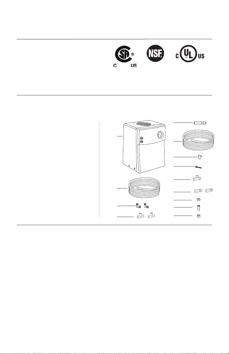
CONTENTS IN BOX
Call immediately if you see inconsistencies (1-800-626-5771) or visit www.frankeksd.com
1. Chiller unit
2. 4' blue poly tubing
3. (2) elbow push fittings
4. (2) 1/4" x 1/4" x 1/4" x T push fittings
5. Check valve
6. 6' white poly tubing
7. Wall mounting clip
8. #7 phillips screw
9. (1) 3/8" x 3/8" x 1/4" T push fitting
10. (2) 3/8" x 1/4" reducer fittings
11. 1/4" compression ferrule
12. 1/4" compression insert
13. 1/4" compression nut
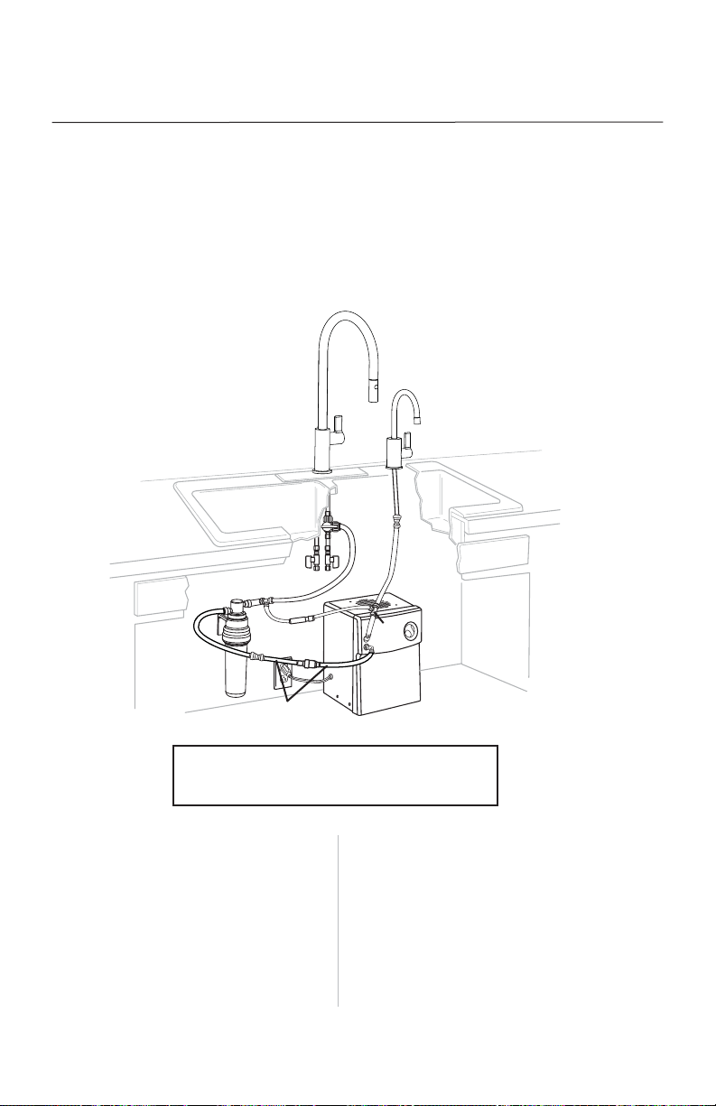
INSTALLATION REQUIREMENTS
IMPORTANT: For best results, Franke recommends its products to be installed by a licensed, professional
plumber. The installer should familiarize themselves with how this chiller will be installed. Make certain to
observe all local plumbing and building codes during installation of this unit. Inspect location where the
chiller will be installed. Proper installation is the responsibility of the installer. Make sure you have everything
necessary for the correct installation. Water connections use push fittings that DO NOT require any types of
sealing compounds to prevent leakage. Use of any sealing compounds will VOID THE PRODUCT WARRANTY.
This chiller is not a water purifier. For water purification, Franke separately offers and strongly recommends
using the chiller with our line of professional under counter filtration products to enhance water quality, and
improve performance and durability of the chiller. These instructions are written assuming the use of the
Franke filtration products.
This chiller must be used in conjunction with a drinking water dispensing faucet, also sold separately.
Franke recommends pairing this chiller with one of our Little Butler®of point of use dispensing faucets,
as outlined in these instructions.
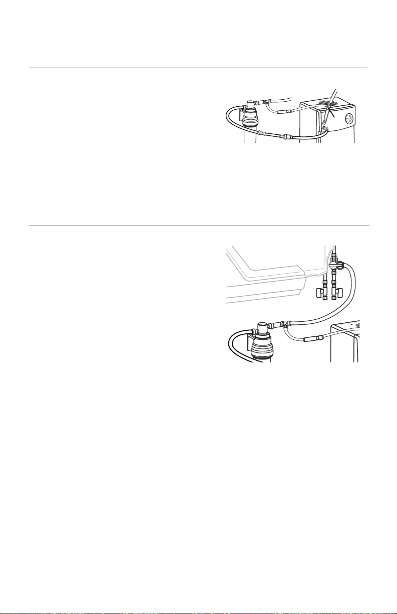
For installations with high water pressure, or fluctuations in water pressure, Franke recommends using
our SB60 pressure safety valve (sold separately) to control pressure to the chiller.
This product is certified to ASME A112.19.3/CSA B45 for stainless steel
plumbing fixtures, NSF/ANSI Standard 61, Annex G for lead content, which
is in compliance with California’s Health and Safety Code Section 116875
(commonly known as AB1953), and UL399 for drinking water coolers.

4
CT-200
Under Sink Chiller Unit Installation Instructions and Use and Care Guide
LOCATION REQUIREMENTS
Determine where the chiller and all components being used in the installation should be mounted beforehand
and make sure there is adequate clearance for plumbing and electrical components and there is enough
tubing to reach the intended mounting positions. For best performance, position the chiller to allow a 2" (5 cm)
space around the top and sides. Do not put any objects on top of the chiller that could obstruct the fan.
WARNING
ELECTRICAL REQUIREMENTS
A 120-volt, 60-Hz, 15- or 20-amp, grounded electrical supply is
required. It is recommended that a separate circuit serving only
your chiller unit be provided. Use an outlet that cannot be
turned on/off by a switch.
RECOMMENDED GROUND METHOD
The chiller must be grounded. This appliance is equipped with
a power supply cord with a 3 prong ground plug. To minimize
possible shock hazard, the cord must be plugged into a mating,
3 prong, ground-type outlet, grounded in accordance with all
national and local codes and ordinances. If a mating outlet is
not available, it is the personal responsibility and obligation
of the customer to have a properly grounded, 3 prong outlet
installed by a qualified electrician.
ELECTRICAL SHOCK HAZARD
Plug into a grounded 3 prong outlet.
Do not remove ground prong.
Do not use an adapter.
Failure to follow these instructions can
result in death, fire, or electrical shock.
WATER SUPPLY REQUIREMENTS
A cold water supply with a minimum pressure of 30 psi and a maximum pressure of 100 psi must be available
to the chiller. It can come directly from the water supply of the home, or from a water filtration system. A
Franke filtration system is highly recommended.
INSTALLATION INSTRUCTIONS
IMPORTANT: For subsequent steps, it will be required to cut and route tubing to fit the specific application in
your home. All tubing must be cut squarely and free of burrs. Ensure there is no damage within 1" of the cut end.
Insert the tubing squarely. See Figure A.
Make sure to insert tubing completely. See Figure B.
To remove, push in collet and pull out tubing See Figure C.
Figure A Figure B Figure C
Tube Collet Body
DO NOT USE ANY FORM OF SEALING
COMPOUNDS, this is not required for
push fit connections, and using sealing
compounds could cause leaks. All
tubing connections must be firmly
seated. Tubing must be routed to avoid
sharp bends and have enough slack to
avoid straining connections. A P-clip
and mounting screw is included to
hold the tubing in place as needed.
Pull gently on each connection to
make sure they are secure. See
Diagram 1 for details on tubing
installation and removal.
HOW TO INSERT/REMOVE TUBING
IN PUSH FIT CONNECTIONS
DIAGRAM 1

1.
2.
3.
4.
5.
6.
7.
8.
9.
10.
11.
12.
13.
14. 15.
16.
13.
5
CT-200
Under Sink Chiller Unit Installation Instructions and Use and Care Guide
INSTALLATION INSTRUCTIONS
The following instructions pertain to the connection of this chiller to a Franke filtration system and Franke Little
Butler®series dispensing faucets. The connection options for all compatible Franke products will be reviewed
in this document. Make sure you understand which connection option applies to your specific installation.
Diagram 2 illustrates a general overview of the entire installation for ALL COLD ONLY Little Butler®
dispensing faucets.
1. Chiller unit
2. 1/4" tee push fitting
3. 1/4" blue tubing
4. Franke Little Butler®cold only faucet
(sold separately)
5. Cold water supply from home
6. Hot water supply from home
7. 1/4" white tubing
8. Franke filtration system (sold separately)
9. 10306 shut-off valve (sold separately)
10. 3/8" x 3/8" x 1/4" push fitting
11. Check valve
12. 3/8" tubing
13. 3/8"-1/4" reducer push fitting or 1/4"
compression fitting (not shown)
14. SB60 pressure safety valve (sold separately)
15. 1/4" elbow push fitting
16. Franke kitchen faucet (sold separately)
DIAGRAM 2:
COLD ONLY LITTLE BUTLER DISPENSING FAUCET
12.
12.
7.

6
CT-200
Under Sink Chiller Unit Installation Instructions and Use and Care Guide
INSTALLATION INSTRUCTIONS
1. After chiller is unpacked, place upright for 24 hours before plugging it in.
2. Ensure the water supply is turned off.
3. Install a suitable drinking water dispensing faucet (sold separately) per the instructions. The following
steps outline how the chiller is to be connected to a Franke COLD ONLY Little Butler®dispensing
faucet. Any other faucet may require additional steps or hardware to install.
4. Connect the 3/8" black tubing (12) from the exit of
the Franke filtration system (8) to the 3/8" to 1/4"
reducer push fitting (13). Cut a piece of the white
1/4" poly tubing (7) long enough to connect the
reducer push fitting to the “water in” connection
on the chiller. If the SB60 pressure safety valve
(14) is utilized, insert it between the 3/8" to 1/4"
reducer push fitting (13) and the elbow push
fitting (15). If not utilized, connect the tubing (7)
from the reducer push fitting (13) to one of the
elbow push fittings (15), and connect the other
end of the elbow push fitting to the “water in”
connection on the chiller.
5. Next connect the other elbow push fitting (15) to
the “water out” connection on the chiller. Cut a
piece of the blue 1/4" poly tubing (3) long enough
to connect to the 1/4" tee push fitting (2). The tee
push fitting (2) may be connected directly to the
chiller “water out” connection in place of the
elbow push fitting (15) if your particular installation
has room to do this. Connect blue 1/4" tubing (3)
to the side of the tee push fitting (2) going to the
inlet of the drinking water faucet.
1.
8.
12.
13.
14. 15.
15.
2.
“Water in” connection
“Water out” connection
7.
3.
3.

Option 3:
For DW13050 dispensing faucet models:
Connect the 1/4" tubing (3) from the chiller (1)
directly to the cold water inlet of the dispensing
faucet (4).
7
12.
13.
4.
3.
15.
1.
Option 1:
For DW50XX, DW61XX, DW70XX, DW80XX,
and DW90XX dispensing faucet models:
Connect the 1/4" tubing (3) from the chiller to
a 3/8" to 1/4" reducer push fitting (13) and
use the black 3/8" tubing supplied with the
dispensing faucet (12) to connect the dispensing
faucet (4) to the 3/8" side of the reducer push
fitting (13).
Option 2:
For DW100XX, DW110XX, and DW120XX
dispensing faucet models:
Slide the compression nut (20) and plastic ferrule
(19) and onto the 1/4" tubing (3) from the chiller
(1). Slide the plastic insert (18) into the end of
the 1/4" tubing from the chiller. Insert the tubing
with compression fitting hardware attached into
the mounting nipple (17) of the faucet (4) and
tighten the compression nut (20).
4.
3.
15.
1.
17.
18.
19.
20.
3.
4.
3.
15.
1.
CT-200
Under Sink Chiller Unit Installation Instructions and Use and Care Guide
6. Connect the 1/4" tubing (3) from the “water out” tee push fitting (2) from the chiller (1) to
the faucet (4). This step will vary, based on dispensing faucet being connected. Identify the
faucet you are connecting and follow the appropriate instruction:
2.

8
CT-200
Under Sink Chiller Unit Installation Instructions and Use and Care Guide
7. If you are NOT installing a filtration system with
the chiller, please refer to the "setup of chiller
without filtration system" on page 9. Connect
the 1/4" white tubing (7) to the other side of
the tee push fitting (2). Connect the other end
of the tubing to the check valve (11). Make sure
the check valve (11) is oriented with the arrow
pointing in the direction of the flow, towards the
tee push fitting (10). Then cut a short piece of
1/4" tubing and connect the check valve (11) to
the 3/8" x 3/8" x 1/4" tee push fitting (10).
8. Connect a piece of 3/8" tubing from one outlet of
the tee push fitting (10) to the inlet of the filtration
system (8). Connect another piece of 3/8" tubing
from the other outlet of the tee push fitting (10) to
the cold water supply of the home (5). Franke
recommends using a 10306 shut-off valve (9) that
allows for connection directly to the kitchen
faucet as illustrated.
10.
11. 7. 2.
11.
9.
5.
7.
10.
8.

9
CT-200
Under Sink Chiller Unit Installation Instructions and Use and Care Guide
4.
16.
9.
6. 5.
12.
12.
14.
15.
13.
13.
1.
SETUP OF CHILLER WITHOUT THE FILTRATION SYSTEM
IMPORTANT: The check valve helps to avoid the possibility of excessive pressure building as the chiller cycles
on and off. If you are NOT installing the chiller with a filtration system, do NOT use tee push fitting (2), check
valve (11), or tee push fitting (10) illustrated in step 7. The setup without the check valve would look like the
Diagram 3.
DIAGRAM 3
9. Slowly turn on water supply. Open the cold water valve and allow the dispensing faucet to run for at
least 1 minute. Check all connections for leaks.
10. Plug in the chiller to a suitable power supply (see electrical requirements section). Prior to drinking
water, flush water through chiller for at least 5 minutes.
USAGE
SETTING THE TEMPERATURE
- Your chiller has a dial for water temperature control.
- For colder water: Turn it clockwise (to the right).
- For less cold water: Turn it counterclockwise (to the left).
- To shut down the chiller: Turn the dial to the Off position at full counterclockwise (extreme left).
- Allow one hour to obtain chilled water.

10
CT-200
Under Sink Chiller Unit Installation Instructions and Use and Care Guide
TROUBLESHOOTING
Problem
Water is not cold.
Cold water drips or sputters from spout.
Water does not flow from spout.
Unpleasant taste.
Check the Following
- Check that the circuit breaker has not tripped or the house fuse
has not blown.
- Check that power supply cord is plugged into electrical outlet.
- Check if the electrical outlet is operated by a switch.
The switch may have turned the power off.
- Cold water in tank is still being chilled. Wait 15 minutes and
check temperature again.
- Check that the Temperature Control is set to the “Max” setting.
- Check that tubing is not bent or kinked.
- Make sure main supply valve is open.
- Check that water pressure to the chiller is 30 psi (138 kPa)
minimum.
- Check to see if chiller is attached to hot water line. If so, attach to
cold water line.
- Check filters for proper installation.
- If the dispenser has not been used for 3 or more days or if only 1
to 3 cups of water are dispensed in a day, the tank may need to be
purged. Open the faucet for 2 to 3 minutes to purge the old water
from the tank. Allow new water in tank to reach desired
temperature (approximately 1 hour) before dispensing water.
- Check to see if filtration element in filtration system needs to be
replaced
MAINTENANCE
DISCONNECTING AND STORAGE
1. Unplug the chiller.
2. Shut off water supply to chiller.
3. Open faucet to release pressure.
4. Disconnect the water lines attached to the chiller by depressing collet on push fittings.
5. Tip chiller to the left side (power cord side) and drain water into a large container.
6. Set chiller in its normal upright position for storage.
RECONNECTING THE CHILLER
1. Shut off water supply to chiller.
2. Put chiller back in position, allowing a 2" (5 cm) space around the side and top.
3. Connect chiller as described in the “Installation Instructions” section.
4. Slowly open main water supply valve and open faucet until water flows.
5. Plug in chiller and set dial to desired water temperature (See the “Setting the Temperature” section).

11
CT-200
Under Sink Chiller Unit Installation Instructions and Use and Care Guide
WARRANTY
Congratulations on the purchase of this Franke product! Franke is one of the world’s largest manufacturers of
kitchen systems. Our products are manufactured using the highest degree of technology, quality and design.
As a result, we are proud to offer the following warranty:
Warrantor: Franke Kitchen Systems Luxury Products Group, 800 Aviation Parkway, Smyrna, TN 37167
ONE-YEAR LIMITED WARRANTY
The Warrantor promises the original purchaser to repair or replace, at the Warrantor’s option, any part of this
CT-200 Chiller unit that proves to be inoperative due to a defect in material or workmanship under normal use,
for a period of one (1) year from the date of purchase. This warranty will be honored provided the CT-200
Chiller unit has been installed and operated in accordance with the written instructions furnished with the
CT-200 Chiller unit.
GENERAL PROVISIONS AND EXCLUSIONS
This warranty applies only within Canada and the United States of America. This warranty will be honored if
the unit is returned in the original carton (or suitable replacement) along with proof of purchase. This warranty
does not apply to bonus and/or accessory items sold with the CT-200 Chiller unit. This warranty does not
apply if the affixed serial number is removed, defaced or obliterated. This warranty does not cover poor
performance, failure or damage of any part resulting from external causes such as alterations, abuse, misuse,
misapplication, corrosion, liming conditions or acts of God. This warranty and the Underwriter’s Laboratory or
Canadian Standard Association listing for this CT-200 Chiller unitare automatically voided if this CT-200 Chiller
unit is altered, modified or combined with any other machine or device. Alteration or modification of this
CT-200 Chiller unit may cause serious flooding, and/or hazardous electrical shock or fire.
Except as set forth herein or required by law, the Warrantor makes no other warranty, guarantee or
agreement, express, implied or statutory, including any IMPLIED WARRANTY OF MERCHANTABILITY
OR FITNESS FOR A PARTICULAR PURPOSE. The Warrantor does not assume or authorize any person
to assume any obligations of liability in connection with this product. In no event will the Warrantor be
liable for indirect, special or consequential damages (including, without limitation, economic loss) or
for any delay in the performance of this agreement due to causes beyond its control. Some states or
provinces do not allow limitations on how long an implied warranty lasts, so the above limitation may
not apply to you. Some states or provinces do not allow the exclusion or limitation of incidental or
consequential damages, so the above limitation or exclusion may not apply to you. This warranty gives
you specific legal rights, and you may also have other rights which vary from state to state or from
province to province.
If you need service, first see Troubleshooting Solutions. Additional help can be found by calling our customer
service line at 1-800-626-5771 or by writing: CT-200 filtration system, Franke Kitchen Systems Luxury
Products Group, 800 Aviation Parkway, Smyrna, TN 37167.

Franke Kitchen Systems
Luxury Products Group
800 Aviation Parkway
Smyrna, TN 37167
800-626-5771
www.frankeksd.com
Part No. INST-CT-200
Print 6/2015
© 2015 Franke Consumer Products, Inc.
All rights reserved. Printed in USA.
Other manuals for CT-200
1
Table of contents
Other Franke Chiller manuals
Popular Chiller manuals by other brands

LG
LG ACHH Series manual

CLIVET
CLIVET MSRT-XSC3 Installation and operating manual

Johnson Controls
Johnson Controls YORK YLCA 40 user manual

Carrier
Carrier 19XL series installation instructions

Carrier
Carrier 30RB-170R Installation, operation and maintenance instructions

TICA
TICA TCAV-BHE Installation & operation manual

EAS Electric
EAS Electric ECH R32 Series Installation and user manual

Parker Hiross
Parker Hiross Hyperchill ICE007 user manual

York
York YCAS0250 Wiring diagram

CLIVET
CLIVET WSAT-XSC3 260.6-480.8 Installation and operating manual

York
York YCAS Series Installation operation & maintenance

Comet
Comet XRCA-3023-WA manual