manuals.online logo
Brands
  1. Home
  2. •
  3. Brands
  4. •
  5. Franke
  6. •
  7. Control System
  8. •
  9. Franke DVS UC07-001 Manual

Franke DVS UC07-001 Manual

Page 8
MT04-001 AquariTherm Tap (Manual) www.dartvalley.co.uk
Revision No. MAQTIN16071301
Step 7 : Time settings and basic operation
Step 6 : Option setup
Urinal Control System
Installation & Operating Instructions
UC07- 001
PP00-151 270619
PP00-151 270619
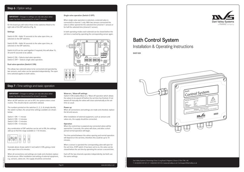
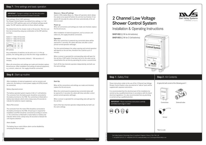
On the board you will notice three in-line switches fitted to the
right side of the DIP switches (Fig. 4). Only switch A is used.
Option switch A (when switched ON) provides two functions, a
pre-flush and a purge option.
The pre-flush opens the valve for 1 second after the first 2
seconds of detection. This helps to prevent splashing by wetting
the urinal bowl. After the pre-flush the timing continues.
The purge is initiated every 12 hours of non-use on either channel.
This helps reduce smells from the urinal during periods of non-
use.
Settings:
Switch A ON = Pre-flush plus purge
Whilst the unit is still powered down the time settings can be
setup.
The numbers printed on the switches (1, 2, 3, 4) simply identify
the switch number; the actual time settings available are shown
below:
Switch 1 ON = 1 seconds
Switch 2 ON = 2 seconds
Switch 3 ON = 4 seconds
Switch 4 ON = 8 seconds
Example above (Fig 5) shows switch 2 and 3 ON. This gives a total
flush-time of 6 seconds
Testing the sensors
A test routine is included for verifying the operation of the
sensors.
After installation of external equipment, the supply should be
connected.
ON
12 34
To put the unit into test mode set DIP switches 1-4 to the OFF
position.
When power is applied LED’s 2 and 3 (Fig 2) will switch on
corresponding to an object within range. For example, if sensor
1 (left hand channel) detects and object in range then LED 3 (left
hand LED) will be on as long as the sensor detects the object.
Sensor 2 operates LED 2 as above. This routine helps to identify if
the sensors are detecting unwanted objects.
Operation:
When a person comes into range of a sensor a counter starts
and after 10 seconds it is determined that the person is an actual
user.
When the person leaves the sensing range the corresponding
valve is opened for the set flush-time. However, a 2 second delay
is built into the counter to allow the person to leave the range
and return after or before the 10 seconds without effect on
the counter. This also means that the valve will not open for 2
seconds after the user has left the area.
Each of the two channels operates independently, but both use
the same settings.
Page 4
IMPORTANT : Changes to settings can only take place when
power has been disconnected for at least 5 seconds.
IMPORTANT : Changes to settings can only take place when
power has been disconnected for at least 5 seconds.
Dart Valley Systems | Kemmings Close | Long Road | Paignton | Devon | TQ4 7TW | UK
T +44 (0)1803 529 021 | F +44(0)1803 559 016 | www.dartvalley.co.uk | techsupport@dartvalley.co.uk
C
ON ON ON
BA
1 2 3 4
Page 3
MT04-001 AquariTherm Tap (Manual) www.dartvalley.co.uk
Revision No. MAQTIN16071301
Page 2
MT04-001 AquariTherm Tap (Manual) www.dartvalley.co.uk
Revision No. MAQTIN16071301
The control box should be located in a dry location and not
exposed to dirt, dust or damp. The unit should be accessible when
required, but not within easy reach of unauthorised persons.
It will be necessary to make adjustments and service the control
box after installation, and in the future. Secure access areas and
duct spaces are recommended.
The control box is not designed for direct surface mounting into
washroom areas. Never open the cover with the supply live.
The routes that cables will take when connecting external
equipment to the control box should also be planned at this stage.
Step 3 : Typical installation
Step 2 : Kit ContentsStep 1 : Safety First
These instructions relate to the use of the Urinal Control System
only, any external or ‘add-on’ parts will be supplied with separate
instructions.
It is recommended that the electrical part of the installation be
carried out by a qualified electrician in accordance with the latest
electrical regulations. It is also recommended that any plumbing
is carried out by a qualified plumber.
*Not to scale
Step 5 : Fixing & wiring
Step 4 : Board layout
915 12 10 11
14
13
43876521
The box should be securely fixed in a suitable location in a
horizontal orientation, so that the front label is read correctly.
Remove lid to expose four fixing locations around the edge of the
enclosure (see Fig. 3). These areas allow the fastening of the unit
without removing the printed circuit board.
Drill through these marked areas away from the wall to avoid dust
entering the control box, then hold control box in position against
the wall and mark holes with a pencil. Remove box, drill and plug
marked areas and fix the control unit with suitable fixings.
Connect the mains supply lead to a 230V ac supply via a fused
spur, the fuse rating should be 3 Amps. The mains supply should
NOT be initiated until all external equipment has been installed
and wired.
Always read instructions supplied with external components and
ensure that only the supplied equipment is connected to the
control box.
Cables should enter the enclosure through the cable glands. Keep
all connections tidy and do not allow cable to finish or hang in the
transformer area.
It is recommended that each cable is fed through the relative
cable gland into the enclosure; the cable can then be pulled out
towards the fitter to allow the connector plugs to be fitted.
The connector plugs can be disconnected from the mating
sockets when wiring external equipment, double check positions
with the plug orientations as they only fit one way!
When each plug has been wired the cables can be pulled back
through the cable glands, and the plug re-connected to the
corresponding socket. Cables should not be left to torte or slack.
When all connections are made and checked, replace the lid and
secure.
Fixing locations
Fuse
Connector plug
Fixing screw
Sensor
Solenoid valve
Control box
A typical kit will include the following parts*:
Control box
15mm pipe
Air break (1.5m
min between
urinal bowl outlet
and air break)
22mm pipe
Urinal sensor
(make sure pipes
are clear of
sensor)
Urinal bowl
IPS panel
Pipework
Isolator
Filter / y-strainer
Solenoid valve
Balancing valve
IMPORTANT : Sensor must be fitted approx. 10cm above the
urinal bowl or a maximum of 120cm from the finished floor.
*Not to scale
(Spare Secondary Fuse Included)
IMPORTANT : Please read these instructions carefully
and follow each stage in order!
Always isolate
power when
opening the
control unit!
IMPORTANT : The control should be connected to a clean,
dedicated mains supply, via a 3A rated spur
16
DO NOT extend cables
DO NOT leave badly fitted cables
DO NOT interfere with the mains flex
DO check all cables and connections
DO ask for advice if / when necessary
Input connection - Sensor 1
Output connection - Valve 1
Input connection - Sensor 2
Output connection - Valve 2
Cable entry - Sensor 1
Cable entry - Valve 1
Cable entry - Sensor 2
Cable entry - Valve 2
Mains supply
Time setting switches
Option switches
LED 1 - For engineers / testing only
LED 2 - For engineers / testing only
LED 3 - For engineers / testing only
Fuse (Primary) PP00-100 (Replace with exact same type)
Primary 20mm Glass 240V (T) 100mA
Fuse (Secondary) PP00-101 (Replace with exact same type)
Secondary TR5 (F) 500mA
1
2
3
4
5
6
7
8
9
10
11
12
13
14
15
16

Other Franke Control System manuals

Franke DVS SH07-001 Manual

Franke

Franke DVS SH07-001 Manual

Franke DVS SH07-020 Manual

Franke

Franke DVS SH07-020 Manual

Franke DVS SH07-002 Manual

Franke

Franke DVS SH07-002 Manual

Popular Control System manuals by other brands

Cheetah Xi Programming manual

Cheetah

Cheetah Xi Programming manual

Norac UC4+ installation manual

Norac

Norac UC4+ installation manual

Hydronix Hydro-Control HC07 installation guide

Hydronix

Hydronix Hydro-Control HC07 installation guide

Balboa Instruments VSP-VS510SZ-DCAH Tech sheet

Balboa Instruments

Balboa Instruments VSP-VS510SZ-DCAH Tech sheet

Festo CPX-AP Series operating instructions

Festo

Festo CPX-AP Series operating instructions

Sky Elevator Sky 301-VS Troubleshooting

Sky Elevator

Sky Elevator Sky 301-VS Troubleshooting

THERMEx Pro Link I Series instructions

THERMEx

THERMEx Pro Link I Series instructions

Thermoline Scientific STAR-700 Operating guidelines

Thermoline Scientific

Thermoline Scientific STAR-700 Operating guidelines

ZAPbp BP93p Operator's manual

ZAPbp

ZAPbp BP93p Operator's manual

Siemens SIMATIC PCS 7 Function manual

Siemens

Siemens SIMATIC PCS 7 Function manual

Turnstiles Traffic H1 operating instructions

Turnstiles

Turnstiles Traffic H1 operating instructions

RTMOTION MK3 user guide

RTMOTION

RTMOTION MK3 user guide

Crestron Prodigy PMC2 System user's guide

Crestron

Crestron Prodigy PMC2 System user's guide

Sea-Fire 131-440 Installation instructions & owner's manual

Sea-Fire

Sea-Fire 131-440 Installation instructions & owner's manual

Exhausto VEX160 Series Original instructions

Exhausto

Exhausto VEX160 Series Original instructions

Russound A-BUS brochure

Russound

Russound A-BUS brochure

FAAC J355HA M30-P1 user manual

FAAC

FAAC J355HA M30-P1 user manual

Madas XV(F)-1-3-6 manual

Madas

Madas XV(F)-1-3-6 manual

manuals.online logo
manuals.online logoBrands
  • About & Mission
  • Contact us
  • Privacy Policy
  • Terms and Conditions

Copyright 2025 Manuals.Online. All Rights Reserved.