Franke ACEX9001 User manual

NETZTEIL
ACEX9001 | 2030039477
PRODUKTGRUPPE : Wassermanagement | ARTIKELFAMILIE : Zubehör
Netzteil für zentrale stabilisierte Gleichstrom-Versorgung. Im Kunststoffgehäuse für Hutschienenmontage. Kurzschlussfeste
Ausführung, mit Sicherheitsabschaltung für angeschlossene bistabile Magnetventile.
Eingangsspannung: 100-240 V AC
Ausgangsspannung: 7 V DC oder 12 V DC (umschaltbar)
Schutzart: IP 20
Leistung: 31,5 W oder 50 W
Wichtiger Hinweis:
Das Netzteil ist zur zentralen Spannungsversorgung von bis zu insgesamt 16 Armaturen der Produktlinien AQUACONTACT
(Betriebsspannung 7 V DC), F3E und F5E (Betriebsspannung jeweils 12 V DC) geeignet. Die Anzahl der Armaturen und die
maximale Kabellänge ist von der Installationsart und dem Kabelquerschnitt abhängig.
TECHNISCHE DATEN
Bruttogewicht 0,51 kg
Nettogewicht 0,49 kg
Kommunikation nein
A3000 kompatibel nein
Eingangsspannung V 230,00 v
Maximale Kabellänge 10 m
Maximaler Ausgangsstrom 50.00 w
Ausgangsspannung 12,00 v
Netzschalter nein
Schutzart IP IP20
Ausgangsspannung (Messeinheit) DC
Gesamttiefe 69,00 mm
Gesamthöhe 95,00 mm
Gesamtbreite 109.00 mm
Franke Water Systems | ws-info.de@franke.com | www.franke.de | 2018-05-17

ZMI_001_2030039477-ACEX9001_#SDE_#AQU_#V1.fm / 26.07.17
Montage- und Betriebsanleitung
Netzteil
EA-Nr.: 7612982244193
FAR-Best.-Nr.: 2030039477
ACEX9001
DE
EN
FR
ES
IT
NL
PL
SV
CS
FI
RU

ZMI_001_2030039477-ACEX9001_#SDE_#AQU_#V1.fm
- 2 -
Inhaltsverzeichnis
1. Abkürzungen und Einheiten . . . . . . . . . . . . . . . . . . . . . . . . . . . . . 2
2. Zeichenerklärung . . . . . . . . . . . . . . . . . . . . . . . . . . . . . . . . . . . . . 3
3. Gewährleistung. . . . . . . . . . . . . . . . . . . . . . . . . . . . . . . . . . . . . . . 3
4. Wichtige Hinweise . . . . . . . . . . . . . . . . . . . . . . . . . . . . . . . . . . . . 3
Produktbeschreibung
4. Wichtige Hinweise . . . . . . . . . . . . . . . . . . . . . . . . . . . . . . . . . . . . 3
5. Anwendung. . . . . . . . . . . . . . . . . . . . . . . . . . . . . . . . . . . . . . . . . . 3
6. Technische Angaben . . . . . . . . . . . . . . . . . . . . . . . . . . . . . . . . . . 4
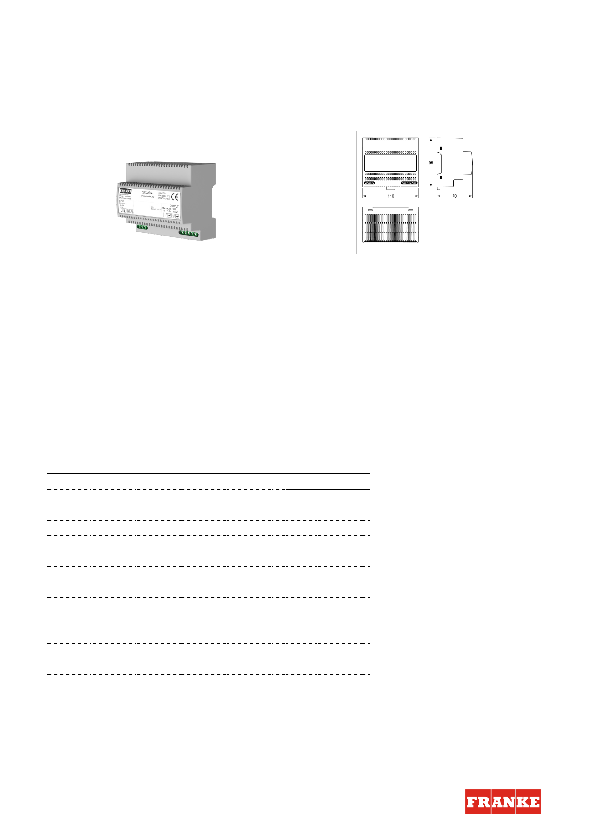
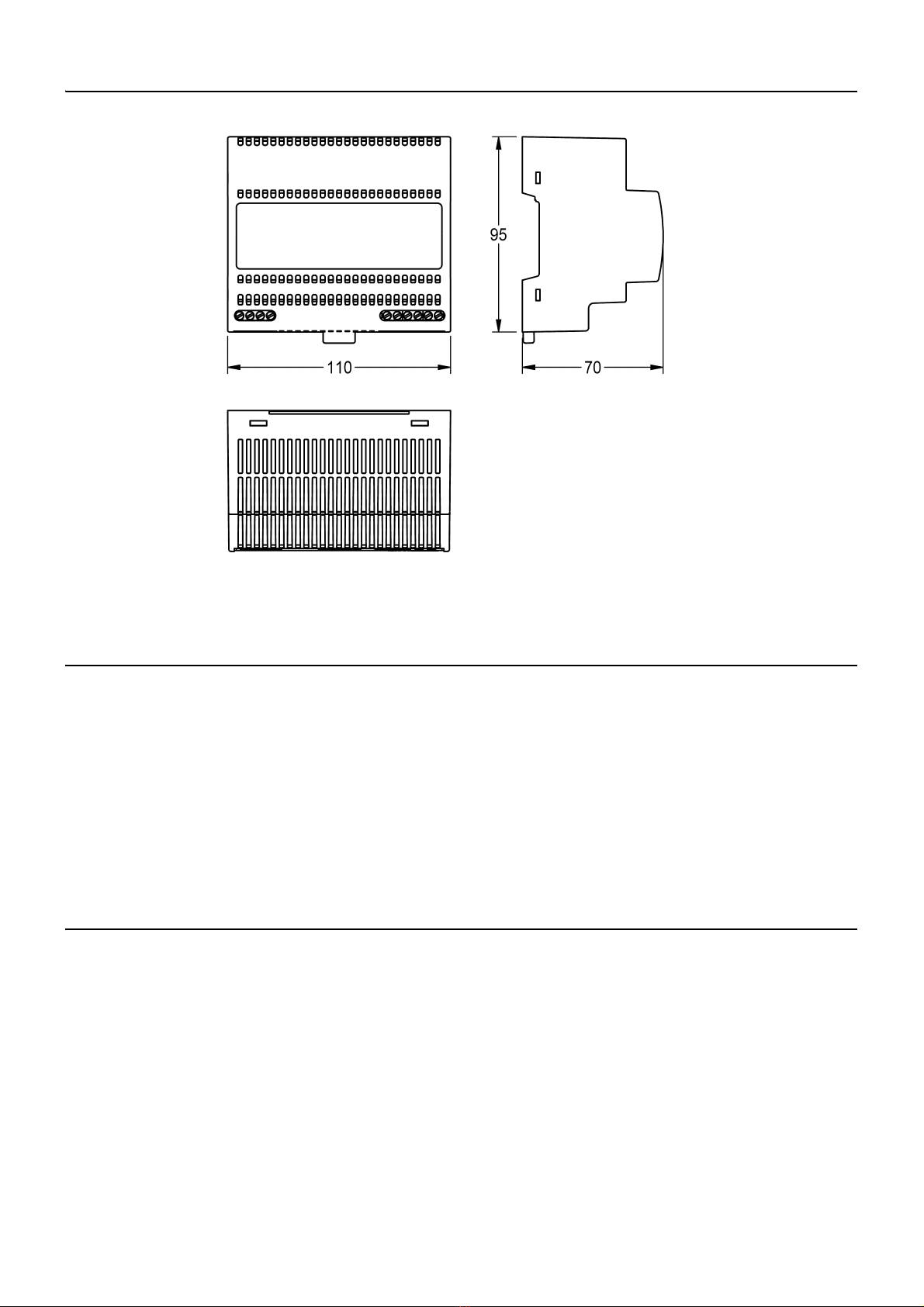
7. Maße . . . . . . . . . . . . . . . . . . . . . . . . . . . . . . . . . . . . . . . . . . . . . . 5
8. Lagerung . . . . . . . . . . . . . . . . . . . . . . . . . . . . . . . . . . . . . . . . . . . 5
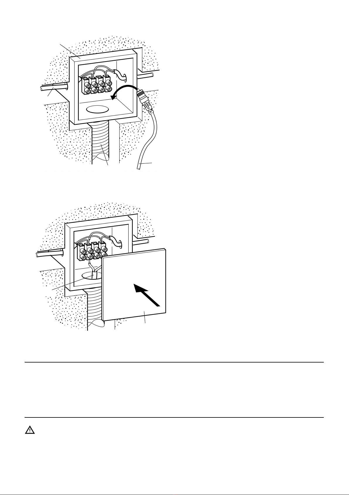
9. Wichtige Merkmale. . . . . . . . . . . . . . . . . . . . . . . . . . . . . . . . . . . . 5
10. Normen. . . . . . . . . . . . . . . . . . . . . . . . . . . . . . . . . . . . . . . . . . . . . 6
Montage, Funktion und Inbetriebnahme
11. Betriebshinweise . . . . . . . . . . . . . . . . . . . . . . . . . . . . . . . . . . . . . 6
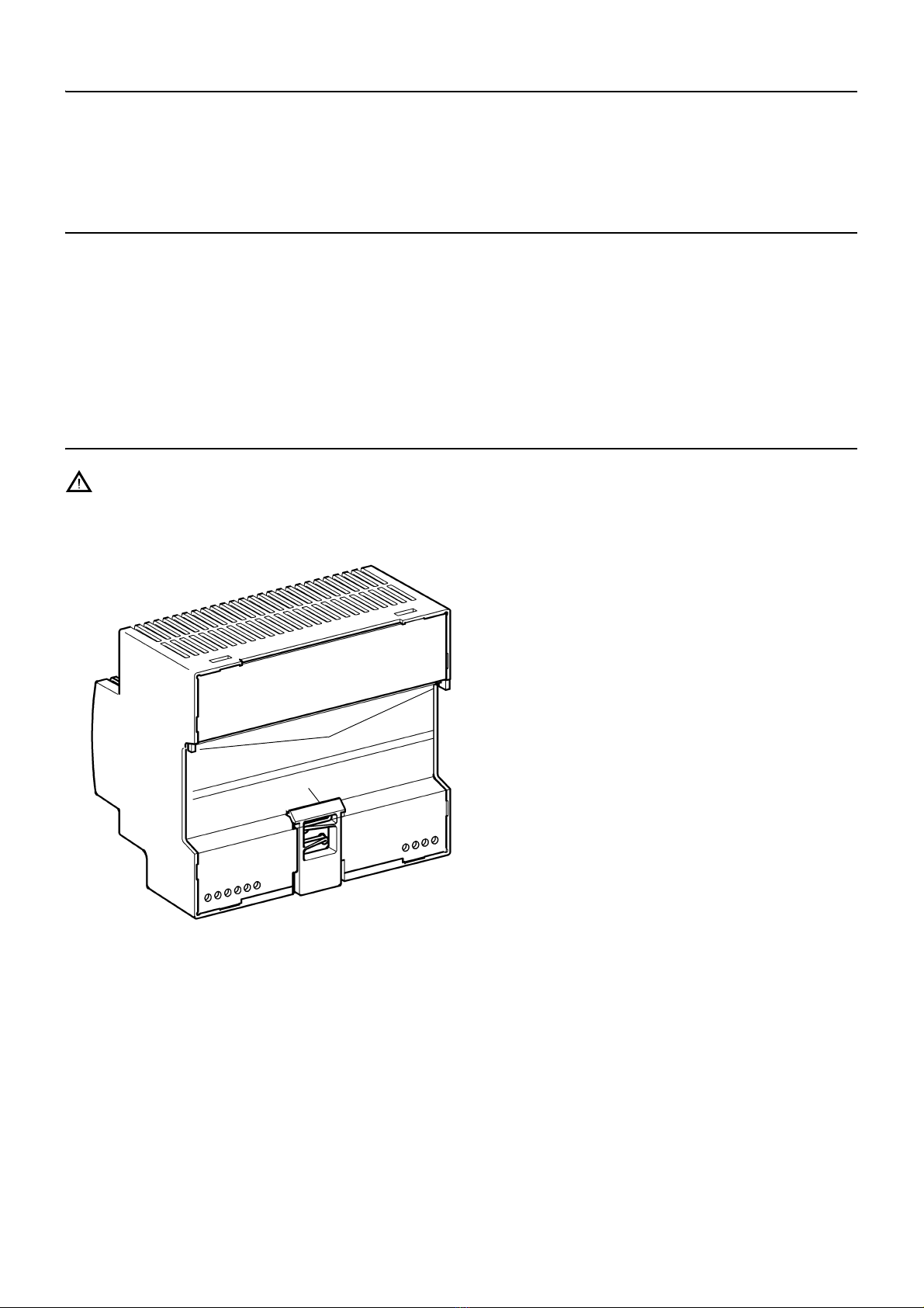
12. Montage/Demontage . . . . . . . . . . . . . . . . . . . . . . . . . . . . . . . . . . 6
13. Anschluss. . . . . . . . . . . . . . . . . . . . . . . . . . . . . . . . . . . . . . . . . . . 7
14. Kurzschluss- und Überlastverhalten. . . . . . . . . . . . . . . . . . . . . . . 8
13. Anschluss. . . . . . . . . . . . . . . . . . . . . . . . . . . . . . . . . . . . . . . . . . . 7
1. Abkürzungen und Einheiten
Uout Ausgangsspannung
L Außenleiter
N Nullleiter
RCD Residual Current Protective Device,
Fehlerstromschutzschalter
SELV Safety Extra Low Voltage, Schutzkleinspannung
EA-Nr. Europäische Artikelnummer
FAR-Best.-Nr. Franke Aquarotter-Bestellnummer
Umrechnung 1 mm = 0,03937 Zoll
1 Zoll = 25,4 mm
Alle Längenangaben in Grafiken sind in mm angegeben.

- 3 -
ZMI_001_2030039477-ACEX9001_#SDE_#AQU_#V1.fm
2. Zeichenerklärung
Warnung!
Nichtbeachtung kann Lebensgefahr oder Körperverletzung bewirken.
Achtung!
Nichtbeachtung kann Sachschäden bewirken.
☞Wichtig!
Nichtbeachtung kann Funktionsstörungen des Produkts bewirken.
☞Nützliche Information für den optimalen Umgang mit dem Produkt.
3. Gewährleistung
Haftung wird gemäß den allgemeinen Liefer- und Geschäftsbedingungen
übernommen.
Nur Original-Ersatzteile verwenden!
4. Wichtige Hinweise
• Montage, Inbetriebnahme und Wartung nur durch den Fachmann nach mitgelie-
ferter Anleitung entsprechend den gesetzlichen Vorschriften und den anerkannten
Regeln der Technik.
• Die technischen Anschlussbedingungen der örtlichen Wasser- und Energiever-
sorgungsunternehmen einhalten.
• Alle Arbeiten im spannungsfreien Zustand durchführen.
• Änderungen sind vorbehalten.
5. Anwendung
Netzteil nach EMV-Produktnorm und Sicherheit sowie EN60950 (SELV). Stabilisierte
Gleichstrom-Versorgung. Kunststoffgehäuse für Hutschienenmontage. Kurzschluss-
feste Ausführung, mit Federklemmen. Mit Sicherheitsabschaltung für
angeschlossene bistabile Magnetventile.
Maximale Kabellänge 10 m bei Kabelquerschnitt 0,32 qmm.

ZMI_001_2030039477-ACEX9001_#SDE_#AQU_#V1.fm
- 4 -
6. Technische Angaben
Normen/Zulassungen:
Sicherheit EN 60335-1
EN 60950-1
EN 61558-2-16
EMV EN 55022
EN 55024
EN 61000-3-2
EN 61000-3-3
EN 61000-6-2
EN 61000-6-3
EN 61204-3
RoHS
Eingang: 100-240 V ac / 50-60 Hz
Spannungsfreien: 85-264 V ac
Frequenz: 44 bis 66 Hz
Eingangsstrom: typ 1,05 A bei 230 V ac
Ausgang:
Anschlussspannung: 6,75-7,5 V / 12-14 V
Ausgangsseitig: 4 A
Argillite: < 150 mVpp (bei 20 MHz Bandbreite)
Schutzart: IP 20
Umgebungstemperatur: -25°C bis +55°C
Lagertemperatur: -40°C bis +85°C
Signalisierung LED: LED grün
Besonderheiten: Kurzschluss- und leerlauffest

- 5 -
ZMI_001_2030039477-ACEX9001_#SDE_#AQU_#V1.fm
7. Maße
8. Lagerung
9. Wichtige Merkmale
• Weitbereichs AC-Eingang ohne Umschaltung
• Schutzklasse 2
• primärseitig durch interne Sicherung geschützt
• Umschaltung zwischen 7 V und 12 V möglich.
• Montage für Hutschiene nach EN 50022
zulässige Lagerungstemperatur: -40 °C ... + 85 °C
zulässige Luftfeuchtigkeit: 30 ... 95 % relative Feuchte; bei Inbetrieb-
nahme darf keine Betauung vorliegen.
bei Langzeitlagerung: Betriebsmittel mit eingebauten Kondensatoren
sind mindestens alle 2 Jahre für mindestens
5 min an Netzspannung anzulegen

ZMI_001_2030039477-ACEX9001_#SDE_#AQU_#V1.fm
- 6 -
10. Normen
Die elektrische Sicherheit ist durch einen Geräteaufbau nach EN 60950 (VDE 0805)
gegeben. Es entspricht den Anforderungen und Normen zur CE-Konformität und
trägt das CE-Zeichen.
11. Betriebshinweise
Die Kühlung des Betriebsmittels darf nicht beeinträchtigt werden. Eine ungehinderte
Luftzufuhr und ein Mindestabstand von 15 mm zu benachbarten Teilen sind sicher-
zustellen.
Die Verdrahtung der Anschlussklemmen darf nur im spannungslosen Zustand
erfolgen. Aufgrund der Schutzart IP 20 ist der Betrieb des Gerätes nur in trockenen
Räumen zulässig.
12. Montage/Demontage
Achtung!
Das Systemnetzteil darf nur als SELV-Stromkreis betrieben werden. Das heißt, die
Systemleitung darf an keinem Punkt geerdet werden.
Montage auf Hutschienen
12.1
Das Netzteil oben (a) auf eine
Hutschiene 35 mm nach EN 50022
einhaken.
12.2
Das Netzteil unten gegen die
Hutschiene drücken, bis die Lasche
(b) einrastet.
☞Beim Anreihen von Modulen ist ein
Mindestabstand von 15 mm einzu-
halten.
Demontage von Hutschienen
12.3
Die Lasche (b) nach unten ziehen
und das Netzteil unten aushängen.
12.4
Das Netzteil nach oben abziehen
a
b

- 7 -
ZMI_001_2030039477-ACEX9001_#SDE_#AQU_#V1.fm
13. Anschluss
benötigte Materialien
Bauseits stellen:
• Feuchtraum-Verteilerdose (Ø 68 mm)
• Fehlerstromschutzschalter (RCD)
• Leerrohr für Anschlusskabel (Ø 10 mm)
• Leerrohr für Kabel
• 2-adriges Kabel
☞Die Stromversorgung außerhalb des Nassbereichs in einem extra Raum platzieren
und mit einem Fehlerstromschutzschalter (RCD) absichern.
13.1
Vorm Anschluss des Netzteiles die
zugehörige Betriebsspannung (siehe
Typenschild) prüfen.
13.2
Die Stromversorgung an die
Klemmen Input L und N (a)
anschließen.
13.3
Die Armaturen an die Klemmen
Output + und - (b) anschließen.
+ … rot
– … schwarz
Folgende Anschlusskabel verwenden:
Primärseitig (230 VAC):
Ausschließlich geeignete Installations-
kabel nach VDE (z. B. NYM 3×1,5 mm²)
verwenden.
Sekundärseitig (7 VDC/ 12 VDC):
Ausschließlich Original-Anschlusskabel
(FAR-Best.-Nr. 2030010982) verwenden.
Nur für 7 V:
Der Widerstand über die Gesamtlänge
des Kabels (vom Netzteil zur Armatur)
muss kleiner als 3,4 Ohm sein.
Der Querschnitt ist entsprechend der
Kabellänge zu wählen.
ab

ZMI_001_2030039477-ACEX9001_#SDE_#AQU_#V1.fm
- 8 -
14. Kurzschluss- und Überlastverhalten
Bei Kurzschluss im Netzbetrieb bleibt der Ausgang freigeschaltet. Die genannten
Spannungsschwellen für das Zu- und Abschalten gelten nach einem Kurzschluss
erst nach Spannungsfreischaltung auf der Primärseite oder Wiedererreichen der
Spannungsschwelle von 7 V.
15. Sicherungen
Achtung!
Das Netzteil ist intern primärseitig mit einer Sicherung 1,6 AT/250 V abgesichert.
Wenn diese Sicherung auslöst, liegt mit hoher Wahrscheinlichkeit ein Gerätedefekt
vor.
13.4
Je Armatur eine Feuchtraum-Vertei-
lerdose (c) installieren.
13.5
Ein Leerrohr (e; Ø 16 mm) von der
Feuchtraum-Verteilerdose zum
Wandeinbaukasten verlegen.
13.6
Ein flexibles 2-adriges Kabel (d) im
Leerrohr verlegen und von
Feuchtraum-Verteilerdose zu
Feuchtraum-Verteilerdose schieben.
13.7
Das Anschlusskabel (f) für den
Sensor durch das Leerrohr (e)
schieben.
☞Der Stecker muss im Wandeinbau-
kasten gut zugänglich sein.
13.8
Das Anschlusskabel (f) für den
Sensor in der Feuchtraum-Vertei-
lerdose anschließen.
13.9
DieFeuchtraum-Verteilerdosemitder
Schutzkappe (g) verschließen.
c
d
ef
f
g

- 9 -
ZMI_001_2030039477-ACEX9001_#SDE_#AQU_#V1.fm
16. Anschlussbeispiel (nur für 7 V)
☞Die maximale Kabellänge und Armaturenanzahl hängt von der Installationsart und
des Kabelquerschnitts ab.
16.1 Installationsbeispiel Linien-Struktur
A: max. Kabellänge siehe Tabelle
B: Netzteil
230 V AC
Q: Querschnitt in mm2
0,5 0,75 11,5 2,5
N: Anzahl der Armaturen
140 m 60 m 80 m 120 m 200 m
220 m 30 m 40 m 60 m 100 m
314 m 20 m 25 m 40 m 70 m
410 m 15 m 20 m 30 m 50 m
58 m 12 m 15 m 25 m 40 m
67 m 10 m 14 m 22 m 35 m
75 m 8 m 12 m 19 m 31 m
85 m 8 m 11 m 16 m 27 m
95 m 7 m 10 m 12 m 20 m
10 4 m 6 m 8 m 12 m 20 m
11 4 m 6 m 8 m 12 m 20 m
12 4 m 5 m 7 m 11 m 18 m
13 3 m 5 m 7 m 10 m 17 m
14 3m5m6m9m16m
15 3m4m6m9m15m
16 2m4m5m8m14m

ZMI_001_2030039477-ACEX9001_#SDE_#AQU_#V1.fm
- 10 -
16.2 Installationsbeispiel Sternform
B: Netzteil
max. 12 Armaturen
230 V AC
A: max. Kabellänge
siehe Tabelle
L: maximale Kabellänge in m
Q: Querschnitt in mm2
0,25 20
0,5 40
0,75 60
180
1,5 120
2,5 200

- 11 -
ZMI_001_2030039477-ACEX9001_#SDE_#AQU_#V1.fm
Notizen

Australia
PR Kitchen and Water Systems Pty Ltd
Dandenong South VIC 3175
Phone +61 3 9700 9100
Austria
Franke GmbH
6971 Hard
Phone +43 5574 6735 0
Belgium & Luxembourg
Franke N.V.
9400 Ninove, Belgium
Phone +32 54 310 130
Czech Republic
Franke Aquarotter GmbH
14974 Ludwigsfelde, Germany
Phone +420 281 090 429
France
Franke GmbH
6971 Hard, Austria
Phone +33 800 909 216
Germany
Franke Aquarotter GmbH
14974 Ludwigsfelde
Phone +49 3378 818 530
Italy
Franke Water Systems AG
4663 Aarburg, Switzerland
Numero Verde 800 789 233
Middle East
Franke LLC
Ras Al Khaimah, United Arab Emirates
Phone +971 7 2034 700
Morocco
Franke Kitchen System SARL
21 000 Casablanca
Phone +212 522 674 200
Netherlands
Franke N.V.
9400 Ninove, Belgium
Phone +31 492 72 82 24
Poland
Franke Aquarotter GmbH
14974 Ludwigsfelde, Germany
Phone +48 22 711 6717
Portugal
Franke Portugal S.A.
2735-531 Cacém
Phone +351 21 426 9670
South Africa & Sub Saharan Africa
Franke South Africa
Durban, 4052
Phone + 27 31 450 6300
Spain
Franke GmbH
6971 Hard, Austria
Phone +43 5574 6735 211
Switzerland & Liechtenstein
Franke Water Systems AG
4663 Aarburg
Phone +41 62 787 3131
Turkey
Franke Mutfak ve Banyo Sistemleri
Sanayi ve Ticaret A.S.
41400 Gebze Kocaeli
Phone +90 262 644 6595
United Kingdom
Franke Sissons Ltd.
Barlborough S43 4PZ
Phone +44 1246 450 255
Dart Valley Systems Ltd.
Paignton TQ4 7TW
Phone +44 1803 529 021
EAST EUROPE
Bosnia Herzegovina | Bulgaria |
Croatia | Hungary | Latvia | Lithuania |
Romania | Russia | Serbia | Slovakia |
Slovenia | Ukraine
Franke Aquarotter GmbH
14974 Ludwigsfelde, Germany
Phone +49 3378 818 530
NORTH AMERICA
United States | Canada
Franke Kindred Canada Limited
Midland, ON L4R 4K9, Canada
Phone +1 855 446 5663
SCANDINAVIA & ESTONIA
Finland | Sweden | Norway |
Denmark | Estonia
Franke Finland Oy
76850 Naarajärvi, Finland
Phone +358 15 34 111
OTHER COUNTRIES
Franke GmbH
6971 Hard, Austria
Phone +43 5574 6735 0
www.franke.com
© Franke Technology and Trademark Ltd., Switzerland / 26.07.17 / 2030039569

Installation and operating instructions Montażi instrukcja obsługi
Notice de montage et de mise en service Monterings- og driftsvejledning
Instrucciones de montaje y uso Návod pro montáž a provoz
Istruzioni per il montaggio e l’uso Asennus- ja käyttöohje
Montage- en bedrijfsinstructies Инструкция по монтажу ивводу в
эксплуатацию
ZMI_001_2030039477-ACEX9001_#SALL_#AQU_#V1.fm / 26.07.17
EA-Nr.: 7612982244193
FAR-Best.-Nr.: 2030039477
ACEX9001
DE
EN
FR
ES
IT
NL
PL
SV
CS
FI
RU

2
Inhaltsverzeichnis35.fm
...................................................................................3
Please refer to the graphics in the German Installation and
Operating Instructions.
...................................................................................10
Les graphiques sont disponibles dans la notice de montage et
de mise en service allemande.
...................................................................................17
Por favor, consulte los gráficos en las instrucciones alemanas
de montaje y uso.
...................................................................................24
Per le grafiche fare riferimento alle Istruzioni per il montaggio
e l’uso in tedesco.
...................................................................................31
De tekeningen kunt u in de Duitse montage- en bedrijfsinst-
ructies vinden.
...................................................................................38
Prosimy przyjąć grafikęz niemieckiej instrukcji montażu i
obsługi.
...................................................................................45
Bilderna finns i den tyska monterings- och bruksanvisningen.
...................................................................................52
Obrázky najdete v nìmeckém návodu k montáži a obsluze.
...................................................................................59
Kuvat löydätte saksankielisestä asennus- ja käyttöohjeesta.
...................................................................................66
Рисунки приведены винструкции по монтажу и
эксплуатации на немецком языке.
EN
FR
ES
IT
NL
PL
SV
CS
FI
RU

- 3 -
ZMI_001_2030039477-ACEX9001_#SEN_#AQU_#V1.fm
0English
Power Supply
Please refer to the graphics in the German Installation and Operating Instructions.
0Table of Contents
1. Abbreviations and Units . . . . . . . . . . . . . . . . . . . . . . . . . . . . . . . . 4
2. Key . . . . . . . . . . . . . . . . . . . . . . . . . . . . . . . . . . . . . . . . . . . . . . . . 4
3. Warranty . . . . . . . . . . . . . . . . . . . . . . . . . . . . . . . . . . . . . . . . . . . . 4
4. Important Notes . . . . . . . . . . . . . . . . . . . . . . . . . . . . . . . . . . . . . . 4
Description of Product
5. 5. Application . . . . . . . . . . . . . . . . . . . . . . . . . . . . . . . . . . . . . . . . 5
6. Technical Specifications . . . . . . . . . . . . . . . . . . . . . . . . . . . . . . . . 5
7. Dimensions. . . . . . . . . . . . . . . . . . . . . . . . . . . . . . . . . . . . . . . . . . 5
8. Storage . . . . . . . . . . . . . . . . . . . . . . . . . . . . . . . . . . . . . . . . . . . . . 6
9. Most Important Features . . . . . . . . . . . . . . . . . . . . . . . . . . . . . . . 6
10. Standards . . . . . . . . . . . . . . . . . . . . . . . . . . . . . . . . . . . . . . . . . . . 6
Installation, Function and Commissioning
11. Notes on Operation . . . . . . . . . . . . . . . . . . . . . . . . . . . . . . . . . . . 6
12. Installing/Removing . . . . . . . . . . . . . . . . . . . . . . . . . . . . . . . . . . . 7
13. Connection . . . . . . . . . . . . . . . . . . . . . . . . . . . . . . . . . . . . . . . . . . 7
14. Short Circuit and Overload Behaviour . . . . . . . . . . . . . . . . . . . . . 8
15. Fuses . . . . . . . . . . . . . . . . . . . . . . . . . . . . . . . . . . . . . . . . . . . . . . 8
16. Connection Example (only for 7 V). . . . . . . . . . . . . . . . . . . . . . . . 9
EN
EN

ZMI_001_2030039477-ACEX9001_#SEN_#AQU_#V1.fm
- 4 -
1. Abbreviations and Units
2. Key
Warning!
Failure to observe can result in injury or even death.
Caution!
Failure to observe can cause the product to malfunction.
☞Important!
Failure to observe can cause the product to malfunction.
☞Useful information for optimally handling the product.
3. Warranty
Liability is accepted according to the General Terms and Conditions of Business and
Supply.
Use original replacement parts only!
4. Important Notes
• Installation, commissioning and maintenance are to be performed only by a
qualified technician according to the instructions provided and in accordance with
legal requirements and acknowledged rules of technology.
• All technical connection regulations specified by the local water and electricity
supply utility companies must be complied with.
• All work must be carried out in a de-energised state.
• All rights reserved to make technical alterations.
Uout Output voltage
L Phase conductor
N Earth wire
RCD Residual Current Protective Device,
Earth leakage circuit breaker
SELV Safety Extra Low Voltage
EA-Nr. European Article Number
FAR-Best.-Nr. Franke Aquarotter Order Number
Conversion 1 mm = 0.03937 inches
1 inches = 25,4 mm
All length specifications in the graphics are in mm.

- 5 -
ZMI_001_2030039477-ACEX9001_#SEN_#AQU_#V1.fm
5. 5. Application
Power supply in compliance with EMC product standard and Safety. Stabilized DC
power supply. Plastic housing for DIN rail mounting. Short-circuit-proof design, with
spring terminals. With safety shut-down for connected bistable solenoid valves.
Maximum cable length 10 m with cable cross section 0.32 mm²
6. Technical Specifications
7. Dimensions
Standards / Approvals
Safety EN 60335-1
EN 60950-1
EN 61558-2-16
EMC EN 55022
EN 55024
EN 61000-3-2
EN 61000-3-3
EN 61000-6-2
EN 61000-6-3
EN 61204-3
RoHS
Input: 100-240 V ac / 50-60 Hz
Voltage range: 85-264 V ac
Frequency: 44 to 66 Hz
Input current: typ 1.05 A at 230 V AC
Output:
Output voltage: 6,75-7.5 V / 12-14 V
Output current: 4 A
Ripple: < 150 mVpp (at 20 MHz bandwidth)
Type of protection: IP 20
Ambient temperature: -25°C to +55°C
Storage temperature: -40°C to +85°C
LED signalling: Green LED
Special features: Short-circuit proof and open-circuit proof

ZMI_001_2030039477-ACEX9001_#SEN_#AQU_#V1.fm
- 6 -
8. Storage
9. Most Important Features
• Wide-range AC input without switching
• Protection class 2
• Primary side protected by internal circuit breaker
• 7 V and 12 V output voltage can be selected.
• Mounting for DIN rail according to EN 50022
10. Standards
Electrical safety is provided by means of a design in compliance with EN 60950
(VDE 0805). It meets the requirements and standards required for CE conformity
and carries the CE symbol.
11. Notes on Operation
Appliance cooling must not be impaired. In order to ensure an unimpeded flow of air,
a minimum distance of 15 mm to adjacent parts must be maintained.
Wiring connections to the connector terminals must only be made in an electrically
dead condition. Due to the type of protection used (IP 20), the device must be
operated in dry rooms only.
permissible storage temperature: -40 °C ... + 85 °C
Permissible humidity: 30 ... 95 % relative humidity; there must be
no condensation present when the system is
started up.
bei Langzeitlagerung: With long-term storage: Appliances with
built-in capacitors must be connected to
mains voltage for at least 5 minutes every
2years.

- 7 -
ZMI_001_2030039477-ACEX9001_#SEN_#AQU_#V1.fm
12. Installing/Removing
Caution!
The system power supply must be operated only as a SELV circuit. This means that
the system line must not be earthed at any point.
Installation on DIN Mounting Rails
12.1
Hook the power supply into a (a) 35 mm DIN rail (top side) in compliance with
EN 50022.
12.2
Press the power supply (bottom side) into the DIN rail until the tab (b) snaps into
place.
☞When lining up several modules on the rail, maintain a minimum spacing of 15 mm.
Removal from DIN Mounting Rails
12.3
Pull the tab (b) downwards and unhook the power supply (bottom side).
12.4
Pull off the power supply upwards.
13. Connection
Materials Required
To be provided by the customer:
• Moisture-proof junction box (Ø 68 mm)
• Earth leakage circuit breaker (RCD)
• Empty conduit for connecting cables (Ø 10 mm)
• Empty conduit for cables
• 2-wire cable
☞Position the power supply outside of the wet area, in a separate room, and protect it
with an earth leakage circuit breaker (RCD).
13.1
Before connecting the power supply, check that the correct voltage is available (see
type plate).
13.2
Connect the power supply to input terminals L and N (a).
13.3
Connect the fittings to output terminals + and - (b).
+ … red
– … black
Table of contents
Languages:
Other Franke Power Supply manuals