Franke ZAQUA006 User manual

Installation and operating instructions Istruzioni per il montaggio e l’uso
Notice de montage et de mise en service Montage- en bedrijfsinstructies
ZMI_001_2000100977-ZAQUA006_#SALL_#AQU_#V1.fm/13.10.14
Franke Aquarotter GmbH, Germany
EA-Nr.: 7612982079283
FAR-Best.-Nr.: 2000100977
ZAQUA006
DE
EN
FR
IT
NL

2
Inhaltsverzeichnis.fm
.........................................................3
Please refer to the graphics in the German Instal-
lation and Operating Instructions.
.........................................................8
Les graphiques sont disponibles dans la notice de
montage et de mise en service allemande.
.........................................................13
Per le grafiche fare riferimento alle Istruzioni per il
montaggio e l’uso in tedesco.
.........................................................18
De tekeningen kunt u in de Duitse montage- en
bedrijfsinstructies vinden.
EN
FR
IT
NL

3
ZMI_001_2000100977-ZAQUA006_#SEN_#AQU_#V1.fm
0English
A3000 open Uninterruptible Power Supply, 24 V DC / 3.2 Ah
Please refer to the graphics in the German Installation and Operating Instructions.
0Table of Contents
1. Abbreviations and Terminology . . . . . . . . . . . . . . . . . . . . . . . . . . 3
2. Key . . . . . . . . . . . . . . . . . . . . . . . . . . . . . . . . . . . . . . . . . . . . . . . . 4
3. Warranty. . . . . . . . . . . . . . . . . . . . . . . . . . . . . . . . . . . . . . . . . . . . 4
4. Important Notes . . . . . . . . . . . . . . . . . . . . . . . . . . . . . . . . . . . . . . 4
Product Description
5. Application . . . . . . . . . . . . . . . . . . . . . . . . . . . . . . . . . . . . . . . . . . 4
6. Technical Specifications . . . . . . . . . . . . . . . . . . . . . . . . . . . . . . . . 5
7. Special Features. . . . . . . . . . . . . . . . . . . . . . . . . . . . . . . . . . . . . . 6
8. Dimensions. . . . . . . . . . . . . . . . . . . . . . . . . . . . . . . . . . . . . . . . . . 6
Installation, Function and Commissioning
9. Functional Description . . . . . . . . . . . . . . . . . . . . . . . . . . . . . . . . . 6
10. Assembly Instructions. . . . . . . . . . . . . . . . . . . . . . . . . . . . . . . . . . 7
11. LED status indicator . . . . . . . . . . . . . . . . . . . . . . . . . . . . . . . . . . . 7
1. Abbreviations and Terminology
EA-Nr. European article number
FAR-Best.-Nr. Franke-Aquarotter Order No.
Conversion 1 mm = 0.03937 inches
1 inch = 25.4 mm
All length specifications in the graphics are in mm.
EN

4
ZMI_001_2000100977-ZAQUA006_#SEN_#AQU_#V1.fm
2. Key
Warning!
Failure to observe can cause mortal danger or bodily injury.
Important!
Failure to observe can cause material damages.
☞Important!
Failure to observe can cause the product to malfunction.
☞Useful information for optimally handling the product.
3. Warranty
Liability is accepted according to the General Terms and Conditions of Business and
Supply.
Only use original replacement parts!
4. Important Notes
• Installation, commissioning and maintenance are to be performed only by a
qualified technician according to the instructions provided and in accordance with
legal requirements and acknowledged rules of technology.
• All technical connection regulations specified by the local water and electricity
supply utility companies must be complied with.
• All rights reserved to make technical alterations.
5. Application
A3000 open uninterruptible power supply for connecting to an ECC function
controller, as an emergency power supply in the event that the 230 V AC primary
power supply fails. Maintains operability of system up to 60 minutes, depending on
load. With integrated charge control and maintenance-free 24 V DC / 3.2 Ah lead-
gel accumulator module.

5
ZMI_001_2000100977-ZAQUA006_#SEN_#AQU_#V1.fm
6. Technical Specifications
☞The pin assignment for charging operation and UPS operation is the same.
Product group: Uninterruptible power supply 24 V DC/2.5 A
capacity 3.2–3.5 Ah Pb
EMC: EN 61000-6-3 (unwanted emission)
EN 61000-6-2 (interference immunity)
Type of protection IP 20
Protection class: III
Test voltage: 4.2 kV DC
Ambient temperature: 0 to +40 °C
Cooling: Natural convection
Humidity: 30 to 80 % relative humidity
There must be no dew formation when the system
is to be commissioned.
Storage temperature: -20 to +40 °C
Long-term storage: To maintain the condensers, apply mains voltage
to the device for at least 5 min. every two years.
Input
Input DC: 24.5 V DC
Range 24.5–30 V DC
Rated current: Max. 0.5 A charging current
Connections: WAGO series 734 multiplug-system for
max. 1.5 mm²
Output
Protected load circuit
voltage during battery
operation:
24.0–19.2 V DC and 2.5 A
Rated voltage: 24 V DC
Range: 0–24.0 V DC (preset to 24.0 V DC)
Current: 2.5 at 19.2–24.0 V DC
Current limitation: By means of an externally accessible 2.5 AT safety
fuse, overload protection by means of current
limitation when battery undervoltage is <18.0 V DC
Connections: WAGO series 734 multiplug-system for
max. 1.5 mm²

6
ZMI_001_2000100977-ZAQUA006_#SEN_#AQU_#V1.fm
7. Special Features
• Can be connected in parallel to increase ready time
• Conditionally short-circuit proof due to 2.5 A fuse
• Open-circuit proof
• Temperature-compensated charging circuit for optimum battery life
• Life of battery according to manufacturer: 4–6 years at 20 °C
• approx. 60 min UPS operation at 1.9 A according to battery data sheet
8. Dimensions
9. Functional Description
The 24 V DC UPS unit with integrated maintenance-free lead-gel cell battery
features the following functions:
• I/U charger featuring PWM-power-stage and internal temperature-tracking
• Battery charging voltage 28.8 V DC nominal value at 25 °C
• Charge conservation at 27.6 V DC nominal value at 25 °C
• Low-discharge protection with concurrent reduced current limitation from 19.2 V
• Short-circuit protection by means of externally accessible 2.5 AT (5×20) miniature
fuse
• Status and condition display with 4 LEDs on the front side
• No additional self-discharge by means of externally disconnectable charging and
control unit
• Directly connectable to the 24 V DC power supply
• Uninterruptible continuation of the 24 V DC UPS voltage in the event of mains
failure
• Disconnectable unit on the underside of the housing, for reliable commissioning
and providing discharge protection during interim storage
• Mounting device for mounting on a wall and/or on a TS-35 top-hat rail
• Turn on the device by means of the switch on the underside of the housing

7
ZMI_001_2000100977-ZAQUA006_#SEN_#AQU_#V1.fm
10. Assembly Instructions
☞When installing several devices, to ensure an unimpeded flow of cooling air, it is
important to provide a minimum distance of 15 mm to neighbouring parts.
Mounting on and dismounting from top-hat rails TS 35
10.1
For mounting, insert the device with the top-hat rail guide into the lower edge of the
top-hat rail and tilt it upwards to make it lock in position.
10.2
To dismount, lift the device in order to overcome the spring force, and then tilt it
down to unlock it.
Installing on a wall
10.3
Mark the holes for the 4 screws.
10.4
Drill according to the markings.
☞Depending on the composition of the wall, special wall dowels may have to be used
(not included).
10.5
Insert the dowels.
10.6
Use 4 screws in the tabs to mount the device to the wall.
11. LED status indicator
LED Meaning
orange – UPS mode
– External power supply voltage:< 24 V DC
red – UPS voltage < 19.2 V in UPS mode
– Battery voltage < 26.5 V after first commissioning,
or after UPS mode when UPS voltage was
< 19.2 V
yellow – Batteries are being charged
green – Battery voltage > 26.5 V during normal mode
– UPS voltage > 19.2 V during UPS mode, when the
battery voltage prior to UPS mode was > 26.5 V
– External power supply (24.5-30 V DC) present
when UPS unit is switched off

8
ZMI_001_2000100977-ZAQUA006_#SFR_#AQU_#V1.fm
0Français
Alimentation électrique ininterrompue A3000 open, 24 V DC / 3,2 Ah
Les graphiques sont disponibles dans la notice de montage et de mise en service
allemande.
0Table des matières
1. Abréviations et unités. . . . . . . . . . . . . . . . . . . . . . . . . . . . . . . . . . 8
2. Explication des symboles. . . . . . . . . . . . . . . . . . . . . . . . . . . . . . . 9
3. Garantie . . . . . . . . . . . . . . . . . . . . . . . . . . . . . . . . . . . . . . . . . . . . 9
4. Remarques importantes. . . . . . . . . . . . . . . . . . . . . . . . . . . . . . . . 9
Description du produit
5. Application . . . . . . . . . . . . . . . . . . . . . . . . . . . . . . . . . . . . . . . . . . 9
6. Données techniques. . . . . . . . . . . . . . . . . . . . . . . . . . . . . . . . . . . 10
7. Caractéristiques principales . . . . . . . . . . . . . . . . . . . . . . . . . . . . . 11
8. Dimensions. . . . . . . . . . . . . . . . . . . . . . . . . . . . . . . . . . . . . . . . . . 11
Montage, fonctionnement et mise en service
9. Description du fonctionnement. . . . . . . . . . . . . . . . . . . . . . . . . . . 11
10. Montage . . . . . . . . . . . . . . . . . . . . . . . . . . . . . . . . . . . . . . . . . . . . 12
11. Affichage d’état par DEL. . . . . . . . . . . . . . . . . . . . . . . . . . . . . . . . 12
1. Abréviations et unités
EA-Nr. Référence européenne
FAR-Best.-Nr. Numéro de commande Franke-Aquarotter
Conversion 1 mm = 0,03937 pouce
1 pouce = 25,4 mm
Les longueurs sont toujours indiquées en mm dans les graphiques.
FR

9
ZMI_001_2000100977-ZAQUA006_#SFR_#AQU_#V1.fm
2. Explication des symboles
Avertissement !
Le non respect des consignes peut entraîner un danger mortel ou des blessures
corporelles.
Attention !
Le non respect des consignes peut entraîner des dommages matériels.
☞Important !
Le non respect des consignes peut entraîner des dysfonctionnements du produit.
☞Informations utiles pour l’utilisation optimale du produit.
3. Garantie
La responsabilité est conforme à celle décrite dans les conditions générales de
vente et de livraison.
Utiliser exclusivement des pièces de rechange d’origine !
4. Remarques importantes
• Seul un spécialiste est habilité à effectuer le montage, la mise en service et
l’entretien de l’installation, en conformité aux instructions du manuel livré, aux
règlements légaux en vigueur et aux règles techniques en usage.
• Observer les conditions techniques de raccordement des entreprises locales de
distribution d’eau et d’énergie.
• Sous réserve de modifications.
5. Application
Alimentation électrique ininterrompue A3000 open pour le raccordement au
contrôleur de fonctionnement ECC comme pontage en cas de panne secteur de la
tension d’alimentation primaire 230 VAC. Maintien du fonctionnement jusqu’à 60
minutes en fonction de l’utilisation de l’installation. Avec régulation de charge
intégrée et module d’accumulateurs sans plomb et sans entretien 24 V DC / 3,2 Ah.

10
ZMI_001_2000100977-ZAQUA006_#SFR_#AQU_#V1.fm
6. Données techniques
☞L’affectation des contacts est la même en mode chargement et en mode ASI.
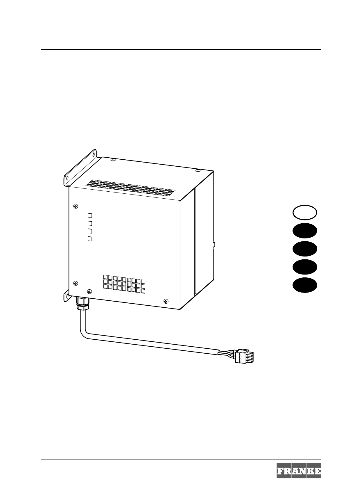
Groupe de produit : Alimentation électrique ininterrompue 24 V DC/
2,5 A capacité 3,2–3,5 Ah Pb
CEM : EN 61000-6-3 (émissions perturbatrices)
EN 61000-6-2 (résistance aux interférences)
Type de protection IP 20
Classe de protection : III
Tension de contrôle : 4,2 kV DC
Température ambiante : De 0 à +40 °C
Refroidissement : Convection naturelle
Humidité de l’air : 30 à 80 % d’humidité relative
Pas de rosée lors de la mise en service.
Température de stockage : De -20 à +40 °C
Stockage prolongé : Pour le maintien des condensateurs sur l’appareil,
appliquer une tension réseau pendant 5 min. au
moins tous les deux ans.
Entrée
Entrée CC : 24,5 V DC
Plage 24,5–30 V DC
Courant de référence : Max. 0,5 A courant de charge
Raccordements : Système multifiches WAGO série 734 pour
max. 1,5 mm²
Sortie
Tension du circuit de
charge protégée en mode
batterie :
24,0–19,2 V DC et 2,5 A
Tension de référence : 24 V DC
Plage : 0–24,0 V DC (préréglée sur 24,0 V DC)
Courant : 2,5 à 19,2–24,0 V DC
Limitation de courant : Par un fusible accessible depuis l’extérieur 2,5 AT
protection contre les surcharges par limitation du
courant avec une sous-tension de batterie
<18,0 V DC
Raccordements : Système multifiches WAGO série 734 pour
max. 1,5 mm²

11
ZMI_001_2000100977-ZAQUA006_#SFR_#AQU_#V1.fm
7. Caractéristiques principales
• Branchement en parallèle possible pour améliorer la disponibilité
• Résistance partielle aux courts-circuits par fusible 2,5 A
• Résiste à la marche à vide
• Commutation de charge à compensation de température pour une durée de vie
optimale des accumulateurs
• Durée de vie indiquée sur les accumulateurs conformément aux indications du
fabricant 4–6 ans à 20 °C
• Emv. 60 min mode ASI à 1,9 A conformément à la fiche technique des accumula-
teurs
8. Dimensions
9. Description du fonctionnement
L’unité ASI 24 V DC avec accumulateurs au gel de plomb sans entretien comprend
les fonctions suivantes :
• Charge I/U avec niveau de charge PWM et ajustement interne de température
• Tension de charge de la batterie 28,8 V DC valeur nominale à 25 °C
• Conservation de charge à 27,6 V DC valeur nominale à 25 °C
• Protection contre la décharge partielle avec limitation de courant réduite simul-
tanée à partir de 19,2 V
• Protection contre les courts-circuits par fusible précis accessible de l'extérieur
2,5 AT (5×20)
• Affichage de l’état et du statut par 4 DEL sur la face avant
• Pas de décharge spontanée grâce à une unité de contrôle et de charge extérieure
pouvant être désactivée
• Raccordement direct avec l’alimentation électrique 24 V DC
• Reprise sans interruption de la tension ASI 24 V DC en cas de panne de secteur
• Possibilité de désactiver l’unité sur la face inférieure du boîtier pour une mise en
service sûre et comme protection de décharge lors du stockage intermédiaire
• Dispositif de montage pour la fixation murale et sur rail porteur TS-35
• Mettre en marche l'appareil sur la face inférieure du boîtier

12
ZMI_001_2000100977-ZAQUA006_#SFR_#AQU_#V1.fm
10. Montage
☞Lors du montage de plusieurs appareils, veiller à ce que l’amenée d’air ne soit pas
bouchée et respecter un écart minimal de 15 mm avec les pièces jouxtant l’appareil.
Montage et démontage sur rails porteurs TS 35
10.1
Pour le montage, placer l’appareil avec le guidage rails porteurs dans l’arête
inférieure du rail porteur et basculer vers le haut ou le bas pour réaliser l’enclen-
chement.
10.2
Pour le démontage, soulever l’appareil pour vaincre la force du ressort et déver-
rouiller en le basculant vers le bas.
Montage mural
10.3
Marquer les alésages pour les 4 vis.
10.4
Percer selon les marquages.
☞En fonction de la structure du mur, il peut être nécessaire d'utiliser des chevilles
spéciales (non comprises dans la livraison).
10.5
Insérer les chevilles.
10.6
Avec 4 vis, fixer l’appareil aux attaches de fixation sur le mur.
11. Affichage d’état par DEL
DEL Signification
Orange – MODE ASI
– Tension d’alimentation extérieure < 24 V DC
Rouge – Tension ASI < 19,2 V en mode ASI
– Tension des accumulateurs < 26,5 V après la
première mise en service ou après le mode ASI
lorsque la tension ASI était < 19,2 V
Jaune – Chargement des accumulateurs
Vert – Tension des accumulateurs > 26,5 V en mode
normal
– Tension ASI > 19,2 V en mode ASI lorsque la
tension des accumulateurs était > 26,5 V avant le
mode ASI
– Alimentation en tension ext. (24,5-30 V DC)
présente lorsque l’unité ASI est désactivée

13
ZMI_001_2000100977-ZAQUA006_#SIT_#AQU_#V1.fm
0Italiano
Alimentazione continua A3000 open, 24 V DC / 3,2 Ah
Per le grafiche fare riferimento alle istruzioni per il montaggio e l’uso in tedesco.
0Sommario
1. Abbreviazioni e unità . . . . . . . . . . . . . . . . . . . . . . . . . . . . . . . . . . 13
2. Spiegazione dei simboli . . . . . . . . . . . . . . . . . . . . . . . . . . . . . . . . 14
3. Garanzia. . . . . . . . . . . . . . . . . . . . . . . . . . . . . . . . . . . . . . . . . . . . 14
4. Avvertenze importanti. . . . . . . . . . . . . . . . . . . . . . . . . . . . . . . . . . 14
Descrizione del prodotto
5. Uso. . . . . . . . . . . . . . . . . . . . . . . . . . . . . . . . . . . . . . . . . . . . . . . . 14
6. Specifiche tecniche. . . . . . . . . . . . . . . . . . . . . . . . . . . . . . . . . . . . 15
7. Caratteristiche specifiche del prodotto . . . . . . . . . . . . . . . . . . . . . 16
8. Dimensioni . . . . . . . . . . . . . . . . . . . . . . . . . . . . . . . . . . . . . . . . . . 16
Montaggio, funzionamento e messa in esercizio
9. Descrizione del funzionamento . . . . . . . . . . . . . . . . . . . . . . . . . . 16
10. Montaggio. . . . . . . . . . . . . . . . . . . . . . . . . . . . . . . . . . . . . . . . . . . 17
11. LED di indicazione dello stato . . . . . . . . . . . . . . . . . . . . . . . . . . . 17
1. Abbreviazioni e unità
EA-Nr. Codice articolo europeo
FAR-Best.-Nr. Numero d'ordine Franke-Aquarotter
Fattore di conversione 1 mm = 0,03937 pollici
1 pollice = 25,4 mm
Tutte le quote nelle grafiche sono espresse in millimetri.
IT

14
ZMI_001_2000100977-ZAQUA006_#SIT_#AQU_#V1.fm
2. Spiegazione dei simboli
Avvertenza!
La non osservanza può causare pericolo per la vita o lesioni corporee.
Attenzione!
La non osservanza può causare danni materiali.
☞Importante!
La non osservanza può causare malfunzionamenti del prodotto.
☞Informazioni utili per l’uso ottimale del prodotto.
3. Garanzia
La garanzia viene accordata conformemente alle nostre condizioni generali di
vendita e consegna.
Utilizzare esclusivamente pezzi di ricambio originali!
4. Avvertenze importanti
• Montaggio, messa in esercizio e manutenzione solo da parte di un tecnico specia-
lizzato secondo le presenti istruzioni nel rispetto delle prescrizioni di legge e delle
regole riconosciute della tecnica.
• Rispettare le condizioni tecniche di allacciamento delle società locali di eroga-
zione di energia elettrica e di approvvigionamento idrico.
• Sotto riserva di modifiche tecniche.
5. Uso
Alimentazione continua A3000 open per la connessione al controllore di funziona-
mento ECC per il cavallottamento in caso di interruzione della tensione di alimenta-
zione primaria di 230 V AC. Mantenimento dell’esercizio fino a 60 minuti, in funzione
del grado di utilizzazione dell’impianto. Con controllo di alimentazione integrato e
modulo accumulatore al piombo gel 24V DC / 3,2 Ah.

15
ZMI_001_2000100977-ZAQUA006_#SIT_#AQU_#V1.fm
6. Specifiche tecniche
☞L’allocazione dei contatti per l’esercizio di carica e di alimentazione continua è la
stessa.
Gruppo di prodotti: Alimentazione continua a 24 V DC/2,5 A, capacità
3,2–3,5 Ah Pb
CEM: EN 61000-6-3 (emissione di disturbi)
EN 61000-6-2 (immunità alle interferenze)
Tipo di protezione IP 20
Classe di protezione: III
Tensione di prova: 4,2 kV DC
Temperatura ambiente: da 0 a +40 °C
Raffreddamento: Convenzione naturale
Umidità dell’aria: da 30 a 80 % di umidità relativa
Alla messa in esercizio non deve essere presente
condensazione.
Temperatura di stoccaggio: da -20 a +40 °C
Stoccaggio a lungo termine: Per la conservazione dei condensatori applicare
all’apparecchio la tensione di rete, almeno ogni 2
anni, per un minimo di 5 minuti.
Ingresso
Ingresso DC: 24,5 V DC
Campo 24,5–30 V DC
Corrente nominale: max. 0,5 A corrente di carica
Connessioni: Sistema a presa multipla WAGO, serie 734 per
max. 1,5 mm²
Uscita
Tensione di circuito protetta
nel funzionamento a
batteria:
24,0–19,2 V DC e 2,5 A
Tensione nominale: 24 V DC
Campo: 0–24,0 V DC (preimpostata a 24,0 V DC)
Corrente: 2,5 a 19,2–24,0 V DC
Limitazione di corrente: tramite fusibili accessibili dall’esterno 2,5 AT prote-
zione di sovraccarico mediante limitazione della
corrente in caso di tensione della batteria
<18,0 V DC
Connessioni: Sistema a presa multipla WAGO, serie 734 per
max. 1,5 mm²

16
ZMI_001_2000100977-ZAQUA006_#SIT_#AQU_#V1.fm
7. Caratteristiche specifiche del prodotto
• azionabile in parallelo per aumentare il tempo di funzionamento in attesa
• limitatamente protetta contro i corto circuiti da un fusibile di 2,5 A
• protetta contro la corrente a vuoto
• circuito di carica a compensazione termica per una durata ottimale della vita degli
accumulatori
• durata di vita degli accumulatori secondo le indicazioni del produttore 4–6 anni a
20 °C
• circa 60 minuti di esercizio ad alimentazione continua a 1,9 A secondo la scheda
tecnica dell’accumulatore
8. Dimensioni
9. Descrizione del funzionamento
L’unità ALC a 24 V DC con accumulatori integrati al piombo gel non richiedenti
manutenzione è dotata delle seguenti funzioni:
• caricamento I/U con stadio di carica PWM e aggiornamento interno della tempe-
ratura
• tensione di carica della batteria 28,8 V DC, valore nominale a 25 °C
• conservazione della carica a 27,6 V DC, valore nominale a 25 °C
• protezione di minima scarica con contemporanea limitazione della corrente a
partire da 19,2 V
• protezione contro i cortocircuiti mediante fusibile per correnti deboli di 2,5 AT
(5×20) accessibile dall’esterno
• segnalazione dello stato tramite 4 LED sulla parte frontale
• nessuna autoscarica addizionale dovuta a unità di carica e di controllo esterna
• da connettere direttamente all’alimentazione di corrente a 24 V DC
• assunzione dell’alimentazione continua della tensione di 24 V DC in caso di
caduta dell’alimentazione
• unità disinseribile sulla parte inferiore dell’involucro per la messa in esercizio
sicura e la protezione contro la scarica durante lo stoccaggio temporaneo
• dispositivo di montaggio per il fissaggio su parete e sulla guida portante TS-35
• Accendere l'apparecchio sulla parte inferiore dell'involucro

17
ZMI_001_2000100977-ZAQUA006_#SIT_#AQU_#V1.fm
10. Montaggio
☞Per un libero apporto d’aria in caso di montaggio di più apparecchi, mantenere una
distanza minima di 15 mm dai componenti adiacenti.
Montaggio e smontaggio sulle guide portanti TS 35
10.1
Per il montaggio dell’apparecchio con la guida portante, inserire lo spigolo inferiore
nella guida ed innestare ribaltandolo verso l’alto.
10.2
Per lo smontaggio sollevare l’apparecchio per superare la forza elastica e sbloccare
ribaltandolo verso il basso.
Montaggio a parete
10.3
Marcare i fori per le 4 viti di fissaggio.
10.4
Forare nei punti contrassegnati.
☞A seconda delle condizioni della parete, utilizzare se necessario tasselli speciali
(non compresi nella fornitura).
10.5
Inserire i tasselli.
10.6
Montare l’apparecchio sulla parete con 4 viti sulle piastrine di fissaggio.
11. LED di indicazione dello stato
LED Significato
arancione – Funzionamento ALC
– Tensione di alimentazione esterna < 24 V DC
rosso – Tensione ALC < 19,2 V con funzionamento ad
alimentazione continua
– Tensione degli accumulatori < 26,5 V dopo la
prima messa in esercizio oppure dopo funziona-
mento ad ALC quando la tensione ALC era
< 19,2 V
giallo – Accumulatori in fase di carica
verde – Tensione degli accumulatori > 26,5 V nel funzio-
namento normale
– Tensione ALC di 19,2 V con funzionamento ad
ALC quando la tensione degli accumulatori prima
del funzionamento ad ALC era >26,5 V
– Alimentazione esterna di tensione (24,5-30 V DC)
presente quando l’unità ALC è disinnestata

18
ZMI_001_2000100977-ZAQUA006_#SNL_#AQU_#V1.fm
0Nederlands
Ononderbroken stroomvoorziening A3000 open, 24 V DC / 3,2 Ah
De tekeningen kunt u in de Duitse montage- en bedrijfsinstructies vinden.
0Inhoudsopgave
1. Afkortingen en eenheden . . . . . . . . . . . . . . . . . . . . . . . . . . . . . . . 18
2. Verklaring van de symbolen . . . . . . . . . . . . . . . . . . . . . . . . . . . . . 19
3. Garantie . . . . . . . . . . . . . . . . . . . . . . . . . . . . . . . . . . . . . . . . . . . . 19
4. Belangrijke aanwijzingen . . . . . . . . . . . . . . . . . . . . . . . . . . . . . . . 19
Beschrijving van het product
5. Toepassing . . . . . . . . . . . . . . . . . . . . . . . . . . . . . . . . . . . . . . . . . . 19
6. Technische gegevens. . . . . . . . . . . . . . . . . . . . . . . . . . . . . . . . . . 20
7. Bijzondere kenmerken . . . . . . . . . . . . . . . . . . . . . . . . . . . . . . . . . 21
8. Afmetingen . . . . . . . . . . . . . . . . . . . . . . . . . . . . . . . . . . . . . . . . . . 21
Montage, functie en inbedrijfstelling
9. Functiebeschrijving. . . . . . . . . . . . . . . . . . . . . . . . . . . . . . . . . . . . 21
10. Montage . . . . . . . . . . . . . . . . . . . . . . . . . . . . . . . . . . . . . . . . . . . . 22
11. LED toestandsaanwijzingen. . . . . . . . . . . . . . . . . . . . . . . . . . . . . 22
1. Afkortingen en eenheden
EA-Nr. Europees artikelnummer
FAR-Best.-Nr. Franke-Aquarotter-bestelnummer
Omrekening 1 mm = 0,03937 inch
1 inch = 25,4 mm
Alle lengtegegevens in tekeningen zijn in mm aangegeven.
NL

19
ZMI_001_2000100977-ZAQUA006_#SNL_#AQU_#V1.fm
2. Verklaring van de symbolen
Waarschuwing!
Veronachtzaming kan levensgevaar of lichamelijk letsel tot gevolg hebben.
Attentie!
Veronachtzaming kan materiële schade tot gevolg hebben.
☞Belangrijk!
Veronachtzaming kan functionele storingen van het product tot gevolg hebben.
☞Nuttige informatie voor de optimale omgang met het product.
3. Garantie
Met betrekking tot aansprakelijkheid gelden de algemene leverings- en
handelsvoorwaarden.
Uitsluitend originele reserveonderdelen gebruiken!
4. Belangrijke aanwijzingen
• Montage, inbedrijfstelling en onderhoud alleen toevertrouwen aan een vakman en
laten uitvoeren volgens de meegeleverde instructies overeenkomstig de wettelijke
voorschriften en de erkende regels van de techniek.
• De technische aansluitingsvoorwaarden van de plaatselijke water- en elektri-
citeitsmaatschappijen in acht nemen.
• Wijzigingen zijn voorbehouden.
5. Toepassing
Ononderbroken stroomvoorziening A3000 open voor aansluiting op de ECC-functie-
controller als netuitvaloverbrugging van de 230 V AC primaire voedingsspanning.
Bedrijfsbehoud tot maximum 60 minuten naargelang de belasting van de installatie.
Met geïntegreerde laadregeling en onderhoudsvrije loodgelaccumodule
24 V DC / 3,2 Ah.

20
ZMI_001_2000100977-ZAQUA006_#SNL_#AQU_#V1.fm
6. Technische gegevens
☞De contacttoewijzing voor laad- en UPS-bedrijf is dezelfde.
Productgroep: Ononderbroken stroomvoorziening 24 V DC/2,5 A
capaciteit 3,2–3,5 Ah Pb
EMC: EN 61000-6-3 (storingen)
EN 61000-6-2 (storingbestendigheid)
Veiligheidsgraad IP 20
Veiligheidsklasse: III
Proefspanning: 4,2 kV DC
Omgevingstemperatuur: 0 tot +40 °C
Koeling: natuurlijke convectie
Luchtvochtigheid: 30 tot 80 % relatieve vochtigheid
bij de inbedrijfstelling mag geen dauw neerges-
lagen zijn.
Opslagtemperatuur: -20 tot +40 °C
Lange opslagtijd: Voor het behoud van de condensatoren ten minste
om de 2 jaar gedurende minimum 5 min.
netspanning aan het apparaat aanleggen.
Ingang
Ingang DC: 24,5 V DC
bereik 24,5-30 V DC
Nominale stroom: max. 0,5 A laadstroom
Aansluitingen: WAGO multistekkersysteem serie 734 voor
max. 1,5 mm²
Uitgang
Beschermde
lastkringspanning bij
accubedrijf:
24,0–19,2 V DC en 2,5 A
Nominale spanning: 24 V DC
Bereik: 0–24,0 V DC (vooraf ingesteld op 24,0 V DC)
Stroom: 2,5 bij 19,2–24,0 V DC
Stroombegrenzing: door van buitenaf bereikbare smeltpatroon 2,5 AT
beveiliging tegen overbelasting door stroombeg-
renzing bij accuonderspanning <18,0 V DC
Aansluitingen: WAGO multistekkersysteem serie 734 voor
max. 1,5 mm²
This manual suits for next models
1
Table of contents
Languages:
Other Franke Power Supply manuals