Frankford Arsenal SS-99 User manual

Model SS-99
Reloading Press
Instructions
™

2

3
Parts List
Key Part Number Description Quantity
1. 122-921 Link Arm ..................................................2
2. 180-319 Ram............................................................1
3. 194-389 Shellholder Retainer Spring ....................1
4. 303-962 Toggle Block ............................................1
5. 332-821 Handle ......................................................1
6. 367-940 Ball Knob ..................................................1
7. 389-430 1/2”-20 Jam Nut ......................................1
8. 472-137 Lower Link Pin ........................................1
9. 616-108 Link Pin Clip ............................................2
10. 755-494 Ram/Toggle Pin........................................1
11. 780-477 Upper Link Pin ........................................2
12. 783-904 Frame ........................................................1
13. 784-492 Primer Catcher ........................................1
14. 796-428 1/4”-20 Thumb Screw..............................1
** 146-449 5/16-18 UNC x 2 1/2” Bolts ....................3
** 181-718 5/16” Flat Washers....................................6
** 193-259 5/16”-18 UNC Hex Nuts ........................3
** Not Shown in Drawing
Introduction
Congratulations on your selection of the Frankford Arsenal Model SS-99™ Reloading Press.
Your new ress is one of the finest single-stage reloading resses available to reloaders today.
This ress is the end result of years of research and develo ment and has been roduced under
rigid manufacturing and quality control standards. It has been designed s ecifically to handle
the stresses of heavy-duty reloading and case forming so that normal reloading activities
require only minimal effort. The modern ergonomic ress design combines the most desirable
features demanded by today’s single stage ress users, including a larger than normal frame
o ening, sized to handle an extremely wide range of rifle and istol calibers (standard and wild-
cat).
Rifle - .17 caliber through and including .460 Weatherby Magnum, as well
as British calibers u through the 3 1/4" length Nitro Ex ress cartridges
Pistol - 25 ACP through 50AE.
Model SS-99 Reloading Press Instructions

4
Disclaimer
Since Frankford Arsenal has no control over the choice of reloading components
(ie., cases, bullets, primers, and powder), the manner in which they are assembled,
the use of the press, or the firearms in which the resulting reloaded ammunition
may be used, no responsibility, either expressed or implied, is assumed for the use
of ammunition reloaded with this press.
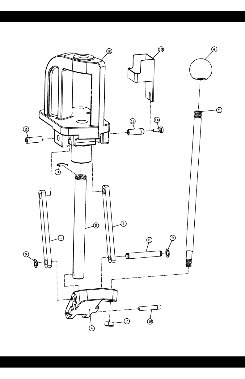
Mounting and Assembly
Your new Frankford Arsenal reloading press is shipped completely assembled and ready to use
with the exception of the operating handle and primer catcher. Prior to use, the press should
be securely mounted to a solid bench. The bench top should be rigid and at least 3 4” thick.
Mount and assemble the press as follows.
• Carefully position the press against the edge of the bench top in a convenient location.
The back of the ram support column and link arm supports should be flush with the
edge of the bench top. The press frame bottom should also set flush against the bench
top.
• Verify that the toggle block will not interfere with any portion of the bench
throughout its entire range of motion.
• With the press in the desired mounting location, mark the position of the mounting
holes using a pencil or punch.
• Remove the press and drill the 3 mounting holes in the bench top using a 3 8” drill bit.
• Secure the press assembly to the bench with the three 5 16” bolts (provided) using
1 2” box end wrenches or sockets. Be sure to use the flat washers (provided) above the
press frame and below the bench top.
• Slide the handle assembly into the hole in the toggle block . Secure the handle with the
1 2”-20 jam nut using a 3 4” box end wrench or socket.
• Screw the 1 4”-20 nylon thumbscrew into the threaded hole in the right side, upper
link pin. Back out the thumbscrew slightly. Slide the primer catcher slot downward over
the thumbscrew, with the primer catcher box facing the ram, until the primer catcher
rests firmly against the top of the frame. Secure by hand tightening the thumbscrew.
Do not over-tighten.
Maintenance and Lubrication
The press has been lubricated at the factory and is ready for use. However, the ram and link
pins should be lubricated periodically with SAE 30 weight motor oil or equivalent. Never use
penetrating lubricants, aerosol sprays, or solvent type lubricants, such as WD-40™ or Break
Free™. The press should be cleaned prior to lubrication to remove grit and other residue. If
rust spots appear on unpainted surfaces, swab with gun oil and wipe dry. If the press is to be
used in a damp area, all non-painted surfaces should be protected with a thin film of oil.
Painted surfaces may be cleaned with a damp cloth.
The primer catcher should be emptied periodically. Wipe away any accumulated grit and
primer residue from around the ram as well as any accumulations within the primer ejector slot
of the ram. Wipe up any excess oil that may also accumulate in the primer ejector slot.

Die Installation
The top of the press frame is threaded to accept all standard 7/8”-14 thread reloading dies.
Since die adjustment procedures vary ith the brand of dies used, it is recommended that you
first refer to the user instructions provided ith your particular die set.
Once adjusted, the die lock ring (provided ith the die) should al ays be tightened to secure
the die in place. To minimize case neck and bullet runout, al ays run an empty case or case
ith a seated bullet up into the die prior to tightening the die lock ring.
Note: Sizing dies should only be turned do n enough to take up the slack in the linkage sys-
tem. A toggle type compound linkage system can literally develop tons of force (at its toggle
point) sufficient to spring any press frame. Scre ing the sizing die do n more than necessary
( ell past top dead center) can potentially damage the shellholder, dies, and even the press if
the ram is forced to top dead center under these conditions.
Shellholder Installation
Shellholders are caliber specific and should be selected on the basis of the caliber of dies used.
The press ram is designed to use most popular brands of universal shellholders. Install by slid-
ing the shellholder into the slot at the top of the ram until it snaps in place. It is recommend-
ed that you rotate the shellholder slightly clock ise for easier access (about 60 degrees so that
the slot in the shellholder is perpendicular to the top of the frame). To remove the shellhold-
er, simply pull for ard (a ay from the bench).
Priming
Because hand priming tools offer the reloader a safer and more consistent “feel” for seating
primers, the Frankford Arsenal Model SS-99 press does not come ith a universal priming
arm. Universal priming arms lack the proper mechanical advantage and tactile feel necessary
for consistent primer seating depth, are cumbersome to use, and due to necessary frame offsets
and milled slots required for installation, compromise press frame structural integrity. If a
press- mounted priming system is desired, any of the many ram priming systems on the mar-
ket can be installed on the Model SS-99.
Warning
The Midway press has been designed specifically to handle the stresses of
heavy-duty reloading and case forming and is not recommended for use in
bullet swaging operations.
Note this press uses a positive mechanical stop in the compound linkage system to
terminate ram motion at top dead center. To prevent damage to the press, dies, and
shellholder, no further pressure should be applied to the operating handle once this
stop is reached.
The use of a cheater bar (or a pipe) on the press handle to gain additional mechan-
ical advantage may overstress press components. Evidence of such abuse will void
the warranty.
5
!

6
Troubleshooting Guide
A summary of common reloading problems and causes are listed below.
Case Insertion
1. Problem: Case will not slide into shellholder.
Possible Cause:
• Dirt in shellholder pocket.
• Damaged shellholder.
• rong shellholder.
• Case has bent rim.
• Cases not within SAAMI specs.
• High primer.
Resizing and Decapping
1. Problem: Case not properly sized.
Possible Cause:
• Sizing die not adjusted correctly.
• Press operating handle not cycled all the way down to stops.
2. Problem: Decapping pin not decapping.
Possible Cause:
• Decapping pin bent or broken.
• Die decapping stem improperly adjusted.
• Berdan primed case.
3. Problem: Bent or broken decapping pin.
Possible Cause:
• Berdan primed case.
• Flash hole not centered in case.
• An obstruction inside case.
4. Problem: Primers hang up in the ram primer ejector slot and do not discharge into the
primer catcher.
Possible Cause: Improperly adjusted decapping stem.
Remedy: The decapping stem is set too deep. Loosen the decapping stem and raise the
stem as needed. The decapping stem need only be set deep enough to eject the primer
and no further.
5. Problem: Oil dents in case shoulder or wrinkled casenecks.
Possible Cause: Using too much case sizing lubricant.
Remedy: Reduce the amount of lubricant used and disassemble and clean die as needed.
6. Problem: Crushed Cases.
Possible Cause:
• Not enough radius on die mouth.
• Case not centered in shellholder upon entry into die.
• Attempting a case forming operation that is too radical to perform in one step.

7
Remedy: Guide cases into die. If reforming cases, use case forming dies.
7. Problem: Scratched or marked cases.
Possible Cause:
• irty brass.
• Scratched die.
• Brass or nickel adhering to carbide insert. Use a good bore solvent to dissolve these
deposits.
8. Problem: Cases are hard to size and/or squeal during sizing.
Possible Cause:
• Not enough case lubricant used.
• Not enough time allowed for evaporation of carrier for spray type case lubricants.
9. Problem: Stuck case and torn case rims.
Possible Cause:
• Not enough case lubricant used.
• Not enough time allowed for evaporation of carrier for spray type case
lubricants.
Remedy: If the case rim is intact, rotate the shellholder until it is oriented to allow removal
from the press ram. Slide out the shellholder and unscrew the die. Use a stuck case
puller to remove the case. If the case rim is torn off, unscrew the die and use a stuck case
puller to remove the case. Remove torn rim from shellholder. Reinstall die and
lubricate cases properly.
Case Mouth Belling
1. Problem: Over or under flared cases.
Possible Cause:
• Improper die adjustment.
• Variations in case length.
Bullet Seating
1. Problem: Top of bullet is deformed.
Possible Cause:
• Case not flared enough.
• Soft lead.
• Lead or wax buildup in die.
• Incorrect seating stem for bullet style used.
2. Problem: Shaving lead or lube.
Possible Cause
• Case not flared enough.
• Bullets are not correct diameter.
• Burrs on case mouth.
3. Problem: Loose bullets.
Possible Cause:
• Over crimping.

8
• Incorrect bullet diameter.
4. Problem: Inconsistent seating depth.
Possible Cause:
• Variations in case and bullet dimensions.
• Lead or lube buildup in die seating stem.
• Incorrect seating stem for bullet style used.
Crimping
1. Problem: Cases are over or under crimped or crimping is not consistent.
Possible Cause:
• Over flared case.
• Die not properly adjusted.
• Variations in case length.
2. Problem: Loose bullets.
Possible Cause:
• Over crimping.
• Wrong expander.
• Thin cases.
Limited Warranty
Every Frankford Arsenal product is warrantied to be free of defects in materials and workman-
ship for a period of one (1) year from the date of original purchase. Frankford Arsenal will, at its
option, repair or replace without charge, except for transportation costs, parts that fail under nor-
mal use and service when operated and maintained in accordance with our Instructions. This war-
ranty does not apply to normal wear or to items whose life is dependent upon their use and care.
This warranty is in lieu of all other warranties, expressed or implied and releases Frankford
Arsenal, its affiliates, and its vendors from all other obligations and liabilities.
5885 W Van Horn Tavern Rd. • Columbia, MO 65203
Visit our web site at www.frankfordarsenal.com
Revised: 01-13-00 A Product
Table of contents
Popular Power Tools manuals by other brands

Planchas Termicas
Planchas Termicas I15H Operator's manual

Metabo HPT
Metabo HPT WR 18DBDL2 Safety instructions and instruction manual

DeWalt
DeWalt XR DCH614X2 Original instructions

molex
molex TM42 Operation manual

Parkside
Parkside 321231 1901 Translation of the original instructions

Carat
Carat CARDI A-2225 operating manual