GMP ACCELAIR 2 User manual
Copyright 2021 by General Machine Products (KT), LLC
All rights reserved. No part of this publication may be copied,
reproduced or transmitted in any form whatsoever without the
written permission of General Machine Products (KT), LLC
GMP • 3111 Old Lincoln Hwy • Trevose, PA 19053 • USA
TEL: +1-215-357-5500 • www.gmptools.com
February 15, 2021 USA ver 04H
Manual P/N 34061
ACCELAIR 2 BLOWN FIBER MACHINE
P/N 89500
OPERATION AND MAINTENANCE MANUAL

2
Rev
No. Date Details Author
01 05/30/14 Original Issue C. Swallow
02 05/01/15 US Version A. Konschak
03 05/25/16 Added Spares A. Konschak
04 02/10/17 Revised Program (mul language)
Changed menu opons A. Konschak
04a 03/01/17 Updated troubleshoong guide A. Konschak
04b 03/22/17 Updated Spares and Conguraon A. Konschak
04c 04/18/17 Added stop end adapters to P16 A. Konschak
04d 04/20/17 Updated blowing speed spec
Added min torque seng on P18 A. Konschak
04e 07/18/17 Changed company name A. Konschak
04f 03/06/18 Added shoulder strap A. Konschak
04g 03/26/18 Updated conguraon page A. Konschak
04h 02/15/21
Remove Polymetric Plates
Updated photos to reect latest changes
Update oered accessories A. Konschak
04i 04/26/21 Added remote control replacement A. Konschak
REVISION HISTORY

3
Contents
1. SAFETY INSTRUCTIONS........4
2. CRITICAL POINTS THAT DRAMATICALLY AFFECT THE OPERA-
TION OF THE BLOWN FIBER BLOWING MACHINE........8
3. GENERAL DESCRIPTION........10
4. SPECIFICATION........11
5. MAJOR ELEMENTS........12
6. OPERATING PROCEDURE........14
7. MAINTENANCE........25
8. PROCEDURE FOR CHANGING THE BLOWING PLATES........26
9. PROCEDURE FOR REPLACING TUBE CLAMP INSERTS AND IN-
FEED GUIDES........28
10. PROCEDURE FOR REPLACING DRIVE WHEELS........29
11. PROCEDURE FOR REPLACING AIR SEALS........30
12. CHECKING THE ODOMETER........31
13. DETERMINING MAXIMUM TORQUE SETTING........32
14. PROCEDURE FOR CHANGING DISPLAY LANGUAGE…..33
15. TROUBLESHOOTING GUIDE........34
16. MONTHLY SERVICE – CHECK LIST........35
17. CHANGEABLE PARTS AND ACCESSORIES ........36
18. SPARES…….38
GMP Limited Warranty can be found at hp://
www.gmptools.com/warranty/

4
1. SAFETY INSTRUCTIONS
THIS EQUIPMENT SHOULD BE USED ONLY BY PERSONNEL WHO
HAVE BEEN GIVEN THE APPROPRIATE TRAINING AND WHO ARE
COMPETENT TO USE IT.
THESE INSTRUCTIONS ARE TO BE MADE AVAILABLE TO OPERA-
TORS OF THIS EQUIPMENT AT ALL TIMES, FAILURE TO OBSERVE
THESE SAFETY INSTRUCTIONS COULD RESULT IN SERIOUS PER-
SONAL INJURY AND/OR PROPERTY DAMAGE.
WORK AREA AND GENERAL SAFETY
• Read and understand the operaon and maintenance
manual supplied with this equipment. Keep it in a
convenient place for future reference.
• Keep children and untrained personnel away from this equip-
ment while in operaon.
• Keep all guards and safety devices in place. Do not operate
this equipment with guards removed or damaged.
• Keep hands, feet and loose clothing away from moving parts.
• Always stop the machine and isolate compressed air and
electrical services to carry out servicing.
• Check machine before starng for worn or damaged parts.
Check for signs of loose nuts and bolts etc.
• If machine is le unaended, ensure that unauthorized use is
prevented. Never leave the machine unaended while in
use.
• Consider the use of safety barriers, especially when used in
public places, observe all statutory requirements for working
environments.
• Beware of pinch points involved with rotang components,
• Beware of hot surfaces, machine uses compressed air.

5
• When operang machine always wear appropriate safety
clothing, ear and eye protecon, hard hat, safety shoes and
leather gloves. The machine operates with compressed air at
up to 220 PSI (15 Bar).
• Prior to installaon ensure the tube route is connected
properly.
• Beware of exposed electrical contacts. Do not touch, or allow
metal objects to come into contact.
• Machine may cause addional re hazard if involved in an
exisng re due to compressed air.
• The machine must be operated on rm ground.
• Stay clear of pressurized airline and tube.
• Only use the machine for its intended purpose, to retrieve
ber blow air in the far end.
• The compressed air supply must not be allowed to enter the
air chamber before the lid has been securely ghtened.
• Ensure the ber exits easily from the pan. Place the pan a
sucient distance to allow the operator me to react should
the ber become tangled.
• The cable should enter the machine in a clean and dry condi-
on.
FAILURE TO DO SO MAY RESULT IN PERSONAL INJURY OR DAM-
AGE TO THE BLOWN FIBER.

6
If a power supply is used and the connecng plug on the power
lead to the generator / (or supply) is unsuitable and requires re-
placement, the new plug must be correctly connected observing
the color codes as below.
IT IS THE RESPONSIBILITY OF THE USER TO ENSURE THAT THE
CONNECTIONS MEET THE ELECTRICAL REGULATIONS FOR THE
RELEVANT COUNTRY.
The Accelair 2 machine itself runs o a 24V supply connected via
a Binder Series 430 Socket. Should the connecng plug need re-
placement the Red wire is posive (+ve) (Pin 1) and the Black
wire is negave (-ve) (Pin 3), pin 2 is unused.
Brown (Live)
Yellow & Green (Earth)
Blue (Neutral)

7
GENERAL PNEUMATIC SAFETY INSTRUCTIONS
The GMP Accelair 2 Blown Fiber Blowing Machine is a pneu-
mac device, using pressurized air to project ber at high ve-
locies. Please observe the following precauons when oper-
ang the Blowing Machine:-
• Compressed air can cause ying debris. This could cause
personal injury. Always wear personal protecve equip-
ment.
• Ensure no personnel are in the manhole at the far end of
the ber run. Severe personal injury may result.
• Never open the machine when pressurized.
• Only authorized, fully trained personnel should operate the
air compressor.
GENERAL ELECTRICAL SAFETY INSTRUCTIONS
The machine has electronic and electrical power and control
circuits. Electric shock hazards exist that could result in severe
personal injury. Observe the following precauons to avoid
electrical hazards:
Do not operate in water. Do not expose the machine to rain.
Do not remove cover of the power supply or the base from the
Accelair 2 machine. There are no user serviceable parts inside.
Refer servicing to qualied service personnel.

8
2. CRITICAL POINTS THAT DRAMATICALLY AFFECT
THE OPERATION OF THE BLOWN FIBER BLOWING
MACHINE
• Cord seals in air chamber correctly ed to provide good
sealing.
• Correct blowing plates ed.
• Tube fully connected and pressure-tested.
• Tube connecng ngs are suitable for operang at com-
pressor supply pressure.
• Accelair 2 lid securely ghtened.
• Compressor capacity is suitable for size of tube being used.
• Fiber pan must be close to the machine, the ber should
leave the pan freely and enter the machine horizontally.
• Air chamber, drive wheel, blown ber must be clean and
free from debris, glass beads, sludge, dirt, water and lubri-
cant.
• The ber must be hand guided into the machine.
• Ensure the compressed air supply is not applied to the ber
unl approximately 30 meters of ber has been installed or
the machine begins to slow down.
• The compressed air moisture content needs to be carefully
controlled, it should be dry enough to prevent moisture
forming in the tubes yet not so dry to cause a stac build
up – GMP Products recommend the use of an air dryer with
a bypass.

9
DISCLAIMER
GMP takes care in the design of its products to ensure that the
cable is protected during installaon. Due to the variety and
dierent methods of ber manufacture the responsibility of
checking the ber compability with the equipment lies with the
operator. Therefore, GMP cannot accept liability for any damage
to the ber.

10
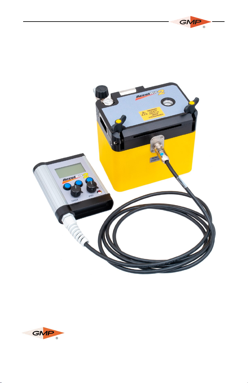
3. GENERAL DESCRIPTION
The Accelair 2 Fiber Blowing Machine has been developed to
provide a simple to use and reliable ber blowing soluon. The
unit is designed to t a ber range up to 3mm diameter, thereby
providing the complete range of blown ber installaon solu-
ons from one machine.
The Accelair 2 is a compact integrated ber blowing machine
beneng from full automaon and ber management; sophis-
cated ber protecon is implemented to ensure the ber me-
chanical and opcal integrity is maintained. The machine only
requires a single 24V D.C. electrical supply and compressed air to
operate.
GMP has designed a range of accessories aimed at providing the
complete soluon to blown ber installaon.

11
4. SPECIFICATION
Fiber
Compability:
Up to .8mm with buckle, up to 3mm with-
out buckle detecon
Blowing Speed: Manual control up to:
0-328 ./min (0-100m/min) without buckle
detecon
0-165 ./min (0-50m/min) with buckle
detecon
Compable Tubes: 3mm to 10mm
Automaon: In buckle mode machine is self-regulang
Air Supply: 15 Bar max working pressure complete with
suitable air condioning (drying)
Electrical
Supply:
Universal power supply (supplied as stand-
ard): 85-265V AC 50/60Hz input, 24V DC
2.2A output. Baery pack and vehicle
adapter available upon request.
Control: Remote user interface with backlit screen
provides all necessary informaon; includ-
ing current distance, speed, torque seng
and ber status.
Control interface supported languages:
English, French, German, Spanish,
Portuguese and Italian.
Machine size: H: 6.5" (166 mm) D: 7.2" (184 mm)
L: 4.7" (120 mm) Weight: 6.6 lbs. (3kg.)
Case size: H: 8.7" (220 mm) D: 18.9" (480 mm) L:
16.9" (430 mm)
Weight (case and unit): 26.5 lbs. (12kg
Environment: 0°C to +50°C (Usage)
-10°C to +70°C (Storage)
12
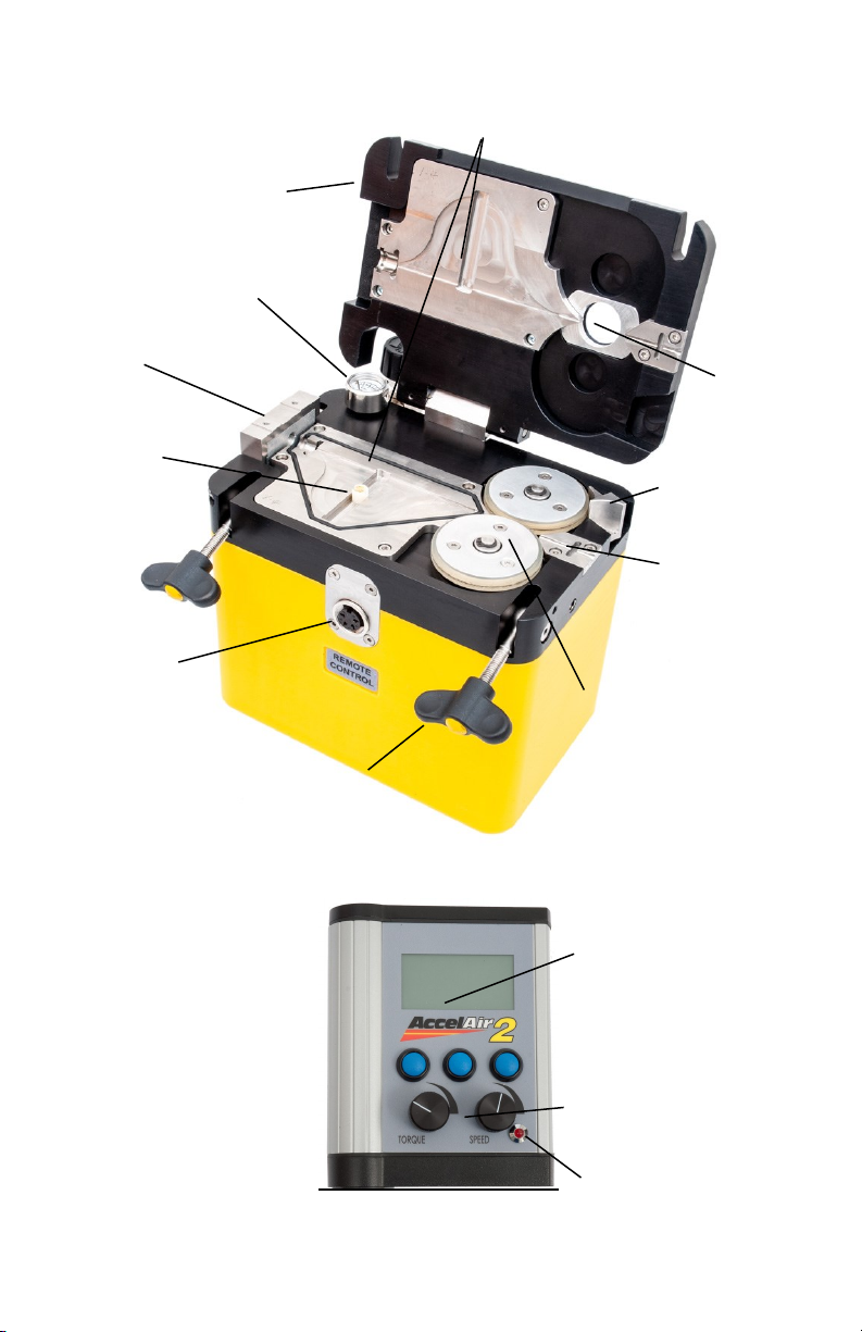
5. MAJOR ELEMENTS
Lid
Pressure
Gauge
Tube
Clamp
Buckle
Shule
Remote
Connecon
Buckle
Plates
Lid Locking
Screws
Sight Glass
Wheel Opening
Handle
Infeed Guide
Drive Wheels
LCD Display
Buckle Indicator
LED
User Interface
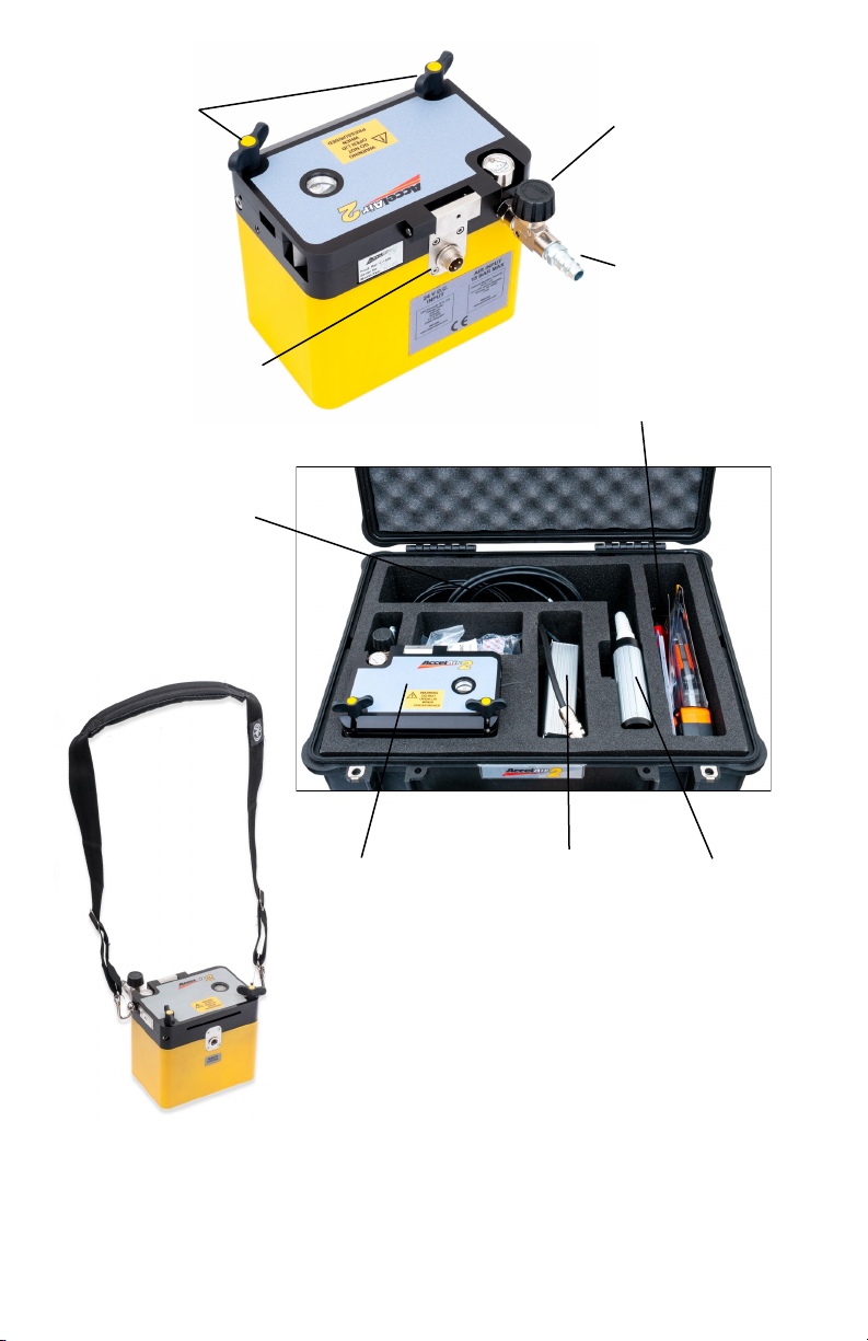
13
Air Control Valve
Air Connecon
24V Connecon
Lid Locking
Screws
Power Wires
Tools/Accessories
Universal AC-
Power Supply Remote UnitAccelair 2
Included with the Accelair is a removable
shoulder strap for added mobility when
working in mulple locaons.

14
6. OPERATING PROCEDURE
IT IS IMPERATIVE THAT ALL PERSONS USING, OPERATING OR
MAINTAINING THIS FIBER BLOWING MACHINE:
• HAVE RECEIVED COMPREHENSIVE TRAINING IN THE USE OF
THIS MACHINE
• ARE COMPETENT TO USE IT
• AUTHORIZED TO USE IT
• HAVE READ AND UNDERSTOOD THIS MANUAL
GMP CANNOT BE HELD RESPONSIBLE FOR MISUSE OF THIS
EQUIPMENT.
SETTING UP THE TUBE AND FIBER
To begin an installaon rst we must connect the tube and t
the ber through the machine. A selecon of changeable parts
are available to suit any combinaon of tube and ber. Please
consult secons 8, 9 and 10 for the procedures to t these
changeable parts and secon 16 for a list of available parts.
It is benecial and recommended to install a ber blowing bead
onto the end of the ber. Place the bead over the end of the
ber and use a small set of pliers to gently crimp it in place. Try
to deform the bead as lile as possible while holding it in place.

15
8. PROCEDURE FOR CHANGING THE BLOWING PLATES
The Accelair 2 uses two types of blowing plates. One type is for
use in conjuncon with the buckle funconality and one with-
out. The buckle plates use (4) M3 cap screws each to retain
them into the machine; the non-buckle plates use (3) each. The
supplied 2.5mm Allen wrench will be required for removal.
• Remove all retaining screws and li the plates out of the
machine.
• Inspect the condion of the air seal beneath the lower plate
and replace if necessary (photo overleaf).
• Replace plates of suitable size into the machine and ghten
the retaining screws rmly but take care not to damage the
aluminium threads.
Retaining
Screws
Retaining
Screws
Retaining
Screws
Retaining
Screws
No screw
No screw

16
Place the tube seal over the end of the
tube and insert into the machine as
shown with the tube ush up to the air
inlet and the seal
in the groove. Do
not allow the
tube to protrude
into the air inlet as this will restrict air
ow and performance.
Close the tube clamp by
pressing downwards; a
plunger will hold it in place.
Insert the end of the ber
into the tube and posion it
through the slot in the
buckle shule.
Open the drive wheels as
shown and place the ber in
the grooves on the buckle
plate and infeed guide.
17
The wheels are sprung and
will automacally close and
grip the cable once the han-
dle is released. Ensure the
ber runs smoothly through
the machine and is placed in
all grooves as shown.
Carefully close the lid,
ensuring the ber is not
caught or crushed.
Tighten the thumb screws
to seal the lid.
NEVER OPEN THE LID OF THE MACHINE WHEN IT IS UNDER PRES-
SURE, SERIOUS INJURY MAY OCCUR DUE TO ITEMS EXPELLED AT
HIGH VELOCITY.
GMP recommends the use of a stop end at the
end of the tube route to arrest the ber at the
end of the installaon.
4mm 3mm5mm
Adapters for 4 and 3mm microduct

18
FIBER INSTALLATION
Insure that the remote control and the power supply is connect-
ed to the unit before plugging into the power source. Aer sup-
plying power, the LCD panel on the remote unit should power up
with the following display.
Select the opon by pressing
the relevant blue buon under
either YES or NO depending on
the type of installaon you
wish to carry out and the
plates ed to the machine.
The buckle sensor ulizes plates with the buckle shule - this
can be seen in the photo at the top of the previous page. Should
the wrong selecon be made this can be altered in the menu
system, this is detailed later in this secon.
Once the selecon is made, a conrmaon screen is briey dis-
played followed by one of the screens below:
If a job has not been nished then it will remain acve in
memory and the screen on the right will be visible. It is then pos-
sible to either resume that job or start a new job. The blue
buons allow navigaon through the menus and the funcons
of these buons are displayed on the screen. Starng a new job
will present you with the following display.
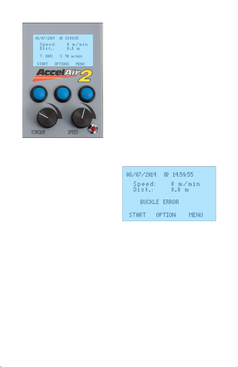
19
The two dials control the torque
seng and speed. Adjustment of
the torque seng is only relevant
when installing ber with the
buckle funconality disabled. The
torque should be set to a
minimum value of 20% when
buckle funconality is enabled to
ensure proper operaon.
This message will be displayed
if the buckle mode is selected
and the shule cannot be
detected. This is either because
the ber is buckled in the
machine or because you are
aempng to install with a
straight plate but have not
disabled the buckle
funconality.

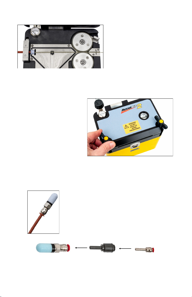
20
To check the buckle funcon
and to allow a viewing point
for the ber we suggest a
small length of tube with a
clear connector be used in
the machine rst. Moving
the ber in and out should
be possible; the screen
should display that the
buckle shule is moving.
Should the incorrect buckle
mode be selected at power up
select ‘MENU’ if not already
there and then select
‘SETTINGS’. When on the buckle
sensor opon press ‘Change’ to
alter this funcon. You can then return to the menu and resume
acve job; the error will now have disappeared.
This manual suits for next models
1
Table of contents
Other GMP Power Tools manuals


