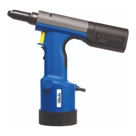
Gesipa taurus 1 User manual

TAURUS 1-2-3-4
Blindniettechnik GmbH
®
GESIPA Blindniettechnik GmbH
Nordendstraße 13-39
D-64546 Mörfelden-Walldorf
Telefon 0 6105/9 62 - 0
Telefax 0 6105/9 62 - 2 87
Internet http://www.gesipa.com
E-Mail info@gesipa.com
Pneumatisch-hydraulische
Blindnietgeräte
Betriebsanleitung
Pneumatic-hydraulic
Riveting Tools
Operating instructions
Pistolets à riveter
oléo-pneumatiques
Mode d‘emploi
Remachadoras neumatico-
hidràulicas para remaches ciegos
Manuell de instrucciones
Rivettatrice
Oleopneumatica
Istruzioni per l‘uso
Pneumatisch-hydraulische
blindklinkpistolen
Bedienings- en onderhouds Handleidning
Pneumatisk-hydraulisk
blindnittepistol
Betjeningsvejledning
Pneumatisk-hydrauliske
blindnitverktyg
Bruksanvisning
Pneumatisk-hydrauliske
blindnagleverktøy
Bruksanvisning
Pneumaattis-hydrauliset
sokkoniitauspistoolit
Käyttöohje
Pistolas pneumaático-hidráulicas
para rebitagem
Manual de instruções
Nitownice
pneumatyczno-hydrauliczne
Instrukcja Obsługi
Pneumatikus-hidraulikus
vakszegecs-anya pisztolyok
Felhasználói Kézikönyv
Pneumaticko-hydraulická
pistole pro slepé ny´tování
Návod k pouzˇití

Seite 5 – 10 Zum Lesen der Bedienungsanleitung
bitte die erste Umschlagseite herausklappen.
Page 11 – 16 When reading these instructions,
please open the first cover leaf.
Page 17 – 22 Mode d‘emploi:
déplier la première page de couverture.
Página 23 – 28 Para leer las instrucciones de manejo,
desdoblar la primera página de la cubierta.
Pagina 29 – 34 Per leggere le istruzioni d’uso
aprire la prima pagina.
Bladzijde 35 – 40 Voor het lezen van de gebruksaanwijzing
deze bladzijde openslaan.
Side 41 – 46 Slå den første side ud for bedre at kunne læse
og forstå betjeningsvejledningen.
Sida 47 – 52 Vid läsning af bruksanvisning
skall första sista omslags sidorna vikasut.
Side 53 – 58 Vennligst les forsiden først for å få en bedre
rettledning og forståelse av bruksanvisningen.
Sivu 59 – 64 Lukiessasi tätä käyttöohjetta käännä
etummainen kuvasivu esiin.
Página 65 – 70 Para ler as instruções de uso,
favor abrir a folha no verso da capa.
Strona 71 – 76 Aby przeczytac´ instrukcje˛ obsługi prosze˛
rozłoz˙yc´ pierwsza
˛strone˛ okładki.
Oldal 77 – 82 A kezelési útmutató elolvasásához kérjük
nyissa fel az also˝ borítóoldalt.
Strana 83 – 88 Prˇi cˇtení návodu první stranu otocˇit.

A
A
A-A (T2+T3+T4)
100,101
99
96
A-A (T1)
48
47
43,43a,44
1-14 17
18,19
16 24
21,22
15
25 26
17
27,28 ,28a
29
17
30 31 32
33 34
34b
35
36
37
38,38a,39
49
42
41
40
103,104
46
45
75
97,98
94
95
102
93
90
91 92
90a
51
50
52
53
56
54, 55, 55a
61,62,63
58,59,60,60a
57
64,89
75
72,73,74,74a
69,70,71,71a
67,68,68a
65,66,66a
76,77,78
79,80,81
82,83
84,85
87
88
50
86
34a
111
113 114 23
110 15
112
T3+T4
99a
T4
3
TAURUS 1-2-3-4

•
•
•
Ersatzteile
Spare Parts
Pièces détachées
Piezas de recambio
Lista dei pezzi di ricambio
Onderdelen
Reservedele
Reservdelsar
Reservedeler
Varaosaluettelo
Peças sobressalentes
Cze˛s´ci zamienne
Alkatrészek
Náhradní díly
4
758 1165
756 1113
756 1857
756 1849
757 1349
756 1121
758 1018
756 1083
756 1091
770 2426
756 1865
757 1224
715 8688
756 1016
756 2098
756 1024
756 1776
757 1216
759 1014
756 1032
756 1040
756 2101
757 1240
758 1114
759 1003
756 2039
757 1194
758 1157
756 1938
756 1768
757 1127
759 1013
756 1741
756 1989
7562012
756 2152
757 1275
758 1149
759 1006
756 2144
757 1267
1
2
3
4
5
6
7
8
9
10
11
12
13
14
15
16
17
18
19
21
22
23
24
25
26
27
28
28a
29
30
31
32
33
34a
34b
34
35
36
37
38a
38
T1,T2
T1
T2
T1
T2
T3,T4
T1,T2
T1
T2 ,T3
T4
T1
T2
725 2075
725 1583
725 2040
725 2059
725 2067
725 2083
725 2560
724 3065
725 2202
725 2210
725 2229
725 2237
725 2250
724 3146
756 1172
756 1180
756 1199
756 1164
757 1046
756 1156
757 1038
758 1025
756 1202
756 1377
756 1997
756 2047
757 1232
759 1002
756 1342
756 1229
756 1261
756 2055
756 1369
756 1034
756 1031
756 1385
756 1393
756 2063
756 1431
757 1352
756 1075
39
40
41
42
43a
43
44
45
46
47
48
49
50
51
52
53
54
55
55a
56
57
58
59
60
60a
61
62
63
64
65
66
66a
67
68
68a
69
70
71
71a
72
73
T3,T4
T1
T2
T3,T4
T1
T2 ,T3
T4
T1
T2
T3
T4
T1
T2
T3,T4
T1
T2 ,T3
T4
T1
T2 ,T3
T4
T1
T2
T3
T4
T1
T2
•
•
•
•
•
•
•
•
•
•
•
•
•
•
•
•
•
•
•
•
•
758 1130
759 1005
725 2032
756 1059
757 1011
758 1017
756 1806
757 1151
758 1173
7561792
757 1143
756 1784
756 1431
756 1539
756 1520
756 2071
756 1970
756 1030
756 2136
756 1628
756 1660
756 1601
756 2012
756 1687
756 1636
757 1070
758 1068
756 2160
759 1001
757 1348
758 1211
756 2209
756 2020
758 1238
759 1010
759 1009
759 1007
759 1004
759 1008
74
74a
75
76
77
78
79
80
81
82
83
84
85
86
87
88
89
90a
90
91
92
93
94
95
96
97
98
99
99a
100
101
102
103
104
110
111
112
113
114
T3
T4
T1
T2
T3,T4
T1
T2
T3,T4
T1
T2,T3,T4
T1
T2,T3,T4
T1
T2
T3,T4
T4
T2
T3,T4
T1,T2
T3,T4
T3,T4
T3,T4
T3,T4
T3,T4
T3,T4
TAURUS 1 =T1 TAURUS 2 =T2 TAURUS 3 =T3

Inhaltsverzeichnis Seite
1. Bestimmungsgemäße Verwendung ................................................. 6
2. Sicherheitshinweise .............................................................................. 6
3. Arbeitsbereiche ..................................................................................... 6
4. Technische Daten ................................................................................... 6
5. Ausrüstung/Zubehör ........................................................................... 7
6. Mundstücks-Zuordung ......................................................................... 7
7. Inbetriebnahme
7.1 Auffangbehälter aufsetzen
.................................................................... 8
7.2 Auswahl und Wechsel des Mundstücks
.................................................. 8
7.3 Setzen eines Blindnietes
........................................................................ 8
7.4 Ansaugen und Halten eines Blindnietes
................................................. 8
7.5 Entleerung des Auffangbehälters
........................................................... 8
8. Wartung und Pflege
8.1 Futterbacken ölen
................................................................................. 8
8.2 Futterbacken wechseln
.......................................................................... 8
8.3 Hydrauliköl nachfüllen
.......................................................................... 8
8.4 Lagerung
.............................................................................................. 9
9. Reparatur ................................................................................................ 9
10. Behebung von Störungen
10.1 Blindniet wird nicht gesetzt
................................................................. 9
10.2 Restdorn wird nicht abgesaugt
............................................................ 9
11. Garantie .................................................................................................. 9
12. Konformitätserklärung ................................................................ 10
5

1. Bestimmungsgemäße
Verwendung
Das Nietgerät darf nur, wie in dieser Anleitung
beschrieben, zum Setzen von Blindnieten ver-
wendet werden.
Die Sicherheitshinweise sind einzuhalten!
2. Sicherheitshinweise
Das Nietgerät ist ausschließlich zum Setzen
von Blindnieten zu verwenden.
Überlasten Sie das Nietgerät nicht, arbeiten
Sie im angegebenen Leistungsbereich.
Nicht ohne Fügegut nieten. Der Blindniet
kann vom Nietgerät wegspringen. Niet-
geräte nie gegen sich oder andere Personen
richten.
Der Auffangbehälter für Restdorne muß beim
Betrieb des Nietgerätes stets aufgeschraubt
sein.
Der Auffangbehälter ist rechtzeitig zu ent-
leeren; Überfüllung führt zu Störungen am
Nietgerät.
Das Nietgerät darf nicht als Schlagwerkzeug
benutzt werden.
Druckluftanschlußleitungen regelmäßig auf
Festsitz und Dichtheit kontrollieren.
Bei Wartungsarbeiten am Nietgerät und
bei Nichtgebrauch ist das Gerät immer vom
Druckluftnetz zu trennen.
Beim Arbeiten mit dem Nietgerät stets
Schutzbrille tragen. Persönliche Schutzaus-
rüstung wie Schutzkleidung, Handschuhe,
Sicherheitshelm, rutschfeste Schuhe, Gehör-
schutz und Sicherung gegen Absturz wird
empfohlen.
Zulässigen Betriebsdruck nicht überschreiten.
Beim Ablegen das Nietgerät gegen Herun-
terfallen sichern.
Reparaturen sind nur durch eine geeignete
Fachkraft auszuführen. Im Zweifelsfalle ist
das Nietgerät unzerlegt an den Lieferer oder
GESIPA einzusenden.
6
alle Werkstoffe
Gerätetyp
Standardblindniete Ø (mm)
ca.100 bis 200 je nach Größe
TAURUS 2
1,6
5
-
7
18
6
ca.2,3
9.000
ca.30
78
< 2,5
✔
✔
✔
3. Arbeitsbereiche
4. Technische Daten
Gerätetyp
Gewicht (kg)
Betriebsdruck (bar)
Gerätehub (mm)
Schlauchanschluß Ø (mm)
Volumen Auffangbehälter (Restdorne)
Luftverbrauch (NI/Niet)
Setzkraft bei 5 bar (N)
Hydrauliköl, ISO VG 32 bis 46 (ml)
Geräuschemmission Lpa (dB)
Vibration (m/s2)
Druckluftqualität (gefiltert)
Integrierte Restdornabsaugung
Integrierte Blindnietansaugung
TAURUS 1
1,3
5
-
7
15
6
ca.1,0
4.200
ca.30
77
< 2,5
✔
✔
✔
TAURUS 3
1,9
5
-
7
25
6
ca.4,8
14.000
ca.30
79
< 2,5
✔
✔
✔
TAURUS 4
2,0
5
-
7
19
6
ca.4,8
20.000
ca.30
79
< 2,5
✔
✔
✔
TAURUS 2
bis 5
bis 6 Alu
TAURUS 1
2,4 – 3,2
bis 4 Alu
TAURUS 3
bis 6,4
bis 8 Alu
TAURUS 4
bis 6,4
bis 8 Alu

7
5. Ausrüstung/Zubehör
6. Mundstücks–Zuordnung
TAURUS 2
17/27
17/29
17/32
17/36
✔
✔
✔
✔
TAURUS 1
17/18
17/24
17/27
✔
✔
✔
✔
TAURUS 3/4
17/36
17/40
17/45
✔
✔
✔
✔
Gerätetyp (Artikel-Nr.)
Mundstück in Arbeitsposition
Mundstücke am Geräteboden
1 Montageschlüssel SW12/14 (756 2195)
1 Montageschlüssel SW14/17 (756 2187)
1 Flasche Hydrauliköl 100 ml (715 8955)
1 Öl-Nachfüllbehälter (756 2179)
Mundstück
17/18
17/18
17/24
17/24
17/27
17/29
17/29
17/32
17/36
17/36
17/40
17/40
17/45
17/45
Niet-Werkstoff
Alu
CAP-Alu, CAP-CU
Alu, CU, Stahl, Edelstahl, Stinox,
Alu/Alu, PG-Alu, PG-Stahl
Alu, CU, CAP-Alu, CAP-Cu
Stahl, Alu/Alu, PG-Alu
Edelstahl, Stinox, PG-Stahl
Alu, CAP-Alu, CAP-CU, PG-Alu
Stahl, Alu/Alu
Edelstahl, Stinox, PG-Stahl
Alu
Stahl
Alu
Stahl, Alu/Alu
Alu
Artikel-Nr.
725 2075
725 2075
725 1583
725 1583
725 2040
725 2059
725 2059
725 2067
725 2083
725 2083
725 2560
725 2560
724 3065
724 3065
Niet Ø (mm)
2,4
3,2
3 und 3,2
4
4
4
5 und 4,8
5 und 4,8
5 und 4,8
6
6
6,4
6,4
8
Mundstück
17/26 BT*
17/32 BT*
17/42 BT*
17/48 BT*
Niet-Werkstoff
Alu/Alu
Alu/Alu
Alu/Alu, Stahl/Stahl, Monel/Edelstahl
Alu/Alu
Artikel-Nr.
725 2202
725 2210
725 2229
725 2237
BULB-TITE Ø (mm)
4
5,2
6,3
7,7
Mundstück
17/31 MG*
17/41 MG*
Niet-Werkstoff
Alu/Alu, Stahl/Stahl, Edelstahl
Artikel-Nr.
725 2250
724 3146
MEGA-GRIP Ø (mm)
4,8
6,4
*Mundstücke in verlängerter Ausführung und weitere Spezialausführungen sind auf Anfrage als
Sonderzubehör lieferbar.

7. Inbetriebnahme
Vor Inbetriebnahme Betriebsanleitung sowie
Sicherheitshinweise lesen, beachten
(!)
und
sorgfältig aufbewahren.
Druckluftnetzanschluss zum Nietgerät durch
Fachkraft erstellen.
7.1 Auffangbehälter aufsetzen
Auffangbehälter für Restdorne bis zum An-
schlag (durch Rechtsdrehung) aufschrauben.
7.2
Auswahl und Wechsel des Mundstückes
Achtung!
Immer das der Blindnietgröße
entsprechende Mundstück einsetzen.
(Auswahl nach Tabelle gemäß Punkt 6)
Wechsel des Mundstückes
– Nietgerät vom Druckluftnetz trennen.
– Mundstück von Stahlhülse abschrauben.
– Ausgewähltes Mundstück einschrauben
und festziehen.
7.3 Setzen eines Blindnietes
– Nietgerät an Druckluftnetz anschließen.
– Blindniet in das Mundstück einstecken
und mit dem Nietgerät bis zum Anschlag
in die Fügegut-Bohrung einführen.
– Auslöser betätigen bis der Nietdorn abreißt.
– Auslöser loslassen.
– Der Restdorn wird automatisch in den
Auffangbehälter gefördert (s.Pkt.7.5).
7.4
Ansaugen und Halten eines Blindnietes
Diese Funktion dient dazu, den Blindniet im
Mundstück des Nietgerätes zu halten, wenn
senkrecht nach unten genietet werden soll.
– Absperrventil Nr.88 im Nietgerätekopf mittels
Stift (z.B. Nietdorn) nach links oder rechts bis
zum Anschlag schieben.
– Nach dem Greifen des Nietgerätes den
Schieber Nr.86 bis zum Einrasten nach oben
schieben. Zum Ausschalten der Ansaugung
den Schieber nach unten schieben.
– Durch Zurückschieben des Absperrventils
Nr.88 wird die komplette Ansaugfunktion
des Gerätes abgestellt.
7.5 Entleerung des Auffangbehälters
– Der Auffangbehälter ist rechtzeitig zu ent-
leeren; Überfüllung führt zu Störungen am
Nietgerät.
– Auffangbehälter durch Linksdrehung ab-
schrauben, Restdorne in geeignetem Behälter
sammeln.
– Auffangbehälter aufschrauben.
8. Wartung und Pflege
Der komplette Greifmechanismus muß regel-
mäßig gewartet werden.
8.1 Futterbacken ölen
– Nietgerät vom Druckluftnetz trennen
– Stahlhülse Nr.24 abschrauben
– Kompletten Futtermechanismus bis zum
O-Ring Nr.17 in Ölbad tauchen bzw.
Futterbacken Nr.15 mit Öl benetzen und
abtropfen lassen.
– Zusammenbau in umgekehrter Reihenfolge
8.2 Futterbacken wechseln
– Gerät vom Druckluftnetz trennen
– Stahlhülse Nr.24 abschrauben
– Futtergehäuse Nr.16 abschrauben
– Futterbacken Nr.15 entnehmen
–
Futtergehäuse reinigen und Gleitflächen fetten
– Neue Futterbacken von vorn einsetzen
(werden vom Fett gehalten)
– Zusammenbau erfolgt in umgekehrter
Reihenfolge; alle Teile fest miteinander
verschrauben.
8.3 Hydrauliköl nachfüllen
– Nietgerät vom Druckluftnetz trennen.
– Stahlhülse Nr.24 abschrauben.
– Öl-Nachfüllschraube Nr.30 und Dichtung
Nr.31 mit Torx-Schraubendreher T20
abschrauben.
– Beiliegenden Öl-Nachfüllbehälter mit Deckel
aufschrauben.
– Nietgerät an Druckluftnetz anschließen und
Auslöser betätigen; danach Nietgerät vom
Druckluftnetz trennen.
– Altes Öl aus Öl-Nachfüllbehälter ausgießen.
– Öl-Nachfüllbehälter bis zur Markierung mit
Hydrauliköl füllen.
– Zugkolbeneinheit von Hand mehrfach vor-
sichtig hin- und herbewegen bis Öl blasenfrei
austritt; Zugkolbeneinheit vollständig bis
Anschlag nach hinten schieben und hinten
stehen lassen.
– Öl-Nachfüllbehälter abschrauben und Öl-
Nachfüllschraube mit Dichtung einschrauben.
– Nietgerät an Druckluftnetz anschließen und
Nietgerät zweimal auslösen.
– Öl-Nachfüllschraube vorsichtig ca. 2 Umdre-
hungen lösen; Zugkolbeneinheit bewegt sich
langsam bis in die vordere Endlage.
Dabei austretendes Öl mit Lappen auffangen.
– Öl-Nachfüllschraube festziehen
– Stahlhülse aufschrauben.
8


8.4 Lagerung
Der Aufbewahrungsort für das Nietgerät soll
trocken und frostsicher sein
9. Reparatur
Garantiereparaturen werden grundsätzlich
vom Hersteller durchgeführt.
Reparaturen außerhalb der Garantiezeit sind
nur von fachkundigem Personal
auszu-
führen. Nichtbeachtung von Montage- und Ein-
stellvorschriften als auch nicht-fachkundiger
Umgang können zu schwerwiegenden Schäden
am Nietgerät führen. Im Zweifelsfall ist das
Nietgerät an den Lieferer oder
GESIPA
einzu-
senden.
10. Behebung von Störungen
10.1 Blindniet wird nicht gesetzt
– Futterbacken Nr.15 verschmutzt – reinigen und Gleitflächen ölen (siehe Pkt.8.1)
– Futterbacken Nr.15 stumpf – wechseln (siehe Pkt.8.2)
– Betriebsdruck nicht ausreichend – siehe Betriebsdruck (siehe Pkt.4)
– Gerätehub zu gering – Hydrauliköl nachfüllen (siehe Pkt.8.3)
10.2 Restdorn wird nicht abgesaugt
– Auffangbehälter voll – leeren (siehe Pkt.7.5)
– falsches Mundstück verwendet – gemäß Tabelle austauschen (siehe Pkt.6)
– Mundstück verschlissen – erneuern
– Restdorn in Futterbacken verkeilt – Futterbacken und Futtergehäuse reinigen
und Gleitflächen ölen; bei Verschleiß
erneuern (siehe Pkt.8.2)
Abhilfe
Ursache
Abhilfe
Ursache
9
11. Garantie
Für dieses Nietgerät leisten wir 12 Monate
Garantie ab Liefertag.
(Nachweis durch Rechnung oder Lieferschein)
Schäden die auf natürliche Abnutzung, Über-
lastung oder unsachgemäße Behandlung
zurückzuführen sind, werden von der Garantie
ausgeschlossen.
Schäden die durch Material- oder Herstellungs-
fehler entstanden sind, werden unentgeltlich
durch Ersatzlieferung oder Reparatur beseitigt.
Beanstandungen können nur anerkannt werden,
wenn das Gerät
unzerlegt
an den Lieferer oder
an
GESIPA
gesandt wird.

10
12. Konformitätserklärung
Hiermit erklären wir, dass die Bauart der pneumatisch
-
hydraulischen Blindnietgeräte
TAURUS 1 TAURUS 2 TAURUS 3 TAURUS 4
bei bestimmungsgemäßer Verwendung den nachfolgend angeführten Normen, Gesetzen und
Vorschriften entspricht:
98/37/EG
H.U.Harder
(Sicherheitsbeauftragter)

Table of Content Page
1. Conditions of use .................................................................................. 12
2. Safety Notes ........................................................................................... 12
3. Working Range ..................................................................................... 12
4. Technical Data ........................................................................................ 12
5. Equipment/Accessories ........................................................................ 13
6. Nosepiece table ..................................................................................... 13
7. Starting Procedure
7.1 Installing the mandrel container
............................................................ 14
7.2 Selecting and changing a nosepiece
...................................................... 14
7.3 Setting a blind rivet
............................................................................... 14
7.4 Suction and holding a blind rivet
........................................................... 14
7.5 Emptying the mandrel container
............................................................ 14
8. Maintenance and Care
8.1 Lubricating the jaws
.............................................................................. 14
8.2 Changing jaws
...................................................................................... 14
8.3 Refilling the hydraulic fluid
.................................................................... 14
8.4 Storage conditions
................................................................................ 15
9. Repair operations ................................................................................. 15
10. Troubleshooting
10.1 Blind rivet does not set
........................................................................ 15
10.2 Spent mandrel is not evacuated
.......................................................... 15
11. Warranty Conditions ............................................................................ 15
12. Conformity Declaration ................................................................ 16
11

Type of tool
Standard blind rivet Ø (mm)
1. Conditions of Use
This blind rivet setting tool may be used only
to set blind rivets, as described in the operating
instructions.
The safety instructions MUST be followed!
2. Safety Notes
Use the tool ONLY to set blind rivets
Never overload the tool: Work within the
stated performance parameters
Never operate the tool without placing the
blind rivet in the hole of the workpiece
or the rivet could come off the tool! Do not
point the tool head towards yourself or
anyone else!
The spent-mandrel container should always
be screwed tightly on to the tool whilst in
operation.
Regularly empty the spent mandrel container:
Overloading may cause damage to the tool.
Do not use the tool as a hammer.
Regularly check the compressed air connec-
tions for 'play' and leakage.
Prior to maintenance and when not in use,
always disconnect the tool from the com-
pressed air supply.
Safety glasses should always be worn when
using the riveting tool. The use of any per-
sonal protective clothing is always recom-
mended.
Do not exceed the air pressure limit of the
tool.
When not in use, make sure that the tool
cannot fall to the floor.
Repairs should be carried out only by quali-
fied staff. When in doubt, the tool should be
sent back (not dismantled) to the supplier or
to Gesipa.
12
3. Working Range
4. Technical Data
Type of tool
Weight (kg)
Operating pressure (bar)
Stroke (mm)
Air connecting hose Ø (mm)
Spent mandrel container capacity
(spent mandrels)
Air consumption (Liter/rivet)
Setting Power at 5 bar (N)
Hydraulic fluid ISO VG 32 up to 46 (ml)
Noise emission Lpa (dB)
Vibration (m/s2)
Compressed air requirement (filtered)
Integrated spent mandrel ejection
Integrated rivet retention
all materials
approx. 100 to 200 acc. to size
TAURUS 2
1,6
5
-
7
18
6
approx.2,3
9.000
approx.30
78
< 2,5
✔
✔
✔
TAURUS 1
1,3
5
-
7
15
6
approx.1,0
4.200
approx.30
77
< 2,5
✔
✔
✔
TAURUS 3
1,9
5
-
7
25
6
approx.4,8
14.000
approx.30
79
< 2,5
✔
✔
✔
TAURUS 4
2,0
5
-
7
19
6
approx.4,8
20.000
approx.30
79
< 2,5
✔
✔
✔
TAURUS 2
up to 5
up to 6 Alu
TAURUS 1
2,4 – 3,2
up to 4 Alu
TAURUS 3
up to 6,4
up to 8 Alu
TAURUS 4
up to 6,4
up to 8 Alu

13
5. Equipment/Accessories
6. Nosepiece table
TAURUS 2
17/27
17/29
17/32
17/36
✔
✔
✔
✔
TAURUS 1
17/18
17/24
17/27
✔
✔
✔
✔
TAURUS 3/4
17/36
17/40
17/45
✔
✔
✔
✔
Type of tool (Part-N°.)
Nosepiece in working position
Nosepieces in tool base
1 wrench SW12/14 (756 2195)
1 wrench SW14/17 (756 2187)
1 bottle of Hydr. fluid 100 ml (715 8955)
1 oil filling container (756 2179)
Nosepiece
17/18
17/18
17/24
17/24
17/27
17/29
17/29
17/32
17/36
17/36
17/40
17/40
17/45
17/45
Rivet Material
Alu
CAP-Alu, CAP-CU
Alu, CU, Steel, Stainl. Steel, Stinox,
Alu/Alu, PG- Alu, PG-Steel
Alu, CU, CAP-Alu, CAP-Cu
Steel, Alu/Alu, PG-Alu
Stainl. Steel, Stinox, PG-Steel
Alu, CAP-Alu, CAP-CU, PG-Alu
Steel, Alu/Alu
Stainl. Steel, Stinox, PG-Steel
Alu
Steel
Alu
Steel, Alu/Alu
Alu
Part-N°.
725 2075
725 2075
725 1583
725 1583
725 2040
725 2059
725 2059
725 2067
725 2083
725 2083
725 2560
725 2560
724 3065
724 3065
Rivet Ø (mm)
2,4
3,2
3 and 3,2
4
4
4
5 and 4,8
5 and 4,8
5 and 4,8
6
6
6,4
6,4
8
Nosepiece
17/26 BT*
17/32 BT*
17/42 BT*
17/48 BT*
Rivet Material
Alu/Alu
Alu/Alu
Alu/Alu, Steel/Steel, Monel/Stainl. Steel
Alu/Alu
Part-N°.
725 2202
725 2210
725 2229
725 2237
BULB-TITE Ø (mm)
4
5,2
6,3
7,7
Nosepiece
17/31 MG*
17/41 MG*
Rivet Material
Alu/Alu, Steel/Steel, Stainl. Steel
Part-N°.
725 2250
724 3146
MEGA-GRIP Ø (mm)
4,8
6,4
*Available as a special accessory
Elongated nosepieces and further special nosepieces available on request.

7. Starting Procedure
Before use, read, pay attention to and carefully
keep both the operating and safety instructions.
Ensure a specialist.connects the compressed air
supply to the riveting tool
7.1 Installation of the spent mandrel
Screw the spent mandrel container on to the
tool by turning it clockwise.
7.2
Selection and exchange of nosepieces
Attention:
Always use a nosepiece
corresponding to the blind rivet size
(selection according to table point 6.)
Exchanging nosepieces
– Disconnect the tool from the compressed air
– Unscrew the nosepiece from the tool head
– Screw in and tighten the replacement nose-
piece.
7.3 Setting a blind rivet
– Connect the tool to the compressed air.
– Insert the blind rivet into the nosepiece and
place the rivet into the workpiece
– Press the yellow trigger until mandrel breaks.
– Release the yellow trigger
– The mandrel is automatically transported to
the mandrel container (see point 7.5)
7.4
Suction and holding of a blind rivet
This feature allows the blind rivet to be held
in the tool nosepiece for vertical, downwards
riveting.
– Open the ON/OFF valve N° 88 in the tool
head by pushing it to the right or left stop
with a pin (e.g. a mandrel) to enable the
suction feature.
– After Closing the hand on the pistol grip push
slider N° 86 upwards to stop to switch on the
suction. Pushing slider N° 86 downwards will
switch off the suction.
– Pushing back the ON/OFF valve N° 88 will
permanently disable the suction feature.
7.5 Emptying the mandrel container
– The mandrel container must be emptied
regularly; Overfilling causes the tool to mal-
function.
– Unscrew the container counter-clockwise and
dispose of spent mandrels according to valid
recycling procedures.
– Screw the spent mandrel container back on
to the tool.
8. Maintenance and Care
The complete jaw assembly must be regularly
maintained.
8.1 Lubricating the jaws
– Disconnect the tool from the compressed air
– Screw off steel head N° 24
– Dip the complete jaw housing into oil as far
as N° 17 O-ring, or spray oil on Jaws N° 15
– Reassemble in reverse order.
8.2 Exchanging jaws
– Disconnect the tool from the compressed air
– Screw off steel head N° 24
– Screw off jaw housing N° 16
– Remove jaws N° 15
–
Clean jaw housing and grease friction
surfaces
– Insert new jaws from the front (grease will
hold in position)
– ReasseHydraulic fluid refill
8.3 Hydraulic fluid refill
– Disconnect the tool from the compressed air
– Screw off steel head N° 24
– Unscrew and remove fluid refill screw N° 30
c/w sealing ring N° 31, using a T20 Torx
screwdriver
– Screw on included oil filling container
with cover
– Reconnect the tool to the air pressure and
depress yellow trigger once. Disconnect the
tool from compressed air
– Empty old oil from the oil container.
– Fill oil container with new hydraulic fluid,
up to mark
– Move traction rod back and forth carefully
several times by hand until oil escapes
bubble-free. Push traction rod fully back up
to stop and leave in this position.
– Remove oil filling container and screw back
sealing ring and refill screw
– Reconnect the tool to compressed air and
depress trigger twice.
– Carefully loosen oil filling screw by 2 revs;
Traction rod will move slowly up to forward
stop. Wipe away spilt oil.
– Retighten oil filling screw
– Screw on steel head N° 24
14

8.4 Storage conditions
Keep tool in a dry, frost-proof area
9. Repair
In principle, warranty repairs should only
be carried out by the manufacturer.
When warranty expires, repairs should be
carried out by trained personnel. Failure to
correctly carry out setting instructions and
incorrect handling can lead to serious tool
defects. When in doubt, the tool should be
returned to the manufacturer.
10. Troubleshooting
10.1 Blind rivet does not set
– Jaws N° 15 dirty – Clean and lubricate (point 8.1)
– Jaws N° 15 worn – Change jaws (point 8.2)
– Low air pressure – See air pressure requirement (point 4)
– Stroke too small – Refill hydraulic fluid (point 8.3)
10.2 Spent mandrel is not evacuated
– Spent mandrel container full – Empty spent mandrel container (point 7.5)
– Wrong nosepiece in use – Change according to table (Point 6)
– Nosepiece worn – Change nosepiece
– Spent mandrel jammed in jaw housing – Clean and oil jaws or change if worn
(point 8.2)
Remedy
Cause
Remedy
Cause
15
11. Warranty
This riveting tool has a 12 months warranty
from the date of delivery (to be proven by
invoice or delivery note). Damage caused
by wear, overload or improper handling is
excluded from the warranty.
Damage caused by material or manufacturing
defects will be covered by the warranty and
will be repaired or replaced free of charge.
Claims can only be accepted if the complete
riveting tool
(not dismantled)
is returned to
the distributor, or to
GESIPA.

16
12. Conformity Declaration
We hereby declare that the construction of the pneumatic hydraulic blind riveting tools
TAURUS 1 TAURUS 2 TAURUS 3 TAURUS 4
when used in accordance with the operating instructions meets the following standards,
laws and regulations:
98/37/EEC
H.U.Harder
(Safety Officer)

Table des matières Page
1. Utilisation nominale ............................................................................. 18
2. Consignes de sécurité .......................................................................... 18
3. Capacité ................................................................................................... 18
4. Caractéristiques techniques ................................................................ 18
5. Equipement/Accessoires ..................................................................... 19
6. Attribution des embouchures ............................................................ 19
7. Mise en service
7.1 Montage du bol de récupération des clous
............................................ 20
7.2 Choix et montage de l’embouchure
....................................................... 20
7.3 Pose d’un rivet aveugle
......................................................................... 20
7.4 Aspiration et maintien du rivet
.............................................................. 20
7.5 Vidage du bol de récupération
.............................................................. 20
8. Entretien courant
8.1 Lubrification des mors
........................................................................... 20
8.2 Changement des mors
........................................................................... 20
8.3 Remplissage du fluide hydraulique
........................................................ 20
8.4 Stockage
............................................................................................... 21
9. Réparations ............................................................................................ 21
10. Traitement des pannes
10.1 Le rivet n’est pas posé
......................................................................... 21
10.2 Le clou rompu n’est pas évacué
........................................................... 21
11. Garantie .................................................................................................. 21
12. Déclaration de conformité .......................................................... 22
17

Type d’outil
Ø Rivets standard (mm)
1. Utilisation nominale
L’outil de rivetage ne doit être utilisé que pour
poser des rivets aveugles, suivant les indications
de la notice.
Les consignes de sécurité doivent être
respectées.
2. Consignes de sécurité
L’outil de rivetage ne doit être utilisé que
pour poser des rivets aveugles.
Ne pas surcharger l’appareil et travailler uni-
quement dans la gamme de performances
indiquée.
Ne pas riveter à vide ! Le rivet peut alors
être éjecté de l’outil. Ne jamais diriger l’outil
vers des personnes.
Le bol de récupération des clous doit être monté
en permanence sur l’outil pendant le travail.
Vider régulièrement le bol de récupération
des clous afin d’éviter des pannes dues à
l’engorgement de celui-ci.
Ne jamais utiliser l’outil comme un marteau.
Contrôler régulièrement le branchement et
l’étanchéité des conduites d’air comprimé.
En cas de non-utilisation ou d’intervention
sur l’outil, toujours débrancher l’arrivée d’air
comprimé.
Pour utiliser l’outil, porter des lunettes de
protection, une protection vestimentaire per-
sonnelle, des gants, un casque protecteur,
des chaussures antidérapantes, une protec-
tion auditive. Une protection contre les
chutes est recommandée.
Ne pas dépasser la pression d’alimentation
prescrite.
Lorsque l’outil est posé quelque part,
s’assurer qu’il ne puisse pas tomber.
Les réparations ne doivent être effectuées
que par du personnel qualifié. En cas de
doute, renvoyer l’outil au fournisseur ou à
GESIPA.
18
3. Capacité
4. Caractéristiques techniques
Type d’outil
Poids (kg)
Pression d’alimentation (bar)
Course (mm)
Diamètre de conduite Ø (mm)
Capacité du bol de récupération (clous)
Consommation d’air (l/rivet)
Force de traction à 5 bar (N)
Fluide hydraulique, ISO VG 32 à 46 (ml)
Niveau de bruit Lpa (dB)
Vibrations (m/s2)
Qualité de l’air (filtré)
Aspiration des clous rompus intégrée
Maintien du rivet par aspiration
tous matériaux
de 100 à 200 suivant taille du clou
TAURUS 2
1,6
5
-
7
18
6
ca.2,3
9.000
ca.30
78
< 2,5
✔
✔
✔
TAURUS 1
1,3
5
-
7
15
6
ca.1,0
4.200
ca.30
77
< 2,5
✔
✔
✔
TAURUS 3
1,9
5
-
7
25
6
ca.4,8
14.000
ca.30
79
< 2,5
✔
✔
✔
TAURUS 4
2,0
5
-
7
19
6
ca.4,8
20.000
ca.30
79
< 2,5
✔
✔
✔
TAURUS 2
max. 5
max. 6 Alu
TAURUS 1
2,4 – 3,2
max. 4 Alu
TAURUS 3
max. 6,4
max. 8 Alu
TAURUS 4
max. 6,4
max. 8 Alu

19
5. Equipement/Accessoires
6. Attribution des embouchures
TAURUS 2
17/27
17/29
17/32
17/36
✔
✔
✔
✔
TAURUS 1
17/18
17/24
17/27
✔
✔
✔
✔
TAURUS 3/4
17/36
17/40
17/45
✔
✔
✔
✔
Type d’outil (N° d’Art.)
Embouchure en position de travail
Embouchures à la base de l’outil
1 clé SW12/14 (756 2195)
1 clé SW14/17 (756 2187)
1
Burette de fluide hydraulique 100 ml
(715 8955)
1 entonnoir de remplissage (756 2179)
Embouchure
17/18
17/18
17/24
17/24
17/27
17/29
17/29
17/32
17/36
17/36
17/40
17/40
17/45
17/45
Matériau du rivet
Alu
CAP-Alu, CAP-CU
Alu, CU, acier, inox, Stinox, Alu/Alu,
PG-Alu, PG-acier
Alu, CU, CAP-Alu, CAP-Cu
acier, Alu/Alu, PG-Alu
Inox, Stinox, PG-acier
Alu, CAP-Alu, CAP-CU, PG-Alu
acier, Alu/Alu
inox, Stinox, PG-acier
Alu
acier
Alu
acier, Alu/Alu
Alu
N° d’Art.
725 2075
725 2075
725 1583
725 1583
725 2040
725 2059
725 2059
725 2067
725 2083
725 2083
725 2560
725 2560
724 3065
724 3065
Ø du rivet (mm)
2,4
3,2
3 et 3,2
4
4
4
5 et 4,8
5 et 4,8
5 et 4,8
6
6
6,4
6,4
8
Embouchure
17/26 BT*
17/32 BT*
17/42 BT*
17/48 BT*
Matériau du rivet
Alu/Alu
Alu/Alu
Alu/Alu, acier/acier, Monel/Inox
Alu/Alu
N° d’Art.
725 2202
725 2210
725 2229
725 2237
BULB-TITE Ø (mm)
4
5,2
6,3
7,7
Embouchure
17/31 MG*
17/41 MG*
Matériau du rivet
Alu/Alu, acier/acier, inox
N° d’Art.
725 2250
724 3146
MEGA-GRIP Ø (mm)
4,8
6,4
*livrable en accessoire spécial.
Des embouchures rallongées et des embouchures spéciales sont livrables sur demande.

7. Mise en service
Lire la notice et les instructions de sécurité avant
la mise en service et conserver celles-ci en lieu
sûr.
Faire raccorder l’outil à l’air comprimé par un
spécialiste.
7.1 Montage du bol de récupération
des clous
Visser le bol de récupération à l’arrière de l’ou-
til (un quart de tour dans le sens des aiguilles
d’une montre, sans forcer)
7.2
Choix et changement des embouchures
Attention:
Utiliser les embouchures
compatibles avec les rivets en suivant
les indications du tableau 6.
Changement de l’embouchure
– Débrancher l’outil
– Dévisser l’embouchure de la douille
– Revisser l’autre embouchure et la serrer
7.3 Pose d’un rivet aveugle
– Raccorder l’outil à l’air comprimé
– Introduire le rivet dans l’embouchure et faire
entrer celui-ci dans l’orifice de pose jusqu’en
butée
– Appuyer sur la gachette jusqu’à la rupture
du clou
– Relâcher la gachette
– Der Restdorn wird automatisch in den Le clou
rompu est automatiquement transporté vers le
réservoir (voir para. 7.5).
7.4
Aspiration et maintien du rivet
Cette fonction sert à maintenir un rivet dans
l’embouchure lorsque celui-ci doit être posé
verticalement vers le bas.
– Enfoncer vers la gauche ou la droite le pous-
soir N° 88 de la valve d’aspiration qui se
trouve dans la tête de l’outil au moyen d’une
tige ou d’un clou de rivet, par exemple.
– En saisissant l’outil par sa crosse, pousser le
curseur N° 86 vers le haut d’un mouvement
du majeur pour ouvrir l’aspiration. Pour la
refermer, repousser le curseur vers le bas.
– Pour couper complètement l’aspiration, enfon-
cer le poussoir N° 88 de la valve d’aspira-
tion dans l’autre sens.
7.5 Vidage du bol de récupération
– Toujours vider le bol de récupération bien
avant son engorgement, sinon des dom-
mages pourraient être causés à l’outil.
– Dévisser le bol (1/4 de tour sens inverse des
aiguilles d’une montre) et vider celui-ci.
– Revisser le bol sur l’outil.
8.Entretien courant
Le mécanisme de traction doit être nettoyé
régulièrement.
8.1 Lubrification des mors
– Débrancher l’outil.
– Dévisser la douille N° 24.
– Tremper le mécanisme de serrage complet
dans l’huile jusqu’au niveau du joint torique
N° 17, ou pulvériser de l’huile directement
sur les mors N° 15 et laisser égoutter.
– Remontage dans l’ordre inverse.
8.2 Changement des mors
– Débrancher l’outil.
– Dévisser la douille N° 24.
– Dévisser le mécanisme de serrage N° 16.
– Retirer les mors N° 15.
–
Nettoyer le mécanisme de serrage et graisser
les surfaces de frottement.
– Introduire les nouveaux mors par l’avant
(ils seront maintenus par la graisse).
– Remontage dans l’ordre inverse en serrant
les vissages
8.3 Remplissage de fluide hydraulique
– Débrancher l’outil
– Dévisser la douille N° 24
– Dévisser la vis de remplissage N° 30 avec
son joint torique N° 31 au moyen d’un tour-
nevis Torx T 20.
– Visser l’entonnoir de remplissage sur l’orifice
avec son couvercle.
– Reconnecter l’outil à l’air comprimé, appuyer
sur la gachette et débrancher à nouveau l’outil.
– Vider la le fluide hydraulique accumulé dans
l’entonnoir et le remplir de fluide neuf jusqu’à
la marque
– Actionner le mécanisme d traction d’avant en
arrière plusieurs fois à la main avec précau-
tion, puis repousser celui-ci jusqu’en butée
arrière et le laisser dans cette position.
– Enlever l’entonnoir de remplissage et revisser
la vis N° 30 et son joint N° 31.
– Reconnecter l’outil à l’air comprimé et
l’actionner deux fois.
– Déserrer ensuite la vis N° 30 de deux tours
avec précaution. Le mécanisme de traction
revient alors lentement en butée avant.
Essuyer l’huile qui s’échappe avec un chiffon.
20
Other manuals for taurus 1
5
This manual suits for next models
3
Table of contents
Languages:
Other Gesipa Power Tools manuals

Gesipa
Gesipa taurus 1 User manual

Gesipa
Gesipa FireBird Pro S GE User manual

Gesipa
Gesipa FireFox2 User manual

Gesipa
Gesipa FireBird Pro S Guide

Gesipa
Gesipa AccuBird Guide

Gesipa
Gesipa FireBird User manual

Gesipa
Gesipa AccuBird User manual

Gesipa
Gesipa Olympic RV74G Operation instructions

Gesipa
Gesipa PowerBird Guide

Gesipa
Gesipa FireBird Guide