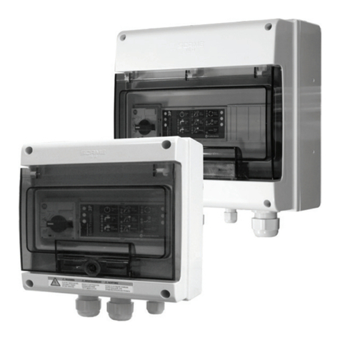
Franklin Electric SUBDRIVE CONNECT Series User manual

franklinwater.com
SUBDRIVE CONNECT
Installation and Operation Manual

2
COPYRIGHT INFORMATION
Copyright © 2019, Franklin Electric, Co., Inc. All rights reserved.
The entire contents of this publication are copyrighted under United States law and protected by worldwide copyright laws and treaty
provisions. No part of this material may be copied, reproduced, distributed, republished, downloaded, displayed, posted or transmitted
in any form by any means, including electronic, mechanical, photocopying, recording, or otherwise, without prior written permission of
Franklin Electric. You may download one copy of the publication from 35T35TUwww.franklinwater.comU35T onto a single computer for your personal,
non-commercial internal use only. This is a single copy, single use license, not a transfer of title, and is subject to the following restric-
tions: you may not modify the materials, use them for any commercial purpose, display them publicly, or remove any copyright or other
proprietary notices from them.
The information in this publication is provided for reference only and is subject to change without notice. While every effort has been
made to ensure the accuracy of this manual at the time of release, ongoing product improvements and updates can render copies obso-
lete. Refer to 35T35TUwww.franklinwater.comU35T for the current version.
This publication is provided “as is” without warranties of any kind, either express or implied. To the fullest extent possible pursuant to
applicable law, Franklin Electric disclaims all warranties, express or implied, including but not limited to, implied warranties of merchant-
ability, fitness for a particular purpose, and non-infringement of intellectual property rights or other violation of rights. Franklin Electric
does not warrant or make any representations regarding the use, validity, accuracy, or reliability of the material in this publication.
Under no circumstances, including but not limited to, negligence, shall Franklin Electric be liable for any direct, indirect, special, inciden-
tal, consequential, or other damages, including, but not limited to, loss of data, property damage, or expense arising from, or in any way
connected with, installation, operation, use, or maintenance of the product based on the material in this manual.
Trademarks used in this publication:
The trademarks, service marks, and logos used in this publication are registered and unregistered trademarks of Franklin Electric and
others. You are not granted, expressly, by implication, estoppel or otherwise, any license or right to use any trademark, service mark, or
logo displayed on this site, without the express written permission of Franklin Electric.
FE Logo and Design® and SubDrive Connect™ are registered trademarks of Franklin Electric.
NEMA is a trademark of The Association of Electrical Equipment and Medical Imaging Manufacturers.
Apple App Store™ is a service mark of Apple Inc.
iOS® is a registered trademark of Cisco Systems, Inc. and is used under license.
Google Play™ store is a trademark of Google LLC.
Android™ is a trademark of Google LLC.
Bluetooth is a registered trademark of Bluetooth SIG, Inc.
Modbus is a registered trademark of Schneider Electric USA, Inc.
Franklin Electric
Technical Publications
9255 Coverdale Road
Fort Wayne, IN 46809

TABLE OF CONTENTS
3
TABLE OF CONTENTS
PRODUCT INFORMATION - - - - - - - - - - - - - - - - - - - - - - - - - - - - - - - - - - - - - 7
Description - - - - - - - - - - - - - - - - - - - - - - - - - - - - - - - - - - - - - - - - - - 7
Features - - - - - - - - - - - - - - - - - - - - - - - - - - - - - - - - - - - - - - - - - - - 7
Models - - - - - - - - - - - - - - - - - - - - - - - - - - - - - - - - - - - - - - - - - - - - 8
Applications - - - - - - - - - - - - - - - - - - - - - - - - - - - - - - - - - - - - - - - - - 8
Pump Sizing and Performance - - - - - - - - - - - - - - - - - - - - - - - - - - - - - - - - 9
Generator Sizing - - - - - - - - - - - - - - - - - - - - - - - - - - - - - - - - - - - - - - -10
PRELIMINARY INSPECTIONS - - - - - - - - - - - - - - - - - - - - - - - - - - - - - - - - - - - -10
What’s in the Box - - - - - - - - - - - - - - - - - - - - - - - - - - - - - - - - - - - - - - -10
Unpacking and Inspection - - - - - - - - - - - - - - - - - - - - - - - - - - - - - - - - - - -10
INSTALLATION AND SETUP - - - - - - - - - - - - - - - - - - - - - - - - - - - - - - - - - - - -11
Installation Process 11
Standard Submersible Constant Pressure System - - - - - - - - - - - - - - - - - - - - 12
Typical Surface Pressure Boosting Application - - - - - - - - - - - - - - - - - - - - - - 13
Minimum Pressure Tank and Supply Pipe Sizing - - - - - - - - - - - - - - - - - - - - - 14
Physical Installation - - - - - - - - - - - - - - - - - - - - - - - - - - - - - - - - - - - - - -15
Environmental Requirements - - - - - - - - - - - - - - - - - - - - - - - - - - - - - - 15
Drive Mounting - - - - - - - - - - - - - - - - - - - - - - - - - - - - - - - - - - - - 16
Electrical Installation - - - - - - - - - - - - - - - - - - - - - - - - - - - - - - - - - - - - -17
Wiring Guidelines - - - - - - - - - - - - - - - - - - - - - - - - - - - - - - - - - - - 17
High Voltage Wiring Connections - - - - - - - - - - - - - - - - - - - - - - - - - - - - 20
Control Circuit Connections - - - - - - - - - - - - - - - - - - - - - - - - - - - - - - - 22
Drive Configuration - - - - - - - - - - - - - - - - - - - - - - - - - - - - - - - - - - - - - 24
Basic Setup (DIP SW1 – Position 1) - - - - - - - - - - - - - - - - - - - - - - - - - - - 24
Motor Phase Selection (DIP SW1 – Position 2) - - - - - - - - - - - - - - - - - - - - - - 24
Motor Type Selection (DIP SW1 – Position 6) - - - - - - - - - - - - - - - - - - - - - - 25
Pressure Input Selection (DIP SW1 – Position 5) - - - - - - - - - - - - - - - - - - - - - 26
Performance Settings - - - - - - - - - - - - - - - - - - - - - - - - - - - - - - - - - 27
OPERATION - - - - - - - - - - - - - - - - - - - - - - - - - - - - - - - - - - - - - - - - - - - 29
Control Functions - - - - - - - - - - - - - - - - - - - - - - - - - - - - - - - - - - - - - - 29
Standard Constant Pressure Operation - - - - - - - - - - - - - - - - - - - - - - - - - 29
Moisture Sensor - - - - - - - - - - - - - - - - - - - - - - - - - - - - - - - - - - - - 29
Tank Fill, Drain, and Level Control (Float Switches) - - - - - - - - - - - - - - - - - - - 29
Monitoring Functions - - - - - - - - - - - - - - - - - - - - - - - - - - - - - - - - - - - - 30
Protection Features - - - - - - - - - - - - - - - - - - - - - - - - - - - - - - - - - - - - - 30
Power Factor Correction - - - - - - - - - - - - - - - - - - - - - - - - - - - - - - - - 30
Over Temperature Foldback - - - - - - - - - - - - - - - - - - - - - - - - - - - - - - 30
Motor Soft Start - - - - - - - - - - - - - - - - - - - - - - - - - - - - - - - - - - - - 30
Motor Overload Protection - - - - - - - - - - - - - - - - - - - - - - - - - - - - - - - 30
Broken Pipe Protection - - - - - - - - - - - - - - - - - - - - - - - - - - - - - - - - - 30
Adjustable Underload Off Time (App Only) - - - - - - - - - - - - - - - - - - - - - - - 30

TABLE OF CONTENTS
4
COMMUNICATIONS - - - - - - - - - - - - - - - - - - - - - - - - - - - - - - - - - - - - - - - 31
FE Connect Mobile Application - - - - - - - - - - - - - - - - - - - - - - - - - - - - - - - - 31
Setup Wi-Fi Connection - - - - - - - - - - - - - - - - - - - - - - - - - - - - - - - - - 31
Drive Configuration Using the FE Connect App - - - - - - - - - - - - - - - - - - - - - - 32
System Monitoring - - - - - - - - - - - - - - - - - - - - - - - - - - - - - - - - - - - 35
Logs - - - - - - - - - - - - - - - - - - - - - - - - - - - - - - - - - - - - - - - - - - 36
ADVANCED APPLICATION OPTIONS - - - - - - - - - - - - - - - - - - - - - - - - - - - - - - - 37
Drive Control Using an External Device (Auxiliary Input) - - - - - - - - - - - - - - - - - - 37
Duplex Alternator Feature - - - - - - - - - - - - - - - - - - - - - - - - - - - - - - - 38
MAINTENANCE - - - - - - - - - - - - - - - - - - - - - - - - - - - - - - - - - - - - - - - - - 39
Troubleshooting - - - - - - - - - - - - - - - - - - - - - - - - - - - - - - - - - - - - - - - 39
System Diagnostics Fault History - - - - - - - - - - - - - - - - - - - - - - - - - - - - 39
Diagnostic Fault Codes - - - - - - - - - - - - - - - - - - - - - - - - - - - - - - - - - 39
Symptom Based Troubleshooting - - - - - - - - - - - - - - - - - - - - - - - - - - - - 43
Periodic Maintenance - - - - - - - - - - - - - - - - - - - - - - - - - - - - - - - - - - - - 45
Battery Replacement - - - - - - - - - - - - - - - - - - - - - - - - - - - - - - - - - - 45
Fan Replacement - - - - - - - - - - - - - - - - - - - - - - - - - - - - - - - - - - - - 46
Enhanced Pressure Input Board Replacement - - - - - - - - - - - - - - - - - - - - - - 46
SPECIFICATIONS - - - - - - - - - - - - - - - - - - - - - - - - - - - - - - - - - - - - - - - - - 47
SubDrive 15 Connect/SubDrive 20 Connect - - - - - - - - - - - - - - - - - - - - - - - - - - 47
SubDrive 30 Connect/SubDrive 50 Connect - - - - - - - - - - - - - - - - - - - - - - - - - 48
Accessories - - - - - - - - - - - - - - - - - - - - - - - - - - - - - - - - - - - - - - - - - 49
Applicable Standards - - - - - - - - - - - - - - - - - - - - - - - - - - - - - - - - - - - - 50
STANDARD LIMITED WARRANTY - - - - - - - - - - - - - - - - - - - - - - - - - - - - - - - - - 51

SAFETY INSTRUCTIONS
Hazard Messages
5
SAFETY INSTRUCTIONS
Hazard Messages
This manual includes safety precautions and other important
information in the following formats:
IMPORTANT: Identifies information that controls correct assem-
bly and operation of the product.
NOTE: Identifies helpful or clarifying information.
This symbol alerts the user to the presence of dangerous
voltage inside the product that might cause harm or elec-
trical shock.
This symbol alerts the user to the presence of hot sur-
faces that might cause fire or personal injury.
Before Getting Started
This equipment should be installed and serviced by technically
qualified personnel who are familiar with the correct selection
and use of appropriate tools, equipment, and procedures. Failure
to comply with national and local electrical and plumbing codes
and within Franklin Electric recommendations may result in elec-
trical shock or fire hazard, unsatisfactory performance, or equip-
ment failure.
Read and follow instructions carefully to avoid injury and prop-
erty damage. Do not disassemble or repair unit unless described
in this manual.
Failure to follow installation or operation procedures and all
applicable codes may result in the following hazards:
Indicates an imminently hazardous situation
which, if not avoided, will result in death or
serious injury.
Indicates a potentially hazardous situation
which, if not avoided, could result in death or
serious injury.
Indicates a potentially hazardous situation
which, if not avoided, could result in minor or
moderate personal injury.
Indicates a potentially hazardous situation
which, if not avoided could result in damage to
equipment or other property.
High voltages capable of causing severe
injury or death by electrical shock are
present in this unit.
• To reduce risk of electrical shock, disconnect power before
working on or around the system. More than one discon-
nect switch may be required to de-energize the equipment
before servicing.
• Make sure the ground terminal is connected to the motor,
control enclosures, metal plumbing, and other metal near
the motor or cable using wire no smaller than motor cable
wires.
Risk of bodily injury, electric shock,
or property damage.
• This equipment must not be used by children or persons
with reduced physical, sensory or mental abilities, or lack-
ing in experience and expertise, unless supervised or
instructed. Children may not use the equipment, nor may
they play with the unit or in the immediate vicinity.
• Equipment can start automatically. Lockout-Tagout before
servicing equipment.
• Operation of this equipment requires detailed installation
and operation instructions provided in this manual for use
with this product.
• Read entire manual before starting installation and opera-
tion.
• End User should receive and retain manual for future use.
• Keep safety labels clean and in good condition.
• Keep work area clean, well-lit, and uncluttered.

SAFETY INSTRUCTIONS
Product Specific Precautions
6
Product Specific Precautions Declarations
Wi-Fi Module
The Wi-Fi module has been tested and found to comply with part
15 of FCC Rules. These limits are designed to provide reasonable
protection against harmful interference. This equipment gener-
ates, uses, and can radiate radio frequency energy for limited
periods (approx. 15 min.) and, if the drive is not installed and used
in accordance with the instructions, may cause harmful interfer-
ence to radio communications. However, there is no guarantee
that interference will not occur in a particular installation. If this
equipment does cause harmful interference to radio or television
reception, which can be determined by turning the equipment off
and on, the user is encouraged to try to correct the interference
by one or more of the following measures:
• Reorient or relocate the receiving antenna.
• Increase the separation between the equipment and
receiver.
• Connect the equipment into an outlet on a circuit different
from that to which the receiver is connected.
• Consult the dealer or an experienced radio/TV technician for
help.
High voltages capable of causing severe
injury or death by electrical shock are
present in this unit.
• To minimize risk of electrical shock, disconnect power
before working on or around the system.
• Serious or fatal electrical shock may result from failure to
connect the ground terminal to the motor, drive, metal
plumbing, or other metal near the motor or cable, using
wire no smaller than motor cable wires.
• Do not remove VFD cover for wiring or periodic inspec-
tions while power is applied, or the unit is in operation.
• Capacitors inside the drive can still hold lethal voltage
even after power has been disconnected—ALLOW 5 MIN-
UTES FOR DANGEROUS INTERNAL VOLTAGE TO DIS-
CHARGE BEFORE REMOVING COVER.
• Operate VFD and control devices with dry hands.
• Do not use VFD if power or motor cable is damaged.
• Do not apply power to a damaged VFD or to VFD with
missing parts.
• Perform wiring after VFD has been mounted. Otherwise,
electric shock or bodily injury can occur.
Risk of damage to drive or other equipment.
• Install and wire VFD according to the instructions in this
manual.
• Take protective measures against ESD (Electrostatic Dis-
charge) before touching control boards during inspection,
installation or repair.
• This product is recommended for use with Franklin Electric
4-inch submersible motors as specified in this manual
(Refer to “Applications” on page 8). Use of this unit with
any other Franklin Electric motor or with motors from
other manufacturers may result in damage to both motor
and electronics.
• In applications where water delivery is critical, a replace-
ment pressure sensor and/or back-up system should be
readily available if the drive fails to operate as intended.

PRODUCT INFORMATION
Description
7
PRODUCT INFORMATION
Description
The Franklin Electric SubDrive Connect product family includes variable frequency drives (VFD) designed to
control and protect 3-wire, single- or three-phase motors, enhancing pump performance for residential and
light commercial water system applications. When used with Franklin Electric motors, the SubDrive Connect
drives a motor and pump at variable speeds to maintain constant water pressure, even as user demands
(water flow) change.
The SubDrive Connect series provides the capability to use a three-phase
motor with single-phase incoming power, which adds new efficiency and
quiet performance to rural homes and businesses.
Features
Configuration
• Compatible with submersible and surface pumps and motors
• Three-phase operation allows enhanced water delivery performance
using a smaller pump with a standard rated motor
• No programming required with easy DIP switch setup
• Built-in Duplex Alternator for Lead/Lag pump operation
• Works with small pressure tanks or existing larger tanks
Operation
• Easy-to-read LCD display for system status identification
• User-defined motor frequency range
• Auxiliary control input allows for additional external control
• Run and alarm relays provide switching for external monitors or systems
• Active Power Factor Correction (PFC) reduces average current used by
the drive
• Advanced filtering to remove radio frequency interference
Protection
• Protection against short circuit, under-load, overheat, under-voltage, surges, open circuit
• Broken-pipe detection
• User-defined under-load sensitivity and off time
• Ground Fault Protection for motor output
• Moisture Sensor input stops pump when water is detected
• Soft-start feature prevents water hammer and increases motor life
Communication
• The FE Connect mobile app can be used to adjust advanced settings, monitor drive characteristics, and
view fault history

PRODUCT INFORMATION
Models
8
Models
SubDrive Connect Models
Applications
Three-Phase Submersible Applications
Refer to “Pump Sizing and Performance” on page 9 when selecting a pump.
Motor and pump HP are programmed through DIP switch settings. Refer to “Submersible Motor and Pump
Sizes (DIP SW2 & DIP SW3)” on page 25.
Single-Phase (3-Wire) Submersible Applications
Model Part Number Model Part Number
SubDrive 50 5870205503C SubDrive 20 5870205303C
SubDrive 30 5870205403C SubDrive 15 5870205103C
Motor and Pump Combinations SubDrive 50 SubDrive 30 SubDrive 20 SubDrive 15
1.0 hp (0.75 kW) 234513-series motor with:
• 0.5 hp (0.37 kW),
• 0.75 hp (0.55 kW), or
• 1.0 hp (0.75 kW) pump
1.5 hp (1.1 kW) 234514-series motor with:
• 0.75 hp (0.55 kW),
• 1.0 hp (0.75 kW), or
• 1.5 hp (1.1 kW) pump
2.0 hp (1.5 kW) 234315-series motor with:
• 1.0 hp (0.75 kW),
• 1.5 hp (1.1 kW), or
• 2.0 hp (1.5 kW) pump
3.0 hp (2.2 kW) 234316-series motor with:
• 1.5 hp (1.1 kW),
• 2.0 hp (1.5 kW), or
• 3.0 hp (2.2 kW) pump
5.0 hp (3.7 kW) 234317-series motor with:
• 3.0 hp (2.2 kW), or
• 5.0 hp (3.7 kW) pump
Motor and Pump Combinations SubDrive 50 SubDrive 30 SubDrive 20 SubDrive 15
0.5 hp (0.37 kW) 214505-series motor with:
• 0.5 hp (0.37 kW) pump
0.75 hp (0.55 kW) 214507-series motor with:
• 0.75 hp (0.55 kW) pump
1.0 hp (0.75 kW) 214508-series motor with:
• 1.0 hp (0.75 kW) pump
1.5 hp (1.1 kW) 224300-series motor with:
• 1.5 hp (1.1 kW) pump
2.0 hp (1.5 kW) 224301-series motor with:
• 2.0 hp (1.5 kW) pump
3.0 hp (2.2 kW) 224302-series motor with:
• 3.0 hp (2.2 kW) pump

PRODUCT INFORMATION
Pump Sizing and Performance
9
SubDrive Connect Models with Surface Motor Capacity Ratings
SubDrive Connect models will operate many Franklin Electric surface mounted pumps, including VR, MH,
BT4, and DDS series.
NOTE: Recommended for use on inverter duty rated motors. Follow motor manufacturer recommendations
for cable lengths when using variable frequency drives.
When operating a surface system, drives are configured based on motor current capacity rather than horse-
power. Motor current capacity is programmed through DIP switch settings. Refer to “System Response (DIP
SW3)” on page 27.
NOTE: Using the FE Connect Mobile App, motor overload current can be set from 2.0 A up to the max cur-
rent rating of the drive model in 0.1 A increments. Refer to “Drive Configuration Using the FE Connect App”
on page 32.
Pump Sizing and Performance
SubDrive Connect models are capable of driving a smaller
pump than the motor horsepower rating to a similar or
better performance than a conventionally matched pump
and motor. This has the effect of extending the perfor-
mance curve of the overall system at both low and high
flow rates. See the example at right.
To select the proper pump for your application, first
choose the conventionally matched pump and motor
combination that meets the head and flow requirements.
Refer to the Franklin Electric AIM Manual.
Then, select an appropriate smaller pump from the same
pump series (flow rating) that works with your SubDrive
Connect model.
Refer to “Applications” on page 8.
The motor and pump sizes must be configured using DIP
switch settings on the SubDrive Connect.
Refer to “Submersible Motor and Pump Sizes (DIP SW2 & DIP SW3)” on page 25.
Model Current Capacity
SubDrive15 2.0 – 5.9 A, 230 VAC three-phase
SubDrive20 2.0 – 8.1 A, 230 VAC three-phase
SubDrive30 2.0 – 10.9 A, 230 VAC three-phase
SubDrive50 2.0– 17.8 A, 230 VAC three-phase

PRELIMINARY INSPECTIONS
Generator Sizing
10
Generator Sizing
Basic generator sizing for the SubDrive Connect system is 1.5 times the maximum input watts consumed by
the drive, rounded up to the next normal-sized generator.
Recommended minimum generator sizes:
IMPORTANT: Do not use with a Ground Fault Circuit Interrupter (GFCI). If using an externally regulated gen-
erator, verify that the voltage, hertz, and idle speed are appropriate to supply the drive.
PRELIMINARY INSPECTIONS
What’s in the Box
1. Variable Frequency Drive (VFD)
2. Pressure Transducer
3. Transducer Cable
4. Screwdriver/Adjustment Tool
5. Strain Relief Fitting
6. Installation Guide
Unpacking and Inspection
1. Inspect exterior of package for shipping damage. If there is damage, notify the shipping agent and your
sales representative.
2. Verify the part number and product ratings on the identification label are correct.
3. Remove VFD from the box and check for damage.
4. Remove the VFD cover and check part number, current rating, and nominal voltage on the sticker
attached to the side of the VFD. Make sure the electrical and environmental ratings are correct and ade-
quate for the application.
Model Generator Model Generator
SubDrive 15 3500 Watts SubDrive 30 7000 Watts
SubDrive 20 5700 Watts SubDrive 50 11000 Watts

INSTALLATION AND SETUP
Installation Process
11
INSTALLATION AND SETUP
Installation Process
Refer to the following table when planning installation of the SubDrive Connect.
1. The planned usage of the overall system will determine which options and control methods are appro-
priate, as well as how the VFD should be installed and programmed. Refer to the following pages for
examples of how the system might be used.
2. System options define and automate features that support the intended operation. These features may
require specialized control methods and programming. For more details, refer to “Drive Configuration”
on page 24, and “Advanced Application Options” on page 37.
3. The SubDrive Connect supports several methods for automating pump motor speed control. Refer to
“Drive Configuration” on page 24 for possible control setups.
4. The overall function of the system directly affects where and how the VFD should be mounted. Refer to
“Physical Installation” on page 15 for guidelines.
5. The selected motor application, along with the control method(s), determines how the VFD should be
connected. Refer to “Electrical Installation” on page 17 for more information.
6. The VFD can be quickly and easily programmed for most standard operations. Refer to “Drive Configu-
ration” on page 24. Advanced features or options may require additional adjustments to achieve the
desired performance. Refer to “Advanced Application Options” on page 37 and to “Drive Configuration
Using the FE Connect App” on page 32.
1 2 3 4 5 6
Plan System Goals Identify
Options
Select Control
Methods
Install VFD
Hardware
Install Wiring Program
Parameters
Intended Function
• Constant
pressure water
systems
• Pressure
Boosting
Hardware
Application
• Submersible
• Surface pump
• Single- or Three-
Phase
Automation
• Bump mode
• Steady Flow
• Drawdown
Protection
• Overload
• Underload
• Motor Ground
Fault
• Moisture Sensor
• Drive
Temperature
Multi-Pump
• Duplex
Alternator
• Lead/Lag
Pressure Feedback
Type
• Transducer
• Pressure Sensor
Switches
• Float
• On/Off
Potentiometer
• Setpoint value
• Underload
Sensitivity
Communications
• Drive-to-drive
• Aux Input
Location
• Inside
• Outside
Climate control
• Temperature
• Moisture
Distance
• Wire sizes
• Filtering
requirements
Measurements
• Clearance
• Drilling
Conduit
• Routing
• Separation
High Voltage
• Grounding
• Inputs
• Outputs
Control circuits
• Feedback inputs
• Relay outputs
• Communications
Basic
• Application
• Motor ratings
• Setpoints
I/O setup
• Input functions
• Output
functions
Option settings
• Enable features

INSTALLATION AND SETUP
Installation Process
12
Standard Submersible Constant Pressure System
The above drawing illustrates how a typical submersible pump system should be arranged for a constant
pressure application.
1. Pump and Franklin Electric Motor. Refer to the Franklin Electric AIM Manual for pump, pipe, and cable
sizing information.
2. Check Valve
3. Pressure Relief Valve: Pressure relief valve must be able to pass full pump flow at 100 PSI.
4. Pressure Tank: Refer to “Minimum Pressure Tank and Supply Pipe Sizing” on page 14.
5. Pressure Gauge
6. Pressure Transducer or Sensor: Install in a vertical position.
7. SubDrive Connect VFD
8. Power Supply from Circuit Breaker: Single phase, 208/230 VAC +/- 10%.
9. Power to Motor: Single phase or Three-Phase
A tank tee is recommended for mounting the tank, pressure transducer, pressure gauge, and pressure relief
valve. If a tank tee is not used, the pressure transducer or pressure sensor should be within 6 feet (1.8
meters) of the pressure tank to minimize pressure fluctuations. There should be no elbows between the tank
and pressure transducer or pressure sensor.
Risk of bodily injury or property damage.
• Pumps can develop very high pressure in some situations. Always install a pressure relief valve able
to pass full pump flow at 100 psi.
• Install the pressure relief valve near the pressure tank and route to a drain capable of full system flow.

INSTALLATION AND SETUP
Installation Process
13
Typical Surface Pressure Boosting Application
The above drawing illustrates how a typical surface mounted pump system should be arranged for a pres-
sure boosting application.
1. Water Supply
2. Check Valve
3. Ball Valve
4. Pressure Relief Valve: Pressure relief valve must be able to pass full pump flow at 100 PSI.
5. Pressure Tank. Refer to “Minimum Pressure Tank and Supply Pipe Sizing” on page 14.
6. Pressure Gauge
7. Pressure Transducer or Sensor: Locate within 5 feet (1.5 m) of pump discharge. Install in a vertical
position.
8. SubDrive Connect VFD
9. Power Supply from Circuit Breaker. Single phase, 208/230 VAC +/- 10%.
10. Power to Motor: Three-Phase.
11. Optional Bypass: For system maintenance.
IMPORTANT: If the pump is equipped with a built-in pressure switch, the power wires from the VFD must
bypass the pressure switch and connect directly to the motor.
Risk of bodily injury or property damage.
• Pumps can develop very high pressure in some situations. Always install a pressure relief valve able
to pass full pump flow at 100 psi.
• Install the pressure relief valve near the pressure tank and route to a drain capable of full system flow.

INSTALLATION AND SETUP
Installation Process
14
Minimum Pressure Tank and Supply Pipe Sizing
A VFD system needs only a small pressure tank to maintain constant pressure, although a larger tank may
be used. If adding a SubDrive Connect to a conventional system with an existing large tank, refer to
“Advanced Options” on page 34.
When using a standard pressure sensor, system performance can be adjusted using the FE Connect mobile
app to select tank size. Refer to “Advanced Options” on page 34.
The pressure tank pre-charge setting should be 70% of the targeted system pressure. To check the tank’s
pre-charge, de-pressurize the water system by opening a tap with the drive off. Measure with a pressure
gauge at the inflation valve and make any necessary adjustments.
Refer to the following recommendations for best performance.
Submersible Pump Applications
Surface Pump Applications
Minimum Supply Pipe Sizes
The minimum supply pipe diameter past the pressure sensor (transducer) should be selected not to exceed
a maximum velocity of 8 feet per second (2.4 m/s) based on the flow rate of the system.
Pump Flow Rating VFD Model Minimum Tank Size
Less than 12 gpm (45.4 lpm)
SubDrive 15 2 gallons (7.6 liters)
SubDrive 20 4 gallons (15.1 liters)
SubDrive 30 4 gallons (15.1 liters)
SubDrive 50 8 gallons (30.3 liters)
12 gpm (45.4 lpm) and higher
SubDrive 15 4 gallons (15.1 liters)
SubDrive 20 8 gallons (30.3 liters)
SubDrive 30 8 gallons (30.3 liters)
SubDrive 50 20 gallons (75.7 liters)
Maximum Pump Flow Minimum Tank Size
10 GPM 2 gallons (7.6 liters)
20 GPM 4 gallons (15.1 liters)
30 GPM 4 gallons (15.1 liters)
40 GPM 8 gallons (30.3 liters)
Maximum GPM (lpm) Minimum Pipe Diameter
11.0 (41.6) 3/4”
19.6 (74.2) 1”
30.6 (115.8) 1-1/4”
44.1 (166.9) 1-1/2”
78.3 (296.4) 2”
176.3 (667.4) 2-1/2”

INSTALLATION AND SETUP
Physical Installation
15
Physical Installation
Environmental Requirements
The drive is intended for operation in ambient temperatures from -13 °F to 122 °F (-25 °C to 50 °C). Use the
following recommendations when selecting a location to mount the drive:
• The unit should be mounted on a structure such as a wall or post
capable of supporting the weight of the unit.
• The drive electronics are air-cooled. Allow at least 6 inches (15.24
cm) of clearance on each side and below the unit for air flow.
• The mounting location should have access to 208/230 VAC elec-
trical supply and to the motor wiring. To avoid possible interfer-
ence with other appliances, refer to “Cable Routing” on page 17.
Special Considerations for Outdoor Use
The drive is suitable for outdoor use with a NEMA 3R rating; however,
the following considerations should be made when installing the con-
troller outdoors:
• The unit must be mounted vertically with the wiring end oriented
downward, and the cover must be properly secured (also applies
to indoor installations).
• Mount the drive on a surface or back plate no smaller than the
outer dimensions of the enclosure.
• NEMA 3R enclosures are capable of withstanding downward-
directed rain only. Protect from hose-directed or sprayed water
as well as blowing rain. Failure to do so may result in controller
failure.
• Install away from direct sunlight or locations subject to extreme
temperatures or humidity.
• Use appropriate screening for the air inlet and outlet when installed in areas where insect or small ani-
mal intrusion is an issue. Refer to “Accessories” on page 49 for ordering information.
• Screens should be cleaned on a regular basis to ensure proper airflow.
Risk of damage to Drive, or malfunction can occur due to improper handling,
installation, or environment.
• Handle with care to prevent damage to the plastic components.
• Do not mount VFD on equipment with excessive vibration.
• Install in a location where temperature is within the range of product rating.
• Mount VFD vertically (top up) for proper heat dissipation.
• Do not mount VFD in direct sunlight or near other heat sources.
• Do not install in corrosive environments.
• Installation of non-approved screening may damage the drive and/or reduce output.

INSTALLATION AND SETUP
Physical Installation
16
Drive Mounting
The drive should be mounted on a surface or backplate no smaller than the outer controller dimensions in
order to maintain the NEMA 3R rating. The controller must be mounted at least 18" (45.7 cm) off the ground.
The drive is mounted using the hanging tab on the top side of the enclosure, as well as two (2) additional
mounting holes on the back side. All three (3) screw hole locations should be used to ensure the drive is
securely mounted.
IMPORTANT: Do not drill holes in the drive.
Model “A” “B” “C” “D” “E”
SubDrive 15, 464.2 mm
(18.28 in)
355.2 mm
(13.98 in)
454.7 mm
(17.90 in)
427.4 mm
(16.83 in)
157.4 mm
(6.19 in)
SubDrive 20,
SubDrive 30,
539.4 mm
(21.24 in)
430.4 mm
(16.94 in)
529.9 mm
(20.86 in)
502.6 mm
(19.79 in)
157.4 mm
(6.19 in)
SubDrive 50 539.4 mm
(21.24 in)
430.4 mm
(16.94 in)
529.9 mm
(20.86 in)
416.2 mm
(16.39 in)
168.4 mm
(6.63 in)

INSTALLATION AND SETUP
Electrical Installation
17
Electrical Installation
Wiring Guidelines
Follow the recommendations in this section to ensure best performance of the drive and to avoid interfer-
ence with other devices.
Cable Routing
Use the above diagram as a guide when routing wiring to VFD.
1. Mount the drive as close as possible to the service entrance panel. Wire directly to the service entrance.
Do not connect to a sub-panel.
2. Use a dedicated branch circuit for the drive. Refer to “Fuse/Circuit Breaker and Wire Sizing” on page 18.
3. Route motor wiring out of building as soon as possible. Separate input power and motor wiring by at
least 8 in. (20.3 cm). Refer to “Maximum Motor Cable Length” on page 19.
4. Cross over other branch circuits and facility wiring at a 90 angle. If it is necessary to run wiring in par-
allel, separate by at least 8 in. (20.3 cm).
All control wiring—sensors, switches, transducers, etc.—should be in a separate conduit routed individually,
not parallel, from high voltage wiring. In addition, any shielded cables should be properly grounded.

INSTALLATION AND SETUP
Electrical Installation
18
Branch Circuit Protection
Integral solid state short circuit protection does not provide branch circuit protection. Branch circuit protec-
tion must be provided in accordance with the National Electrical Code and any additional local codes, or the
equivalent. Drive shall be protected by fuse or inverse-time circuit breaker only, rated 300 V, and a maxi-
mum 300% of full load motor output current rating as noted below.
Fuse/Circuit Breaker and Wire Sizing
1 Based on a 3% voltage drop.
* 90 C Insulation only.
NOTE: Minimum breaker amps may vary from AIM Manual specifications because of VFD characteristics.
Risk of damage to VFD, or malfunction can occur.
Follow all wire routing and grounding instructions carefully. Inductive currents caused by parallel wiring,
or close proximity between high voltage and control wiring can cause unexpected behaviors.
• Do not run input power and motor wires in the same conduit.
• Do not run motor wires from multiple VFDs in common conduit.
• Do not run control wiring parallel with high voltage wiring.
• Do not install a magnetic contactor or disconnect in the motor circuit.
• Do not run VFD wiring parallel with house or out-building wiring.
• Do not use aluminum wires for VFD connections.
• Do not use with a Ground Fault Circuit Interrupter (GFCI).
• All wiring must comply with the National Electrical Code and local codes.
• Improper splicing or damage to motor cable insulation may expose the conductor(s) to moisture and
can produce motor cable failure.
Model Input
Voltage Fuse/Breaker
Amps AWG Copper Wire Sizes, 75° C Insulation, and Panel to Drive Cable Lengths (in feet)1
14 12 10 8 6 4 3 2 1 1/0 2/0
SubDrive 15 208
230
15
15
70*
85
110
135
185
225
280
345
450
550
710
865
880
1075
1160
1415
1465
1795
–
–
–
–
SubDrive 20 208
230
20
20
–
–
–
85*115
140
180
220
285
345
450
550
555
680
730
895
925
1130
–
–
–
–
SubDrive 30 208
230
25
25
–
–
–
–
95*
115*145
180
235
285
370
455
460
560
605
740
765
935
–
–
–
–
SubDrive 50 208
230
40
40
–
–
–
–
–
–
–
115*150
185
235
290
295
360
385
470
490
600
610
745
735
895

INSTALLATION AND SETUP
Electrical Installation
19
Maximum Motor Cable Length
NOTE:
• The use of 600 V minimum rated motor cable is required.
• SubDrive models show cable lengths for highest power motor supported by each model. Refer to the
Franklin Electric AIM Manual when using a smaller motor.
• Maximum allowable wire lengths are measured between the controller and motor.
• Flat-jacketed submersible motor cable is recommended. All splices in the motor cable must be properly
sealed with watertight shrink tubing. Use extreme caution to avoid damaging or compromising the
motor cable insulation during installation or service.
Conduit Locations and Sizing
Use appropriate strain relief or conduit connectors.
1. Incoming power supply—Hole = 0.88 in. (22.2 mm), Knockout = 1.13 in. (28.6 mm)
2. Power output to motor—Hole = 1.13 in (28.6 mm), Knockout = 1.37 in. (34.9 mm)
3. Control wiring (transducer/sensor) input—Hole = 0.5 in. (12.7 mm)
4. Optional cabling for auxiliary controls—Knockout = 0.88 in. (22.2 mm)
Model Motor Family Horsepower AWG 600V Copper Wire Sizes, 75° C Insulation, and Motor Cable Lengths (in feet)
14 12 10 8 6 4
SubDrive 15 234 514 xxxx 1.5 (1.1 kW) 420 670 1060 – – –
SubDrive 20 234 315 xxxx 2.0 (1.5 kW) 320 510 810 1000 – –
SubDrive 30 234 316 xxxx 3.0 (2.2 kW) 240 390 620 990 – –
SubDrive 50 234 317 xxxx 5.0 (3.7 kW) – 230 370 590 920 –

INSTALLATION AND SETUP
Electrical Installation
20
High Voltage Wiring Connections
Ground Connections
Follow these grounding requirements to ensure safety and performance.
1. Make sure a service entrance ground rod is properly installed and connected.
2. Service Entrance Panel.
3. An input power ground wire from the supply panel must be connected to the drive.
4. A dedicated output ground wire from the drive must be connected to the motor. Motor and ground
wires must be bundled together.
Contact with hazardous voltage could result in death or serious injury.
• Disconnect and lock out all power before installing or servicing equipment.
• Connect the motor, the drive, metal plumbing, and all other metal near the motor or cable to the
power supply ground terminal using wire no smaller than motor cable wires.
• Install and wire in accordance with all applicable local and national electrical construction codes.
Risk of damage to drive, or malfunction can occur.
• Ensure that the system is properly grounded all the way to the service entrance panel. Improper
grounding may result in loss of voltage surge protection and interference filtering.
This manual suits for next models
4
Table of contents
Languages:
Other Franklin Electric Control Unit manuals
Popular Control Unit manuals by other brands

Allen-Bradley
Allen-Bradley ArmorBlock 1732E-IT4IM12R installation instructions

Spirax Sarco
Spirax Sarco TD3-3 Installation and maintenance instructions

Lucent Technologies
Lucent Technologies Stinger STGR-LIM-AD-48 Guide

Nibe
Nibe MODBUS 40 Installer manual

WAGO
WAGO I/O-SYSTEM 751-4001 manual

HABONIM
HABONIM 24/H24 Series Installation, Operating, Maintenance