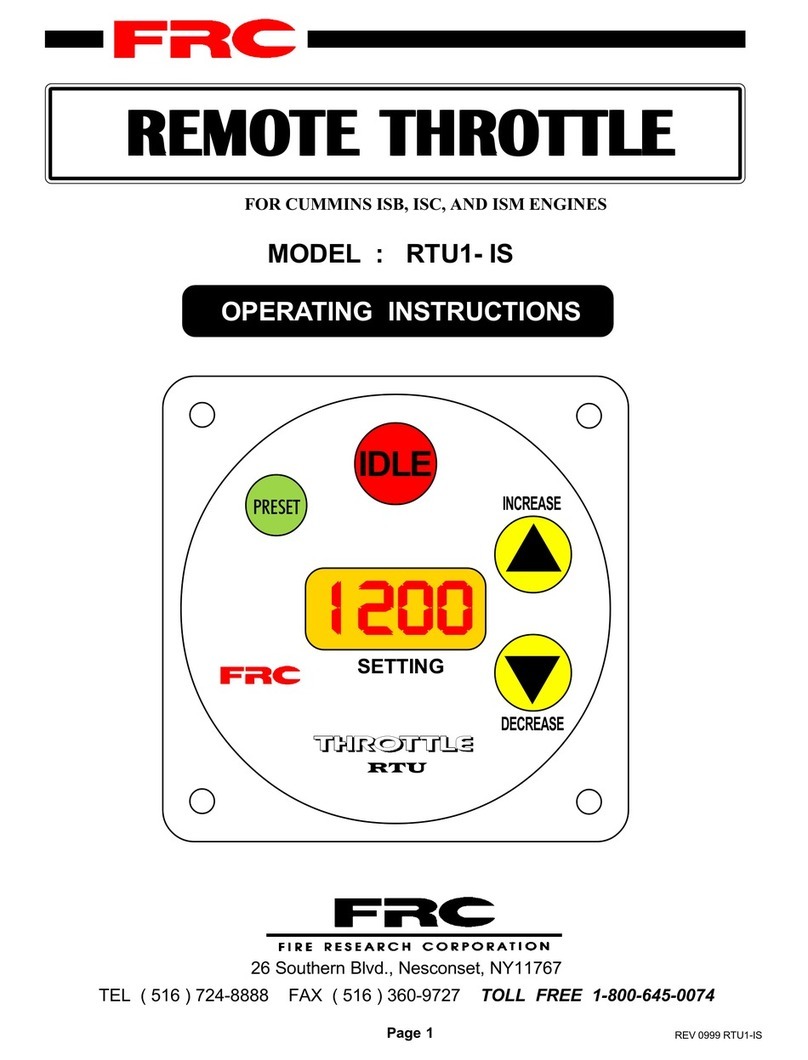
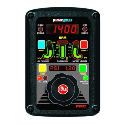
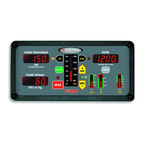
FRC PRO-S 1 User manual

PRO-SRev1104
1
FIRE RESEARCH CORPORATION
http://www.fireresearch.com
26SouthernBlvd.,Nesconset,NY11767
TEL ( 631 ) 724-8888 FAX ( 631 ) 360-9727 TOLL FREE 1-800-645-0074
PRESSURE GOVERNOR

PRO-S Rev1104
2
CONTENTS Table of Contents
CONTENTS ............................................................................................................... 2
List of Tables ......................................................................................................... 3
List of Figures........................................................................................................ 3
INTRODUCTION...................................................................................................... 4
Overview ................................................................................................................ 4
Features.................................................................................................................. 4
Specifications......................................................................................................... 5
GENERAL DESCRIPTION....................................................................................... 7
Components .......................................................................................................... 7
Controls and Indicators ......................................................................................... 8
INSTALLATION ...................................................................................................... 10
Install Control Module ......................................................................................... 10
Install Pressure Transducer.................................................................................. 11
Install Throttle Servomotor (Non-Electronic Engine Only) ................................. 12
Install Optional High Idle ..................................................................................... 14
OPERATION............................................................................................................ 15
Pressure Mode Operation.................................................................................... 16
RPM Mode Operation ......................................................................................... 17
Change Preset Setting (Pressure or RPM)........................................................... 17
System Options ................................................................................................... 18
CALIBRATION........................................................................................................ 19
RPM Calibration (PRO-S 3, 6, and 8)................................................................. 19
High Idle Option Calibration................................................................................ 20
3rd Gear Lock-up RPM Calibration (Ford 6.0L) ................................................ 20
DIAGNOSTICS ....................................................................................................... 21
WIRING ................................................................................................................... 22
Power................................................................................................................... 22
HighIdle .............................................................................................................. 23
Pressure Transducer ............................................................................................ 24
Common OME Connectors ................................................................................ 25
Cummins PRO-S 1 Cables .................................................................................. 26
Cummins Harness Connections........................................................................... 27
Detroit Diesel (Series 50 and 60) PRO-S 2 Cables.............................................. 30
Detroit Diesel (Series 50 and 60) Harness Connections ...................................... 31
Non-Electronic Engine PRO-S 3 Cables ............................................................. 32
Non-Electronic Harness Connections.................................................................. 33
Navistar and Detroit Diesel (Series 40) PRO-S 4 Cables .................................... 34
Navistar and Detroit Diesel (Series 40) Harness Connections ............................. 35
Caterpillar PRO-S 5 Cables................................................................................. 36
Caterpillar Harness Connections.......................................................................... 37

PRO-SRev1104
3
List of Tables
Table 1. PRO-S Specifications.................................................................................. 5
Table 2. Pressure Transducer Output Voltage ........................................................... 6
Table 3. Diagnostic Codes....................................................................................... 21
List of Figures
Figure 1. Controls and Indicators .............................................................................. 9
Figure 2. Control Module Mounting Dimensions .................................................... 10
Figure 3. Pressure Transducer ................................................................................. 11
Figure 4. Fuel ControlArm...................................................................................... 12
Figure 5. Throttle Servo Motor................................................................................ 13
Figure 6. PRO-S Power Supply Wiring................................................................... 22
Figure 7. Optional High Idle Schematic ................................................................... 23
Figure 8. Pressure Transducer Wiring...................................................................... 24
Figure 9. Common OEM Connectors ..................................................................... 25
Figure 10. Cummins PRO-S 1 Wiring ..................................................................... 26
Figure 11. Detroit Diesel (Series 50 and 60) PRO-S 2 Wiring ................................. 30
Figure 12. Non-Electronic PRO-S 3 Wiring ............................................................ 32
Figure 13. Navistar and Detroit Diesel (Series 40) PRO-S 4 Wiring........................ 34
Figure 14. Caterpillar PRO-S 5 Wiring .................................................................... 36
Figure 15. Ford PRO-S 6 Wiring............................................................................. 40
Figure 16. Mack PRO-S 7 Wiring............................................................................ 46
Figure 17. Scania PRO-S 8 Wiring .......................................................................... 48
Figure 18. Mercedes PRO-S 10 Wiring ................................................................... 50
Figure 19. Flyback Diode Wiring............................................................................. 52
Ford PRO-S 6 Cables ......................................................................................... 40
Ford Harness Connections .................................................................................. 41
FordAdapter and Cable Detail (6.0 L Engines)................................................... 43
Ford Torque Lock-up Module (6.0 L Engines) ................................................... 44
Mack PRO-S 7 Cables ........................................................................................ 46
Mack Harness Connections................................................................................. 47
Scania PRO-S 8 Cables....................................................................................... 48
Scania Harness Connections ............................................................................... 49
Mercedes PRO-S 10 Cables................................................................................ 50
Mercedes Harness Connections .......................................................................... 51
FLYBACK DIODE WIRING................................................................................... 52

PRO-S Rev1104
4
INTRODUCTION
Overview
The Fire Research PRO-S pressure governor uses state of the art programmable
microprocessor technology. It will maintain a steady pump discharge pressure by
controlling the engine speed or maintain a selected engine RPM. The PRO-S will
operate in one of two modes, pressure or RPM.
In pressure mode the PRO-S maintains a constant pump discharge pressure. The
discharge pressure is monitored and compared to the selected pressure setting, the
engine RPM is varied to keep the discharge pressure at the selected setting.
In RPM mode the PRO-S maintains a constant engine RPM. The pump discharge
pressure is monitored, it can vary but will be limited to an increase of 30 PSI. If the
discharge pressure increases 30 PSI, the pressure governor will automatically lower
the engine RPM to reduce the discharge pressure.
All controls and indicators are located on the front of the control module.
Features
Power Up in Pressure Mode
Automatic Regulation of Pump Discharge Pressure
Manual Control of Pressure or Engine RPM Settings
Field Programmable Presets
DiagnosticCapabilities
No Pressure or RPM Variation When Changing Modes
Limits Increase of Pressure When in RPM Mode
Recognition of No Water Condition With Automatic Response
Interlock Signal Recognition
Return to Engine Idle With the Push of a Button
High Idle Kit (Optional)
24 VDC (Optional)
KPa (Optional)

PRO-SRev1104
5
Specifications
The PRO-S is available in various models. Each model is programmed to interface
with specific engines. All models provide the same functions, push button controls,
and digital readout for the management of pump discharge pressure. (Refer to Table 1
for detailed specifications.)
Table 1. PRO-S Specifications
Note1:24 VDCOptional
PRO-S 1 PRO-S 2 PRO-S 3 PRO-S 4 PRO-S 5 PRO-S 6 PRO-S 7 PRO-S 8 PRO-S 1
0
ENGINE Cummins
(IS Series)
Detroit Diesel
(Series 50 and
60)
Non-
Electronic
Navistar and
Detroit Diesel
(Series 40) Caterpillar Ford Mack Scania Mercede
s
SUPPLY
VOLTAGE
(See Note 1)
12 VDC 12 VDC 12 VDC 12 VDC 12 VDC 12 VDC 12 VDC 12 VDC 12 VDC
SUPPLY
CURRENT 1.0 AMP 1.0 AMP 3.0 AMP 1.0 AMP 1.0 AMP 1.0 AMP 1.0 AMP 1.0 AMP 1.0 AMP
RESPONSE
(Idle to full
governed speed)
5 SEC 5 SEC 30 SEC 5 SEC 5 SEC 5 SEC 5 SEC 5 SEC 5 SEC
RECOVERY
(After open or
close of valve)
1.5 SEC 1.5 SEC 1.5 SEC 1.5 SEC 1.5 SEC 1.5 SEC 1.5 SEC 1.5 SEC 1.5 SEC
RPM
CALIBRATION None None Manual None None Manual None Manual None
DATALINK
PROTOCOL J1587 J1587 J1587 J1587 J1587 J1587

PRO-S Rev1104
6
Table 2. Pressure Transducer Output Voltage
PRESSURE
(PSI) VOLTAGE
(VDC)
00.5
100 1.917
150 2.625
200 3.33
250 4.04
300 4.75
Pressure Transducer
ModelNumber: PRO31PT2
Pressure Range: 0 - 300 PSI
Proof Pressure: 800 PSI
ExcitationVoltage: 5 VDC
OutputVoltage: 0.5 - 4.75 VDC
(See Table 2)

PRO-SRev1104
7
GENERAL DESCRIPTION
The PRO-S pressure governors are compatible with the following engines:
PRO-S 1 Cummins ISB, ISC, ISM, and ISL
PRO-S 2 Detroit Diesel (Series 50 and 60)
PRO-S 3 Non-Electronic diesel and gasoline
PRO-S 4 Navistar and Detroit Diesel (Series 40)
PRO-S 5 Caterpillar PRO-S 6 Ford
PRO-S 7 Mack PRO-S 8 Scania
PRO-S 10 Mercedes
Components
The PRO-S pressure governors consists of the following components:
Control Module
Pressure Transducer
Throttle Servomotor (Non-electronic engines only.)
High Idle Kit (Optional)
Cables
Control Module
The pressure governor control module is waterproof and has dimensions of 4.25
inches high by 4.25 inches wide by 3.5 inches deep (4.5 inches deep on non-electronic
and 24 VDC units). All controls and indicators are located on the front of the control
module. (Refer to Controls and Indicators.)
Pressure Transducer
The pressure transducer is mounted on the pump discharge manifold. It provides
an input signal to the control module that is proportional to the discharge pressure.
Throttle Servomotor (Non-Electronic Engines Only)
The throttle servomotor is installed on engines that do not have electronic engine
control systems. It provides the mechanical connection between the control module
and the engine throttle. The travel of the linear actuator arm is 1.85 inches.
High Idle Kit (Optional)
The High Idle Kit provides the components to install this option including a DPDT
switch, 2500 ohm potentiometer, an indicator light, two diodes, and a cable.

PRO-S Rev1104
8
Controls and Indicators
Allcontrolsandindicatorsarelocatedonthefrontofthecontrolmodule.Itcontains
the push button electronic controls, LED indicators, and a digital display. (Refer to
Figure 1.)
PRESET Button
The green PRESET button sets the pump pressure or engine RPM to a
preprogrammed value. This button is also used in the programming of pressure or
RPM preset values.
IDLE Button
The red IDLE button immediately sets the engine to idle RPM. This button can be
used in an emergency or for a normal shut down after operations.
SETTING Display
The SETTING display will show a diagnostic error code, IdLE for engine idle,
the pressure setting or the RPM setting. The LED digital display has daylight bright
digits at least 0.56 inch high.
INCREASE Button
During operations the yellow INCREASE button raises pressure or RPM setting.
This button is also used in the programming of the pressure or RPM preset values.
DECREASE Button
During operations theyellow DECREASEbuttonlowerspressureorRPMsetting.
This button is also used in the programming of the pressure or RPM preset values.
RPM Button
The green RPM button selects the RPM mode of operation.
RPM LED
The red RPM LED is on to indicate operation in the RPM mode.
PRESSURE Button
The green PRESSURE button selects the pressure mode of operation.
PRESSURE LED
The amber PRESSURE LED is on to indicate operation in the pressure mode.

PRO-SRev1104
9
Figure 1. Controls and Indicators
PRESSURE
Button
DECREASE
Button
IDLE
Button
PRESET
Button
INCREASE
Button
SETTING
Display
RPM
Button
PRESSURE
LED RPM
LED

PRO-S Rev1104
10
INSTALLATION
Install Control Module
Note: The control module can be mounted anywhere on the pump panel. It
should be mounted close to the engine warning indicators.
1. Measure and mark mounting location for control module panel cutout and
mounting screw holes. Make sure there is clearance behind the panel for the
module and cables before cutting holes. Refer to Figure 2 for layout and
dimensions.
2. Cut out a 3.75-inch diameter hole and drill four holes for mounting screws.
3. Place control module in position and secure with four screws (10-32 mounting
hardware is recommended).
Note:If the optional remote high idle kit is not being installed, ensure that the
high idle cap (and pin B to pin C jumper wire) is installed on the end of the
control module high idle cable.
4. Connect cables at rear of the contol module. (Refer to Wiring section.)
Figure 2. Control Module Mounting Dimensions
Note:Non-electronic and 24 VDC
unitsare4.500".
Measurementsareininches.

PRO-SRev1104
11
Install Pressure Transducer
The discharge pressure transducer is mounted on the discharge manifold of the
pump.AT-fitting can be used to share the master pressure gauge outlet on the discharge
manifold.Ifthereisa check valveinthedischargeside of thepump,mountthetransducer
before the check valve.
Note: Install the pressure transducer upright so water in the end of the
pressure transducer is able to drain back into the pipe.
1. Screw the transducer into a 1/4-18 NPT hole.
Caution: Do not use the main body that houses the electronics to tighten the
pressure transducer. Damage to the transducer may occur.
2. Tighten the transducer with a 9/16-inch wrench on the lower hex fitting.
3. Connect the pressure transducer cable from the control module to the pressure
transducer. (Refer to Wiring section.)
Figure 3. Pressure Transducer
Caution: Do not use the main body
that houses the electronics to tighten
the transducer. Damage to the
transducer may occur.
1/4-18 NPT
1.02"
0.86"
1234567890
1234567890
1234567890
1234567890
1234567890
1234567890
1234567890
1234567890
1234567890
1234567890
1234567890
0.80"
Lower Hex
Fitting
Supply
Voltage
Signal
Output
Ground
1.04"
Main Body

PRO-S Rev1104
12
Figure 4. Fuel Control Arm
Install Throttle Servomotor (Non-Electronic Engine
Only)
The throttle servomotor (FRC part number PRO-34M.) is used for engines that
do not have an electronic engine control system.
The throttle servomotor has a universal mounting flange with six mounting holes.
It should be mounted in a location where vibration and high temperatures will be
minimized.
Note:The throttle cable (or linkage rod) varies for each installation and is not
supplied with the throttle servomotor.
Minimize Engine Oscillation
It is important to note that in order to minimize engine oscillations the stroke at the
point the cable attaches to the fuel control arm should be 2 inches.
The length of the stroke at the point the cable attaches to the fuel control arm has a
direct effect on the sensitivity of the system. The shorter the stroke, the more sensitive
the system. Most engine oscillations occur because this stroke distance is too short.
To increase the stroke distance, increase the length of the fuel control arm.
Note: Extending the effective
length of the fuel control arm will
increase the stroke distance and
decrease the sensitivity of the
system.
Throttle
Cable
Typical Fuel
ControlArm
Shorter
Stroke
LongerStroke

PRO-SRev1104
13
Installation
1. Place the throttle servomotor in position and secure.
Note: The total motion of the linear actuator rod is approximately 1.85
inches. The motion of the fuel control arm must be more than 1.85 inches
to prevent damage to the arm. It is recommended that the fuel control arm
have a two inch stroke at the point the cable attaches.
2. Connect the throttle cable to the linear actuator rod and the fuel control arm.
3. Test the motion of the fuel control arm by operating the servomotor linear
actuatorrodtoitsminimum and maximum positions.Ensurethatthefuelcontrol
arm operates freely. (Connect +12 VDC to red wire and ground to black wire
to extend actuator rod, reverse wires to retract rod.)
4. Connect the 2-pin connector to the servomotor cable. (Refer toWiring section.)
Figure 5. Throttle Servo Motor
Typical
Fuel
Control
Arm Set
Screw
INCREASE
Throttle
Cable 1.85"
Throw
MAX MIN
Throttle
Servo
Motor
Linear
Actuator
Rod
Mounting
Flange
Throttle
Cable
2"
Stroke
MIN MAX
Typical
Throttle Cable
and Support
Bracket
Throttle Servo Motor Cable
Connector
Pin/Wire Description
A/Red +12VDC toExtend
B/Black +12 VDC to Retract
Note: Extend refers to the INCREASE
direction as shown on the servo motor.
2-Pin
Packard
Connector
Note: The throttle cable is not
supplied with the throttle servomotor.

PRO-S Rev1104
14
Install Optional High Idle
TheHighIdleKit(FRCpartnumberPRO-38H) provides the necessary components
needed to install this option including a DPDT switch, 2500 ohm potentiometer, an
indicator light, two diodes, and a cable.
The high idle cap may be installed on the end of the control module high idle 3-pin
Deutsch connector. This cap is removed to install the high idle cable.
Note: Refer to the high idle calibration procedure after the installation is
complete to adjust the 2500 ohm potentiometer for high idle engine RPM.
Install the potentiometer in a location that will allow access to adjust it during the
calibration procedure.
For wiring of the high idle components refer to Figure 7. Optional High Idle
Schematic.

PRO-SRev1104
15
OPERATION
On power up the PRO-S will be in the pressure mode of operation. The SETTING
display will show IdLE. If there is a problem, the SETTING display will show an
error code. Refer to the Diagnostics section for error code descriptions.
The minimum pump discharge pressure must be greater than 15 PSI for
the PRO-S governor to take control of engine speed.
No variation in discharge pressure or RPM will occur when changing between
pressure and RPM modes.
INCREASE/DECREASE Buttons
The INCREASE and DECREASE buttons are used to change pressure and
RPM settings or program preset values. The rate and amount the numbers change
when a button is pressed depends on the mode and how long the button is held.
In Pressure Mode. Press either button momentarily to change the pressure setting
by 1 PSI. Press and hold the button for more than 2 seconds and the pressure
setting will change by 5 PSI twice and then by 10 PSI until the button is released.
In RPM Mode. Press either button momentarily to change the RPM setting by
10 RPM. Press and hold the button for more than 2 seconds and the RPM
setting will change by 50 RPM twice and then by 100 RPM until the button is
released.
Switching Between Operating Modes
• No variation in discharge pressure or RPM will occur when changing between
pressure and RPM modes.
• When changing to RPM mode, the RPM setting will be the RPM that the
pump was operating at in pressure mode.
• When changing to pressure mode the pressure setting will be the pressure that
the pump was operating at in RPM mode.
When the PRO-S SETTING display shows IdLE:
Press the mode button and the PRO-S switches modes immediately.
When the PRO-S SETTING display shows a value (operating at some setting):
Press and hold the mode button for 3 seconds and the PRO-S changes modes.
(This is to avoid an accidental change over if the buttons get bumped.)
High Pump Discharge Pressure at Engine Idle
Once the governor has set the engine to idle, it can do no more to reduce discharge
pressures. To reduce discharge pressure the pump operator can gate incoming water,
reduce pressure at the intake relief valve, gate discharges, or disable the pump.

PRO-S Rev1104
16
Pressure Mode Operation
In the pressure mode of operation the PRESSURE LED will be on. The PRO-S
willmaintaina constant discharge pressure. It will adjust the engine RPM automatically
to compensate for variations in pressure.
Note:When changing from RPM mode to pressure mode the pressure setting
will be the pressure that the pump was operating at in RPM mode.
1. Press and hold PRESSURE mode button for 3 seconds.
Result: PRESSURE LED goes on.
2. Press PRESET and/or INCREASE/DECREASE button to select the
operating discharge pressure.
3. Press IDLE button to bring engine to idle RPM.
Result: SETTING display shows IdLE.
Switching Supply Water
When switching the water supply source from tank to hydrant, draft to hydrant, or
draft to relay, water flow through the pump can become turbulent and the positive
pressure from these sources may generate a sudden pressure surge. It is recommended
that the PRO-S be set in RPM mode before changing the water supply source.
No or Low Supply Water
There are situations during pump operations when there may be no or low supply
water. This can be due to an empty water tank, a problem on the intake line, or when
switching the water supply source.
In pressure mode the PRO-Swill increase the engine RPM and attempt to maintain
the selected pressure setting. If the discharge pressure drops below 45 PSI but stays
above 15 PSI the PRO-S will go into a low water cycle. It will set the engine to 1100
RPM, if the pressure does not rise above 45 PSI in 7 seconds (30 for PRO-S 3) the
PRO-S will set the engine to idle RPM for seven seconds. The PRO-S will repeate the
low water cycle as long as the discharge pressure is between 15 and 45 PSI.
If the discharge pressure drops below 15 PSI the engine RPM will go to idle and
the SETTING display will show the selected setting. When the discharge pressure
rises above 45 PSI the PRO-S will resume control at the previous selected setting.
Opening/Closing Discharge Valves
In pressure mode the PRO-S will maintain the pressure setting regardless of the
number of discharge lines that are opened or closed providing there is a sufficient
water supply. As lines are opened the discharge pressure will start to drop and the
PRO-Swill raise the engine RPM to maintain the required pressure.As lines are closed
the discharge pressure will start to rise and the PRO-S will lower the engine RPM to
maintain the required pressure.

PRO-SRev1104
17
RPM Mode Operation
In the RPM mode of operation the RPMLED will be on. The PRO-S will maintain
a constant engine RPM.
The pump discharge pressure can vary but, as a safety feature, the PRO-S limits
the increase in pressure to 30 PSI. As the discharge pressure approaches this limit the
PRO-S will automatically lower the RPM to prevent a high pressure surge. The RPM
LED will blink as the PRO-S sets a lower RPM. This lower RPM will be the new
operating RPM setting. Pressing any button will stop the LED from blinking.
Note: When changing from pressure mode to RPM mode the RPM setting
will be the RPM that the pump was operating at in pressure mode.
1. Press and hold RPM mode button for 3 seconds.
Result: RPM LED goes on.
2. Press PRESET and/or INCREASE/DECREASE button to select the
operating RPM.
3. Press IDLE button to bring engine to idle RPM.
Result: SETTING display shows IdLE.
Change Preset Setting (Pressure or RPM)
The preset button allows the operator to go to a pre-programmed pump pressure
or engine RPM during operations. The setting will be shown on the SETTING display.
This procedure is to change the setting in the program.
Note: The engine must be running and the pump engaged interlock circuit
must be closed.
1. Press IDLE button.
Result: SETTING display shows IdLE.
2. Press PRESSURE or RPM mode button to select the setting to be changed.
Result: LED indicator goes on for mode selected.
Note: The RPM display must show IdLE before changing the preset.
3. Press and hold PRESET button. (Continue to hold through step 4.)
Result: SETTING display flashes previous programmed preset.
4. Press INCREASE or DECREASE button to change preset setting.
5. Release PRESET button.
Result: The new preset is programmed. SETTING display shows IdLE.

PRO-S Rev1104
18
System Options
High Idle
Note:If the optional remote high idle kit is not being installed, ensure that the
high idle cap (supplied) is installed on the end of the control module high
idle cable.
The RPM that the engine will run at when the high idle circuit is engaged is set by
adjusting the 2500 ohm potentiometer. Refer to Calibration section if the potentiometer
has to be adjusted.
To engage the high idle, place the high idle switch to ON. The high idle indicator
light will go on and the engine will run at the set RPM. The PRO-S SETTING display
will show the high idle RPM.
With the high idle switch set to on, the PRO-S controls will operate normally for
RPMs above the high idle RPM. The DECREASE and IDLE buttons will not lower
the engine RPM below the high idle setting.
It is recommended that the high idle switch be set to OFF when operating
the pump.
CAUTION: The high idle switch must be off before shutting the engine off.
Failure to do so could result in damage to equipment.

PRO-SRev1104
19
CALIBRATION
RPM Calibration (PRO-S 3, 6, and 8)
The following models of the PRO-S require the RPM control to be calibrated:
PRO-S 3 Non-electronic diesel and gasoline engines
PRO-S 6 Ford engines
PRO-S 8 Scania engines
Initial conditions
To perform the following calibration procedure a reference tachometer is needed
to verify the correct engine RPM, the engine must be at idle RPM, and the SETTING
display on the PRO-S must show IDLE.
1. Press RPM mode button.
Result: RPM LED indicator goes on.
2. Press IDLE button two times.
Result: SETTING display shows CAL flashing.
Note: Confirmation of selecting the calibration mode has to be input within
five seconds of CAL flashing in the SETTING display.
3. Press IDLE button two times again to confirm selection of calibration mode.
Result: SETTING display shows CAL steady.
4. Press PRESET button.
Result: SETTING display alternately flashes SET and 1200.
5. Press INCREASE/DECREASE button to set reference tachometer to 1200
RPM.
Result: The engine RPM will respond to changes of the INCREASE/
DECREASE buttons.
6. Press PRESET button.
Result: Engine RPM goes to idle.
SETTING display shows IdLE.
RPM calibration is complete.

PRO-S Rev1104
20
High Idle Option Calibration
The RPM that the engine will run at when the high idle circuit is engaged is set by
adjusting the 2500 ohm potentiometer.
1. Loosen the lock nut on the potentiometer.
2. Place the high idle switch to ON.
3. With a small screw driver adjust the wiper arm on the potentiometer to set the
engine RPM. (Use a reference tachometer monitor engine speed.)
4. Tighten the lock nut on the potentiometer. Ensure the engine RPM does not
change when the lock nut is tightened.
5. Place the high idle switch to OFF.
3rd Gear Lock-up RPM Calibration (Ford 6.0L)
The 3rd gear lock-up is factory set at 1200 RPM. This procedure is to change the
setting in the program.
Note: The engine must be running and the pump engaged interlock circuit
must be closed.
1. Press IDLE button.
Result: SETTING display shows IdLE.
2. Press RPM mode button to select RPM mode.
Result: RPM LED indicator goes on.
Note: The RPM display must show IdLE.
3. Press and hold PRESET button. (Continue to hold through step 5.)
Result: SETTING display flashes the programmed preset.
4. Press and release RPM mode button.
Result: SETTING display shows programmed lock-up RPM.
5. Press INCREASE or DECREASE button to change RPM setting.
6. Release PRESET button.
Result: The new 3rd gear lock-up RPM is programmed. SETTING display
shows IdLE.
This manual suits for next models
8
Table of contents
Other FRC Controllers manuals
Popular Controllers manuals by other brands

Basler
Basler SCP 250 instruction manual

Rain Bird
Rain Bird HP Series Installation, Programming and Operating Instructions

Fireye
Fireye SureFire II instruction manual

Contemporary Research
Contemporary Research ICC1-ZS2 Product View

Distech Controls
Distech Controls DA-008S230DX installation instructions

Linear Technology
Linear Technology LT3480 manual