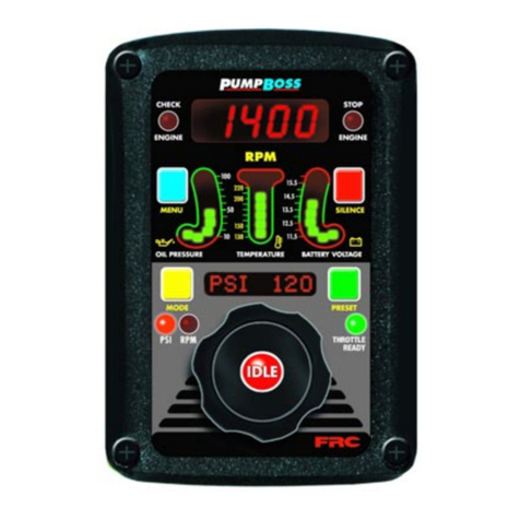
FRC PumpBoss PBA100 User manual

PBA100 Rev0407
1
FIRE RESEARCH CORPORATION
www.fireresearch.com
26 Southern Blvd., Nesconset, NY11767
TEL ( 631 ) 724-8888 FAX ( 631 ) 360-9727 TOLL FREE 1-800-645-0074
PRESSURE GOVERNOR
with DISPLAY and MONITORING SYSTEM
MODEL: PBA100
Document Number:
XE-PBA1PM-R0A

PBA100 Rev0407
2
CONTENTS
Table of Contents
CONTENTS ................................................................................................................ 2
INTRODUCTION ...................................................................................................... 4
Overview ................................................................................................................ 4
Features .................................................................................................................. 4
Specifications ......................................................................................................... 5
GENERAL DESCRIPTION ....................................................................................... 6
Controls and Indicators .......................................................................................... 8
INSTALLATION ...................................................................................................... 10
Install Control Module ......................................................................................... 10
Install Pressure Sensor ......................................................................................... 12
Install Engine Sensors .......................................................................................... 13
Install Buzzer ....................................................................................................... 13
Install High Idle Kit ............................................................................................. 13
OPERATION ............................................................................................................ 14
Controls ................................................................................................................ 14
Pressure Mode Operation .................................................................................... 16
RPM Mode Operation .......................................................................................... 18
Switching Between Operating Modes ................................................................. 19
Pump Discharge Pressure is High at Engine Idle ................................................ 19
Preset Settings (Pressure or RPM) ....................................................................... 20
High Idle .............................................................................................................. 20
Display Stored Data ............................................................................................. 21
PROGRAMMING .................................................................................................... 22
Program Code Descriptions ................................................................................. 23
WIRING .................................................................................................................... 24
Connectors and Cables ........................................................................................ 24
Pressure Sensor .................................................................................................... 26
Common OEM Diagnostic Connector ................................................................. 27
Cummins Harness Connections ........................................................................... 28
Detroit Diesel Harness Connections .................................................................... 29
Navistar Harness Connections ............................................................................. 30
Caterpillar Harness Connections ......................................................................... 31
Ford Harness Connections ................................................................................... 32
Ford Torque Lock-up Module .............................................................................. 33
Scania Harness Connections ................................................................................ 34
GMC Harness Connections ................................................................................. 35
Mercedes Harness Connections ........................................................................... 36
High Idle Wiring .................................................................................................. 37
FLYBACK DIODE INFORMATION ...................................................................... 38

PBA100 Rev0407
3
List of Tables
Table 1. Pressure Sensor Output Voltage .................................................................. 5
Table 2. Error Codes ................................................................................................ 15
Table 3. Fault Warning Codes .................................................................................. 15
List of Figures
Figure 1. Controls and Indicators ............................................................................... 9
Figure 2. Control Module Mounting Dimensions.................................................... 11
Figure 3. Pressure Sensor Dimensions ..................................................................... 12
Figure 4. PBA 12-Pin Connector Wiring ................................................................. 24
Figure 5. PBA 8-Pin Connector Wiring ................................................................... 25
Figure 6. Pressure Sensor Wiring ............................................................................. 26
Figure 7. Common OEM 9-Pin Diagnostic Connector ............................................ 27
Figure 8. Cummins PBA101 Wiring ........................................................................ 28
Figure 9. Detroit Diesel PBA102 Wiring ................................................................. 29
Figure 10. Navistar PBA104 Wiring ......................................................................... 30
Figure 11. Caterpillar PBA105 Wiring ..................................................................... 31
Figure 12. Ford PBA106-B Wiring ........................................................................... 32
Figure 13. Ford Torque Lock-up Module Wiring ..................................................... 33
Figure 14. Scania PBA108-B Wiring ........................................................................ 34
Figure 15. GMC PBA109 Wiring ............................................................................. 35
Figure 16. Mercedes PBA110 Wiring ....................................................................... 36
Figure 17. High Idle Wiring ...................................................................................... 37
Figure 18. Flyback Diode ........................................................................................ 38

PBA100 Rev0407
4
INTRODUCTION
Overview
The Fire Research PumpBoss pressure governor uses state of the art programmable
microprocessor technology and operates in one of two modes, pressure or RPM. It will
maintain a steady pump discharge pressure within system capabilities by controlling
the engine speed. When selected, it will also maintain a selected engine RPM.
In pressure mode the PumpBoss maintains a constant pump discharge pressure.
The discharge pressure is monitored and compared to the selected pressure setting, the
engine RPM is varied to keep the discharge pressure at the selected setting.
In RPM mode the PumpBoss maintains a constant engine RPM. The pump
discharge pressure is monitored, it can vary but will be limited to an increase of 30 PSI.
If the discharge pressure increases 30 PSI, the pressure governor will automatically
lower the engine RPM to reduce the discharge pressure.
All controls and indicators are located on the front of the control module.
Features
J1939 CAN Bus for Engine Information and Control
Power Up in Pressure Mode
Automatic Regulation of Pump Discharge Pressure
Manual Control of Pressure or Engine RPM Settings
Programmable Presets
Diagnostic Capabilities
No Pressure or RPM Variation When Changing Modes
Limits Increase of Pressure When in RPM Mode
Recognition of No Water Condition With Automatic Response
Interlock Signal Recognition with Throttle Ready LED
Return to Engine Idle With the Push of a Button
High Idle
Audible Alarm Buzzer (Optional)
Transmission Temperature Sensor (Optional)
KPa (Optional)

PBA100 Rev0407
5
Specifications
The PumpBoss is available in various models. Each model is programmed to
interface with specific engines. All models provide the same functions, controls, and
digital readouts for the management of pump discharge pressure.
Display Module
Supply Power: 12/24 VDC
Supply Current: 0.5 Amps
Dimensions: 4 5/8” Wide by 6 3/4” High
LED Bar Graphs
Oil Pressure: 10 - 100 PSI (10 PSI Increments)
Temperature (Engine Coolant): 130 - 240 °F (10° Increments)
Battery Voltage: 11.5 - 16 Volts (0.5 Volt Increments)
Engine Sensors
Engine Oil Pressure: 0 - 100 PSI, 1/8” NPTF
Engine Coolant Temperature: 100 - 250 °F, 1/2” - 14 NPT
Transmission Temperature: 140 - 320 °F, 1/8” NPTF
Pressure Sensor
Model Number: XE-PRO31PT2 XE-FP4000PT1
Pressure Range: 0 - 300 PSI 0 - 600 PSI
Proof Pressure: 800 PSI 1200 PSI
Excitation Voltage: 5 VDC 5 VDC
Output Voltage: 0.5 - 4.75 VDC (See Table 1)
Table 1. Pressure Sensor Output Voltage
0psi 100psi 150psi 200psi 250psi 300psi 600psi
XE-PRO31PT2 0.5vdc 1.917vdc 2.625vdc 3.33vdc 4.04vdc 4.75vdc N/A
XE-FP4000PT1 0.5vdc 1.12vdc 1.56vdc 1.92vdc 2.27vdc 2.625vdc 4.75vdc

PBA100 Rev0407
6
GENERAL DESCRIPTION
The PumpBoss pressure governors are compatible with the following engines:
PBA101 Cummins IS Series
PBA102 Detroit Diesel
PBA104 Navistar
PBA105 Caterpillar
PBA106* Ford
PBA108 Scania
PBA109* GMC
PBA110 Mercedes
* Note: An adapter and cable assembly replaces the basic 8-pin cable when
connecting the PumpBoss to a Ford or GMAC engine.
Components
The information available on the J1939 databus varies depending on the particular
engine type. Not all wires are used for all engines. Refer to the engine specific wiring
diagram for interface connections. The sensors (if any) that need to be installed will
also vary depending on the engine.
The PumpBoss consist of the following components:
Contol Module
Pressure Sensor
Engine Coolant Temperature Sensor (As Necessary)
Engine Oil Pressure Sensor (As Necessary)
Audible Alarm Buzzer (Optional)
Transmission Temperature Sensor (Optional)
Cables
Contol Module
The control module is waterproof and takes up 4 5/8 by 6 3/4 inches of panel
space. All controls and indicators are located on the front of the control panel. (Refer
to Controls and Indicators.)

PBA100 Rev0407
7
Pressure Sensor
The pressure sensor is mounted on the pump discharge manifold. It provides an
input signal to the control module that is proportional to the discharge pressure.
Engine Coolant Temperature Sensor
The engine coolant temperature sensor is installed as necessary.
Engine Oil Pressure Sensor
The oil pressure sensor is installed as necessary.
Audible Alarm Buzzer (Optional)
The optional buzzer is installed as required. A ground is provided at the 12-pin
connector pin 6 to activate the buzzer (max current: 300mA).
Transmission Temperature Sensor (Optional)
The optional transmission fluid temperature sensor is installed as required.
Cables
There are two cables that connect to the control module. The 8-pin connector is
for the remote throttle interface, the 12-pin connector is for the monitoring and display
interface.

PBA100 Rev0407
8
Controls and Indicators
All controls and indicators are located on the front of the control module. (Refer
to Figure 1.) See Operation and Programming Sections for more information.
OIL PRESSURE LED Display
Shows engine oil pressure. The LEDs will be green when the pressure is within
normal limits and red when it is not.
CHECK ENGINE LED
Repeats the check engine warning from the cab.
TEMPERATURE LED Display
Shows engine coolant temperature. The LEDs will be green when the temperature
is within normal limits and red when it is not.
RPM Display
Shows the current engine RPM in bright red digits. It also shows error codes, stored
data, and program features.
STOP ENGINE LED
Repeats the stop engine warning from the cab.
BATTERY VOLTAGE LED Display
Shows battery voltage. The LEDs will be green when the voltage is within normal
limits and red when it is not.
SILENCE Button
Press to suppress audio alarms.
PRESET Button
Press to change/select a pre-programmed value for pressure or RPM setting.
THROTTLE READY LED
This LED will be on when the required interlock conditions are met to begin pump
operations.
Message Display
The message display shows the pressure or RPM setting during normal operations
and warning alarms as they occur. It shows the time and date when the throttle ready
LED is off. It also shows stored data and program features.
IDLE Button
When pressed immediately sets the engine RPM to idle.

PBA100 Rev0407
9
Figure 1. Controls and Indicators
Control Knob
When rotated changes the pressure or RPM setting. The setting will increase or
decrease proportionally to the speed and direction the control knob is rotated.
RPM LED
The LED is on to indicate operation in the RPM mode.
PSI LED
The LED is on to indicate operation in the PSI mode.
MODE Button
Press to change modes.
Day/Night Sensor
Adjusts the brightness of the LED displays for best day or night viewing.
MENU Button
Used when accessing stored data and program features.
RPM
Display
Message
Display
OIL
PRESSURE
LED Display
TEMPERATURE
LED Display
SILENCE
Button
MENU
Button
BATTERY
VOLTAGE
LED Display
Control Knob IDLE
Button
THROTTLE
READY
LED
RPM
LED
PSI
LED
MODE
Button
PRESET
Button
STOP
ENGINE
LED
CHECK
ENGINE
LED
Day/Night
Sensor

PBA100 Rev0407
10
INSTALLATION
Install Control Module
1. Measure and mark mounting location for control module panel cutout and
mounting screw holes. Make sure there is clearance behind the panel for
the module and cables before cutting holes. Refer to Figure 2 for layout and
dimensions.
2. Cut out a 3 1/2 by 5 3/4 inch hole.
3. Drill four holes, clearance or tapped, for 10-32 mounting screws.
4. Place control module in position and secure with screws.
5. Connect cables at rear of the control module. (Refer to Wiring section.)

PBA100 Rev0407
11
Figure 2. Control Module Mounting Dimensions
1 3/4" 4 5/8"
6 3/4"
Mounting holes are
clearance or tapped
for 10-32 screws.
3 1/2"
5 3/4"
Panel
Cutout 5 3/4"
4"
Maximum
Radius
1/2"

PBA100 Rev0407
12
Install Pressure Sensor
The discharge pressure sensor is mounted on the discharge manifold of the pump.
If there is a check valve in the discharge side of the pump, mount the discharge sensor
before the check valve. T-fittings can be used to mount the pressure sensors.
Note: Install the pressure sensor upright so that the water in the end of the
sensor is able to drain back into the pipe.
1. Screw the sensor into a 1/4-18 NPT hole.
Caution: Do not use the main body that houses the electronics to tighten the
pressure sensor. Damage to the sensor may occur.
2. Tighten the sensor with a 3/4-inch wrench on the lower hex fitting.
3. Connect the pressure sensor cable from the control module to the pressure
sensor. (Refer to Wiring section.)
Figure 3. Pressure Sensor Dimensions
Caution: Do not use the main
body that houses the electronics
to tighten the sensor. Damage to
the sensor may occur.

PBA100 Rev0407
13
Install Engine Sensors
For most engines, the PumpBoss receives engine RPM, oil pressure, and coolant
temperature data over the J1939 databus. Some engines do not broadcast this data over
the databus and sensors may need to be installed.
Note: The PumpBoss may need a programming change for some sensor inputs
to be recognized. If the sensor was not ordered as part of the PumpBoss
kit you may need to contact FRC technical support for programming
information.
The sensors are wired to the 12-pin connector at the rear of the control module.
Refer to the Wiring section for pinout and wire color information.
An input is provided for an optional transmission temperature sensor.
Install Buzzer
Pin 6 on the 12-pin connector at the rear of the control module is provided to
connect an optional buzzer. Connect the ground side of the buzzer to pin 6. Maximum
current through pin 6 is 300 mA. The buzzer ordered from FRC requires a 1-1/8 inch
diameter mounting hole. (Refer to the Wiring section.)
Install High Idle Kit
The high idle is activated when + VDC is provided to pin 7 (High Idle Active
Input) of the 12-pin connector and pin 6 (Interlock Input) of the 8-pin connector. Refer
to High Idle Wiring.
Note: It is important that the connection to the Interlock Input from the High
Idle circuit be isolated from the apparatus interlock wiring with the two
diodes. The pump must NOT be engaged when using the high idle
function and the THROTTLE READY LED will be off.

PBA100 Rev0407
14
OPERATION
On power-up the PumpBoss will be in the pressure mode of operating. The RPM
display will show engine at idle RPM, the three LED bar graphs will be green indicating
readings within normal ranges, and the message display will alternate between showing
the date and time.
If a monitored function is not within normal parameters the display will flash, the
RPM display will show an error or fault warning code and a description will show in the
message display. (Refer to Table 2. Error Codes or Table 3. Fault Warning Codes.)
If one of the inputs displayed by the LED bar graphs is not within normal range
the LEDs will be red.
When all necessary throttle enables are active and the interlock circuit is complete
the THROTTLE READY LED will light and the remote throttle will be controlling
engine RPM. The engine RPM control signal will be set at idle regardless of the control
knob position.
Controls
Control Knob
The control knob is used to adjust PSI and RPM settings. The PumpBoss will
sense how fast and in what direction the control knob is rotated and send a signal to
the ECM to increase or decrease the engine RPM proportionally.
If the control knob is rotated quickly; the engine RPM will change quickly.
If the control knob is rotated slowly; the engine RPM will change slowly.
• Rotate the control knob clockwise to increase engine RPM.
• Rotate the control knob counterclockwise to decrease engine RPM.
• Press the red IDLE button to immediately return the engine to idle.
MODE Button
Switches between PSI and RPM modes.
MENU Button
Selectss the accumulated hours mode.
SILENCE Button
The silence button is used to suppress an optional audio alarm and exit the
accumulated hours mode.
PRESET Button
Selects a pre-programmed value for pressure or RPM setting.

PBA100 Rev0407
15
Table 2. Error Codes
Table 3. Fault Warning Codes
RPM
Display
Message
Display
Probable Cause
E01 NO DATA >Datalink cable not connected / connected to wrong port
>Broken wire / bad connector contact on datalink cable
E02 NO RESP >No responce to control signal
E03 NO RPM >Datalink cable not connected / connected to wrong port
>Engine not running / ignition key on
>Broken wire / bad connector contact on alternator cable
E04 N/A N/A
E05 NO PSR Pressure sensor not detected
E06 N/A N/A
E07 N/A N/A
E08 Trans >Sensor cable not connected
>Broken wire / bad connector contact on sensor cable
>Defective temperature sensor
E09 ENG OIL' >Sensor cable not connected
>Broken wire / bad connector contact on sensor cable
>Defective pressure sensor
E10 ENG T' >Sensor cable not connected
>Broken wire / bad connector contact on sensor cable
>Defective temperature sensor
RPM
Display
Message
Display
Description
F01 -N/A
F02 -N/A
F03 HI RPM High Engine RPM
F04 -N/A
F05 PRES LOW Pump Cavitation
F06 HI BATT High Battery Voltage
F07 LOW BATT Low Battery Voltage
F08 Trans 'T High Transmission Temperature
F09 LOW OIL Low Engine Oil Pressure
F10 ENG TEMP High Engine Coolant Temperature

PBA100 Rev0407
16
Pressure Mode Operation
In the pressure mode of operation the PSI LED will be on. The PumpBoss will
maintain a constant discharge pressure within system capabilities. It will adjust the
engine RPM automatically to compensate for variations in pressure.
Note: When changing from RPM mode to pressure mode the pressure setting
will be the pressure that the pump was operating at in RPM mode.
1. Press and hold PSI mode button for 3 seconds.
Result: PSI LED goes on.
2. Press PRESET and/or rotate control knob to select pressure setting.
Result: Message display shows PSI setting, engine RPM changes.
3. Press IDLE button after operations to bring engine to idle RPM.
Result: Message display shows date and time, engine at idle RPM.
Opening/Closing Discharge Valves
In pressure mode the PumpBoss will maintain the pressure setting regardless of
the number of discharge lines that are opened or closed providing there is a sufficient
water supply. As lines are opened the discharge pressure will start to drop and the
PumpBoss will raise the engine RPM to maintain the required pressure. As lines are
closed the discharge pressure will start to rise and the PumpBoss will lower the engine
RPM to maintain the required pressure.

PBA100 Rev0407
17
Running Away From Water, No or Low Supply Water
There are situations during pump operations when there may be no or low supply
water. This can be due to an empty water tank, a problem on the intake line, or when
switching the water supply source.
The PumpBoss constantly monitors the discharge pressure and compares it to the
engine RPM
If discharge pressure drops very quickly (from air coming into the pump) the
PumpBoss will limit the RPM increase to +300 and not allow the engine to exceed
1900 RPM. If the discharge pressure does not increase after 3 seconds the PumpBoss
will reduce the engine speed by 150 RPM and this RPM will be held as long as the
pressure stays above 45 PSI. (See below for pressure drop below 45 PSI.) If at any time
a sufficient water flow is reestablished, the PumpBoss will resume normal operation.
If the discharge pressure starts dropping in pressure mode the PumpBoss will
increase the engine RPM and attempt to maintain the selected pressure setting. If an
increase in RPM does not bring the pressure up, the PumpBoss will recognize this as a
running away from water condition and hold the engine at a steady RPM. (The engine
will not go to the maximum RPM, it will hold at the RPM it recognized the running
away from water condition.) When the discharge pressure comes back up the engine
RPM will be adjusted to maintain the selected pressuire setting.
If the discharge pressure drops below 45 PSI but stays above 15 PSI the
PumpBoss will go into a low water cycle. It will set the engine to 1100 RPM, if the
pressure does not rise above 45 PSI in 7 seconds the PumpBoss will set the engine
at idle RPM. The PumpBoss will repeat the low water cycle as long as the discharge
pressure is between 15 and 45 PSI. When the pressure rises above 45 PSI the PumpBoss
will resume normal operation.
If the discharge pressure drops below 15 PSI the engine will be set at idle RPM.
When the discharge pressure rises above 15 PSI the PumpBoss will resume the low
water cycle.

PBA100 Rev0407
18
RPM Mode Operation
In the RPM mode of operation the RPM LED will be on. The PumpBoss will
maintain a constant engine RPM.
The pump discharge pressure can vary but, as a safety feature, the PumpBoss limits
the increase in pressure to 30 PSI over the last established PSI value. As the discharge
pressure approaches this limit the PumpBoss will automatically lower the RPM to
prevent a high pressure surge. The RPM LED will blink as the PumpBoss sets a lower
RPM. This lower RPM will be the new operating RPM setting.
Note: When changing from pressure mode to RPM mode the RPM setting
will be the RPM that the pump was operating at in pressure mode.
1. Press and hold RPM mode button for 3 seconds.
Result: RPM LED goes on.
2. Press PRESETand/or rotate control knob to select RPM setting.
Result: Message display shows RPM setting, engine RPM changes.
3. Press IDLE button after operations to bring engine to idle RPM.
Result: Message display shows date and time, engine at idle RPM.

PBA100 Rev0407
19
Switching Between Operating Modes
• No variation in discharge pressure or RPM will occur when changing between
pressure and RPM modes.
• When changing to RPM mode, the RPM setting will be the RPM that the pump
was operating at in pressure mode.
• When changing to pressure mode the pressure setting will be the pressure that
the pump was operating at in RPM mode.
When the PumpBoss is in idle:
Press the mode button and the PumpBoss switches modes immediately.
When the PumpBoss RPM display shows a value (operating at some setting):
Press and hold the mode button for 3 seconds and the PumpBoss changes modes.
(This is to avoid an accidental change over if the buttons get bumped.)
Pump Discharge Pressure is High at Engine Idle
Once the governor has set the engine to idle, it can do no more to reduce discharge
pressures. To reduce discharge pressure the pump operator can gate incoming water,
reduce pressure at the intake relief valve, gate discharges, or disable the pump.

PBA100 Rev0407
20
Preset Settings (Pressure or RPM)
The preset button allows the operator to go to a pre-programmed pressure or
RPM setting during operations. The setting will be shown in the message display. This
procedure is to change the setting in the program.
Note: The engine must be running and the pump engaged interlock circuit
must be closed (the THROTTLE READY LED must be on).
1. Press IDLE button.
Result: Engine goes to idle RPM
2. Press PSI or RPM mode button to select the setting to be changed.
Result: LED indicator goes on for mode selected.
Note: The RPM display must show IdLE before changing the preset.
3. Press and hold PRESET button. (Continue to hold through step 4.)
Result: Message display flashes then shows PSEt.
4. Rotate control knob to change preset setting.
5. Release PRESET button.
Result: The new preset is programmed. RPM display shows IdLE.
High Idle
The PumpBoss programming includes a high idle function.
To activate the high idle set interlocks as called for by SOP (normally this would
include the transmission in neutral and the parking brake on ). Set the High Idle switch
to ON.
Note: The pump must NOT be engaged when using the high idle function
and the THROTTLE READY LED will be off.
Change High Idle Setting
Note: The high idle is set at about 1000 RPM at the factory. (This value will
vary depending on the specific engine.)
1. With the engine running, set the high idle switch to ON.
2. Press and hold PRESET button for 3 seconds.
Result: RPM display will flash and show the high idle setting.
3. Keep pressing the PRESET button and rotate control knob to desired RPM.
4. Release PRESET button to store the new high idle setting.
Other manuals for PumpBoss PBA100
1
This manual suits for next models
9
Table of contents
Other FRC Controllers manuals