FreeWave FGR2-PE User manual

2201 Cantu Court Suite 215 Sarasota, FL 34232 Page 1 of 23
(941) 378-4242 (800-237-3928 Fax (941) 378-2765
Stewartsigns.com
Programming & Installing the FreeWave Model FGR2-
PE for a Wireless RF MODEM Connection
NOTE: JM Stewart utilizes an industrial 900 MHz RF Transceivers from FreeWave
Technologies, model FGR2-PE.
The FreeWave Wireless Transceiver (Model FGR2-PE) will arrive pre-configured
and installed inside the sign. It is not necessary for you to program these
Transceivers. Please skip to page 18 for installation instructions.
Programming the Transceivers
Start with the Transceiver that will be installed in your Building
1. Plug the Transceiver Ethernet Port #1 into either your computer (using an Ethernet
crossover cable) or a switch/router using a RJ-45 Ethernet cable. Connect the power
adapter to the radio and a 110 volt outlet.
2. You will need to assign your computer a static IP address on the same subnet to
access the radio. You can use 192.168.111.90. See Figure #1.
Figure #1

2201 Cantu Court Suite 215 Sarasota, FL 34232 Page 2 of 23
(941) 378-4242 (800-237-3928 Fax (941) 378-2765
Stewartsigns.com
3.
The default IP address of the Transceiver from the factory is 192.168.111.100. Open
your web browser (Internet Explorer) and type 192.168.111.100 into the address bar
of your web browser. See figure #2.
Figure #2
4.
You will be prompted for a user name and password. The default username for the
Administrator login is ‘admin’, the password is ‘admin.’ See figure #3.
Figure #3
NOTE: The first Window that you will see is the Status Window. This Window will include all of
your device information. Nothing on this screen is user adjustable. See figure #4

2201 Cantu Court Suite 215 Sarasota, FL 34232 Page 3 of 23
(941) 378-4242 (800-237-3928 Fax (941) 378-2765
Stewartsigns.com
Figure #4 Status Window
IP Setup:
This Window will be used to setup the IP address, Subnet Mask, and Default Gateway of the radio.
Please check with your Network Administrator before changing these settings. This Window will
also display the MAC address of the radio.
1. Configuring the “IP Setup”. See figure #5.
a. Click on “IP Setup”. The IP Setup Window will be displayed. See figure #5.

2201 Cantu Court Suite 215 Sarasota, FL 34232 Page 4 of 23
(941) 378-4242 (800-237-3928 Fax (941) 378-2765
Stewartsigns.com
Figure #5 IP Setup Window (Building Unit)
b. Enter the IP Address as 192.168.1.50.
c. Enter the Subnet Mask as 255.255.255.0.
d. Enter the Default Gateway as 192.168.1.1.
e. Leave the “Web Page Port” unchanged at 80.
f. Record the IP Addresses for each Transceiver on a piece of paper and tape it to the
Transceiver for future reference.
g. Click on “Save/Apply” to save your settings.
2. Configuring the “Serial Setup 1”.
a. Click on “Serial Setup 1”. The Serial Setup window will be displayed. See figure#6.
b. Set Mode to “TCP Server”.
c. Set Port to “3001”.
d. Set Baud Rate to “115200”.
e. Set Modbus RTU to “Enable”.
f. Click on “Save/Apply” to save your settings.

2201 Cantu Court Suite 215 Sarasota, FL 34232 Page 5 of 23
(941) 378-4242 (800-237-3928 Fax (941) 378-2765
Stewartsigns.com
Figure #6 “Serial Setup 1” Window (Building Unit)
3. Configuring the “Serial Setup 2”.
1. Click on “Serial Setup 2”. The Serial Setup window will be displayed. See figure
#7.
2. Set Mode to “Disabled”.
3. Click on “Save/Apply” to save your settings.

2201 Cantu Court Suite 215 Sarasota, FL 34232 Page 6 of 23
(941) 378-4242 (800-237-3928 Fax (941) 378-2765
Stewartsigns.com
Figure #7 “Serial Setup 2” Window (Building Unit)
4. Configuring the “Radio Setup”. See figure #8.
a. Click on “Radio Setup”.
b. Set the “Network Type” to “Point-to-Point”.
c. Set the Modem Mode to “Gateway”.
d. Click on “Save/Apply” to save your settings.
e. Click on “Call Book” (near the bottom of the “Radio Setup” Window. This will
open the Call Book Window. See figure #9.
f. Call Book Window enter the serial number of the OTHER Transceiver in the
space provided in line 0. See figure #9. (The Serial Number of the Transceiver
can be found on the label attached to the Transceiver).
g. Click on “Save/Apply” to save your settings.
h. Click on “Radio Setup” to get back to the “Radio Setup Browser Window”
i. Click on “Save/Apply” and then “Reboot” button for the ALL the changes to
take effect.
j. Close all Browser Windows. This concludes the programming of the Transceiver
for your building.

2201 Cantu Court Suite 215 Sarasota, FL 34232 Page 7 of 23
(941) 378-4242 (800-237-3928 Fax (941) 378-2765
Stewartsigns.com
Figure #8 Radio Setup Window (Building Unit)
Figure #9 Call Book Window (Building Unit)

2201 Cantu Court Suite 215 Sarasota, FL 34232 Page 8 of 23
(941) 378-4242 (800-237-3928 Fax (941) 378-2765
Stewartsigns.com
Setting up the RF MODEM that will be installed in your Sign
1. Plug the Transceiver into either your computer (using an Ethernet crossover cable) or
a switch/router using a RJ-45 Ethernet cable. Connect the power adapter to the radio
and a 110 volt outlet.
2. You will need to assign your computer a static IP address on the same subnet to
access the radio. You can use 192.168.111.90. See Figure #10.
Figure #10
3. The default IP address of the Transceiver from the factory is 192.168.111.100. Open
your web browser (Internet Explorer) and type 192.168.111.100 into the address bar
of your web browser. See figure #11.
Figure #11
4. You will be prompted for a user name and password. The default username for the
Administrator login is ‘admin’, the password is ‘admin.’ See figure #12.

2201 Cantu Court Suite 215 Sarasota, FL 34232 Page 9 of 23
(941) 378-4242 (800-237-3928 Fax (941) 378-2765
Stewartsigns.com
Figure #12
NOTE: The first Window that you will see is the Status Window. This Window will include all of
your device information. Nothing on this screen is user adjustable. See figure #13
Figure #13 Status Window (Sign Unit)

2201 Cantu Court Suite 215 Sarasota, FL 34232 Page 10 of 23
(941) 378-4242 (800-237-3928 Fax (941) 378-2765
Stewartsigns.com
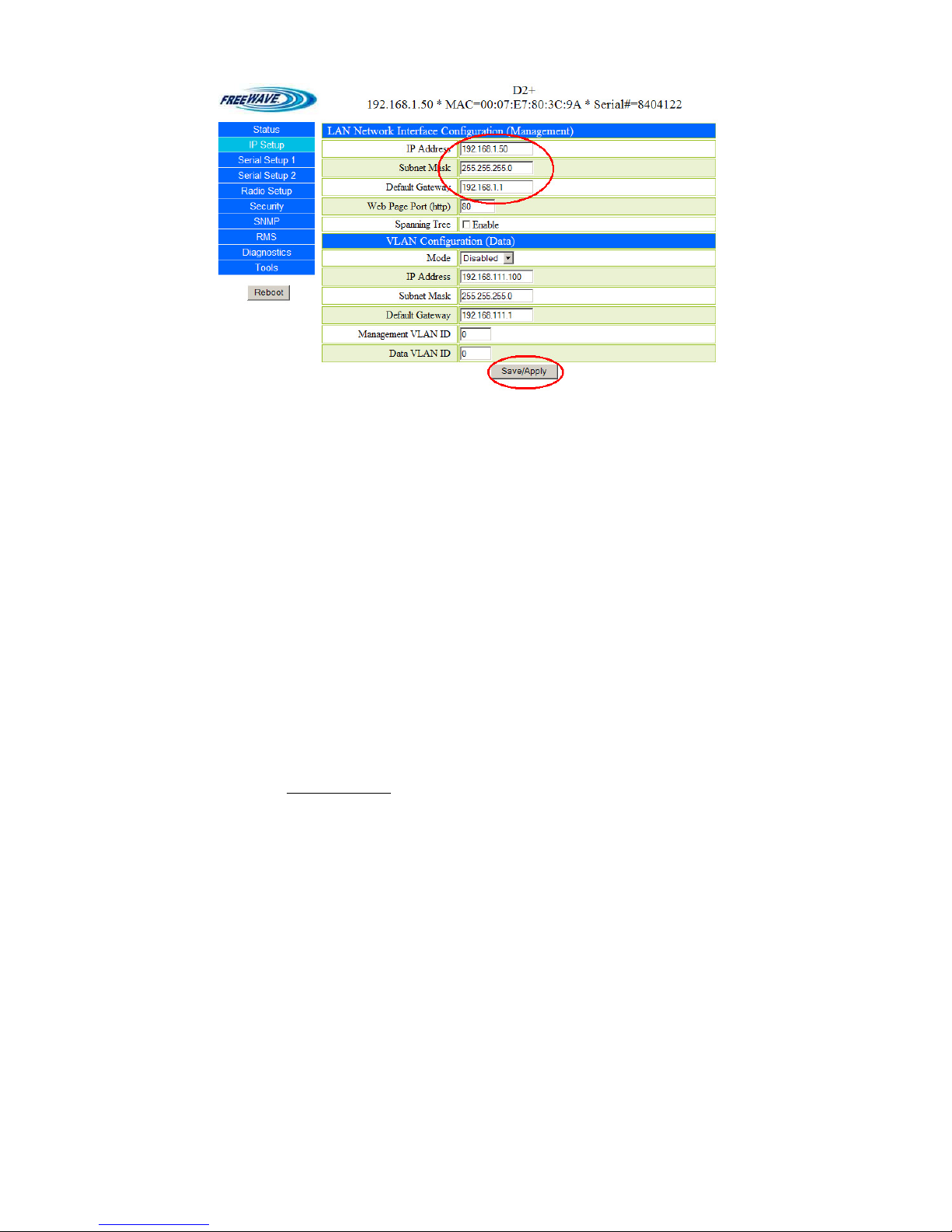
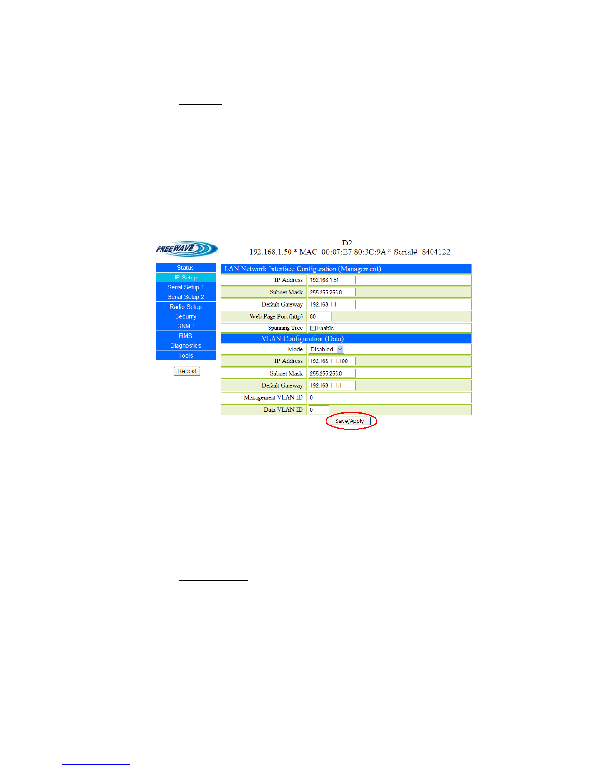
5. Configuring the “IP Setup” for the RF MODEM that will be installed in your Sign.
See figure #14.
a. Click on “IP Setup”. The IP Setup Window will be displayed. See figure #14.
b. Enter the IP Address as 192.168.1.51.
c. Enter the Subnet Mask as 255.255.255.0.
d. Enter the Default Gateway as 192.168.1.1.
e. Leave the “Web Page Port” unchanged at 80.
f. Click on “Save/Apply” to save your settings
g. Record the IP Addresses for each Transceiver on a piece of paper and tape it to the
Transceiver for future reference.
Figure #14 IP Setup Window (Sign Unit)
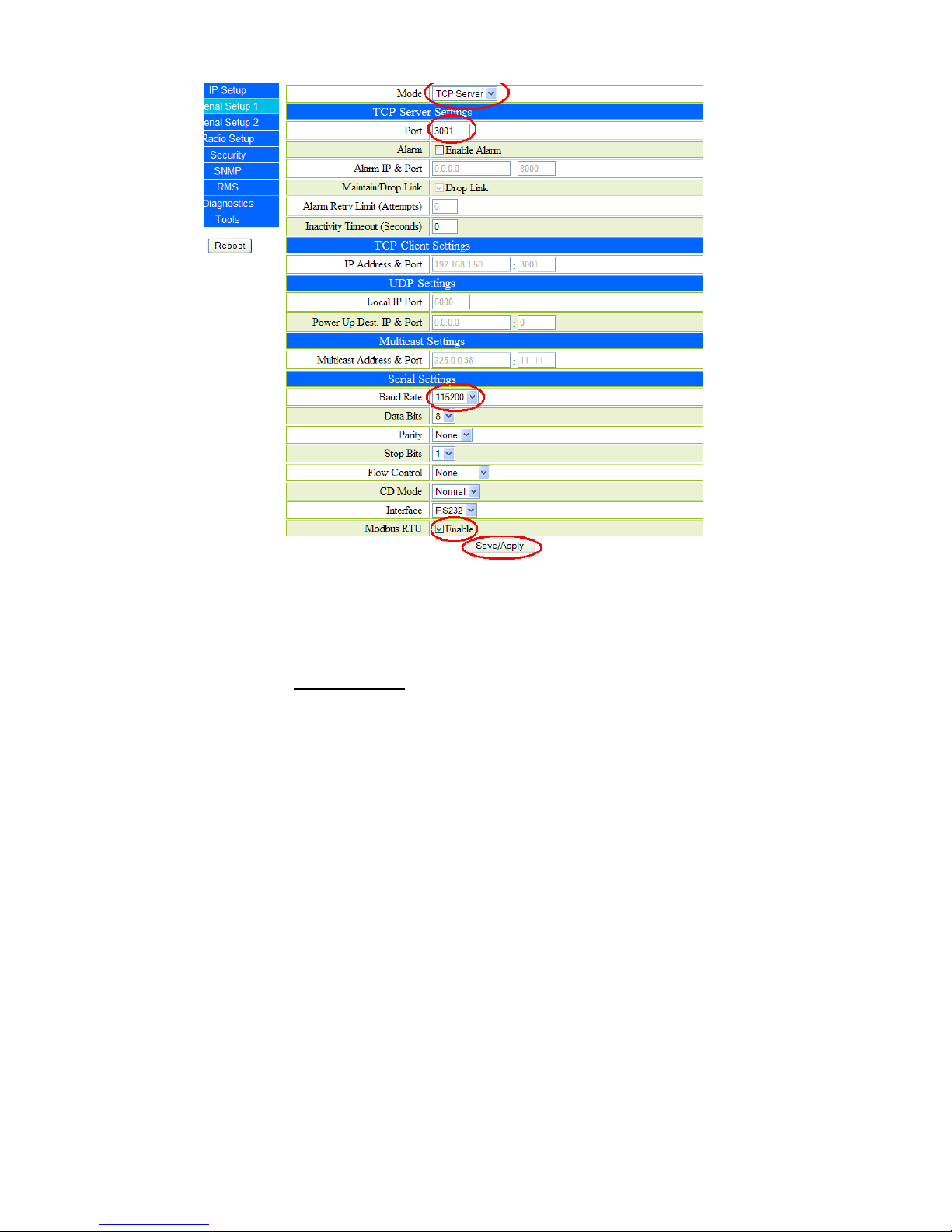
Configuring the “Serial Setup 1”. See figure #15.
1. Open your Web Browser and type the IP Address into in the address bar of this
Transceiver. (You programmed this in the previous step). See figure #2.
1. You will be prompted for a user name and password the default username for the
Administrator login is ‘admin’, the password is ‘admin.’ See figure #3.
2. Click on “Serial Setup 1”. The Serial Setup 1 window will be displayed.
3. Under “Mode” Select “TCP Server”
4. Enter “3001” in the box Labeled “Port”.
5. Change the “Baud Rate” to 115,200.
6. Click on “Modbus RTU” to Enable.
7. Click on “Save/Apply” to save your settings.

2201 Cantu Court Suite 215 Sarasota, FL 34232 Page 11 of 23
(941) 378-4242 (800-237-3928 Fax (941) 378-2765
Stewartsigns.com
Figure #15 “Serial Setup 1” Window (Sign Unit)
8. Configuring the “Serial Setup 2”. See figure #16.
1. Click on “Serial Setup 2”. The Serial Setup window will be displayed. See figure
#15.
2. Set Mode to “Disabled”.
3. Click on “Save/Apply” to save your settings.

2201 Cantu Court Suite 215 Sarasota, FL 34232 Page 12 of 23
(941) 378-4242 (800-237-3928 Fax (941) 378-2765
Stewartsigns.com
Figure #16 “Serial Setup 2” Window (Sign Unit)
9. Configuring the “Radio Setup”. See figure #17.
1. Click on “Radio Setup”.
2. Set the “Network Type to “Point-to Point”
3. Set the Modem Mode to “Endpoint”.
4. Click on “Save/Apply” to save your settings.
5. Click on “Call Book”. This will open the Call Book Window. See figure #18.
6. Call Book Window enter the serial number of the OTHER Transceiver in the space
provided in line 0. (The Serial Number of the Transceiver can be found on the label
attached to the Transceiver).
7. Click on “Save/Apply” to save your settings.
8. Click on “Radio Setup” to get back to the “Radio Setup Browser Window”
9. Click on “Save/Apply” to save your settings and then “Reboot” button for the
ALL the changes to take effect.
10. Close all Browser Windows. Your Transceiver is ready to install.

2201 Cantu Court Suite 215 Sarasota, FL 34232 Page 13 of 23
(941) 378-4242 (800-237-3928 Fax (941) 378-2765
Stewartsigns.com
Figure #17 Radio Setup Window
(Sign Unit)
Figure #18 Call Book Window
(Sign Unit)

2201 Cantu Court Suite 215 Sarasota, FL 34232 Page 14 of 23
(941) 378-4242 (800-237-3928 Fax (941) 378-2765
Stewartsigns.com
Installing the Transceivers
Included in the Transceiver box is the following:
a. 2 ea. RF Transceivers installed in a Metal Enclosure.
b. 1 set of Antenna adapters
c. 1 Antenna Extension cable (to be used inside the sign).
d. 1 Bulkhead Connector.
e. 2 ea. Antennas
f. 2 ea. power adapters
g. 1 ea. cable with RJ45 connector on one end and a 6 pin Panduit on the
other end.
h. 1 ea. 6 Ft. length Ethernet cable
i. Plastic Mounting Shoe.
Connecting your Transceiver to the CPU board in the Sign
1. One Transceiver will be installed inside ID cabinet #1 of the sign. ID cabinet #1 is
identified by the temperature probe mounted at the lower left corner of the LED
cabinet. Figure #19
Figure #19 The Temp Probe is Located at the Bottom Left of ID# 1
NOTE: To Avoid electrical shock be sure and Install the Transceiver in the Sign
BEFORE you plug in the Power Adapter.

2201 Cantu Court Suite 215 Sarasota, FL 34232 Page 15 of 23
(941) 378-4242 (800-237-3928 Fax (941) 378-2765
Stewartsigns.com
Figure #20 Transceiver inside the Sign.
Connect the RS232 Cable to “COM 1”
2. On ID cabinet ID#1, open the Lid on the LED portion of the sign by removing the
Phillips screws on the bezel surrounding the Lexan Lens.
3. Unscrew the Wing Nuts at the bottom of the LED panel and remove the bolts. Raise
the LED panel. Use the aluminum post located inside the sign to prop the LED
paned up. This will expose the electronics mounted to the inside rear of the LED
cabinet.
4. Attach the Antenna Cable to the Antenna Port on the Transceiver. Figure #20
5. Attach the Plastic Mounting Shoe. To the inside of the sign just below the electronic
circuit boards using sheet metal screws. Snap the transceiver into the Mounting
Shoe.
CAUTION: Do not place any electrical devices on the inside bottom of the LED
cabinet. Water can collect in this location before draining out of the
weep holes.
6. Connect the AC adapter provided to the AC receptacle inside the sign. It is highly
recommended to secure the AC adapter to the receptacle with a nylon zip tie.
Connect the other end to the power Receptacle on the Transceiver.

2201 Cantu Court Suite 215 Sarasota, FL 34232 Page 16 of 23
(941) 378-4242 (800-237-3928 Fax (941) 378-2765
Stewartsigns.com
7. Locate the serial cable. This cable has a RJ45 connector on one end and a Panduit
connector on the other end. Connect the RJ45 connector to the Serial Port on the
Transceiver identified as “COM 1”.
a. On Traditional CPU boards, attach the Panduit connector to the RS232
port CPU labeled “RS232” This CPU board is located inside ID cabinet
ID#1. See figure #21.
b. On New CPU boards connect the Panduit connector to RS232 port
board Marked “UART RS232”. This CPU board is located inside ID
cabinet ID#1. See figure #21a.
8. On Traditional CPU Boards only. Make sure the RS232 / RS485 jumper is set
correctly. Locate jumper pin set marked JP5, (This jumper is located 1 inch above
and to the right of the connector you plugged the cable into in the previous step).
The jumper should be on the set of pins marked 232. See figure #21.
9. Most New signs have the Antenna mount on the right side of the sign nine inches
below the top of the cabinet. Make sure all antenna connections are secure.
Figure #21 Traditional CPU Board inside the Sign

2201 Cantu Court Suite 215 Sarasota, FL 34232 Page 17 of 23
(941) 378-4242 (800-237-3928 Fax (941) 378-2765
Stewartsigns.com
Figure #21a New CPU Board inside the Sign
Mounting the External Antenna
1. Drill a 5/8” hole in ID#1 side of LED cabinet 9 inches below the top of the LED cabinet to
accommodate the bulkhead connector. Be careful not to interfere with the light Sensor
mounted inside the cabinet. See figure #22
2. Mount the bulkhead connector in the hole you drilled in step#1. The “O” ring goes on the
outside of the cabinet. The lock washer and retaining nut goes on the outside of the
cabinet. See figure #23.

2201 Cantu Court Suite 215 Sarasota, FL 34232 Page 18 of 23
(941) 378-4242 (800-237-3928 Fax (941) 378-2765
Stewartsigns.com
Figure #22 Mounting the External Antenna
Figure #23 Installing the Bulkhead Connector
3. For weather proof seal wrap external half of the bulkhead connector as well as 2 inches of
the base of the antenna in the Arlon Silicone Self-Fusing Electrical Tape. See figure #23
4. Inside the sign screw the 10 ft. antenna cable to the bulkhead connector.
5. Dress the antenna cable and screw the other end of the antenna cable to the transceiver.
Secure in place with nylon cable ties.

2201 Cantu Court Suite 215 Sarasota, FL 34232 Page 19 of 23
(941) 378-4242 (800-237-3928 Fax (941) 378-2765
Stewartsigns.com
Figure #23 Wrapping the Antenna in Silicone Self-Fusing Electrical Tape
Connecting your Transceiver to the PC in your Building
1. Locate the Serial cable included with Transceiver. Attach one end of this cable to
the #1 COM Port on the Transceiver. See figure #25.
2. Attach the other end of the Serial cable to the Rs232 Serial port on your P.C..
3. Connect the AC adapter provided to an AC receptacle. Connect the other end to the
“Power” receptacle on the Wireless Transceiver. See figure #25.
4. Using the included antenna adapters attach the antenna to the Antenna Port on the
Transceiver. See figure #25.
5. After both Transceivers are connected, you should be able to successfully connect
to the sign using Complay Software.

2201 Cantu Court Suite 215 Sarasota, FL 34232 Page 20 of 23
(941) 378-4242 (800-237-3928 Fax (941) 378-2765
Stewartsigns.com
Figure #25 The Transceiver Inside Your Building
Troubleshooting
Verifying Wireless Communications
When the Transceivers are in range of each other they will continuously “hand-shake” or
communicate with each other. This is indicated by a solid Green CD Light and a Flashing Red
CTS light. If you are not getting these lights on your transceiver they are most likely out of range
of each other. To correct this problem we recommend you move the Transceiver in your building
closer to the sign.
Other manuals for FGR2-PE
2
Table of contents
Other FreeWave Transceiver manuals

FreeWave
FreeWave Spread Spectrum User manual

FreeWave
FreeWave FGRO9CSU User manual

FreeWave
FreeWave LRS-455-EU User manual

FreeWave
FreeWave FGR09 Series User manual

FreeWave
FreeWave LRS400S User manual

FreeWave
FreeWave Spread Spectrum User manual

FreeWave
FreeWave MM2 User manual

FreeWave
FreeWave LRS455-C-U User manual

FreeWave
FreeWave FGR2 Use and care manual

FreeWave
FreeWave LRS455 SERIES User manual