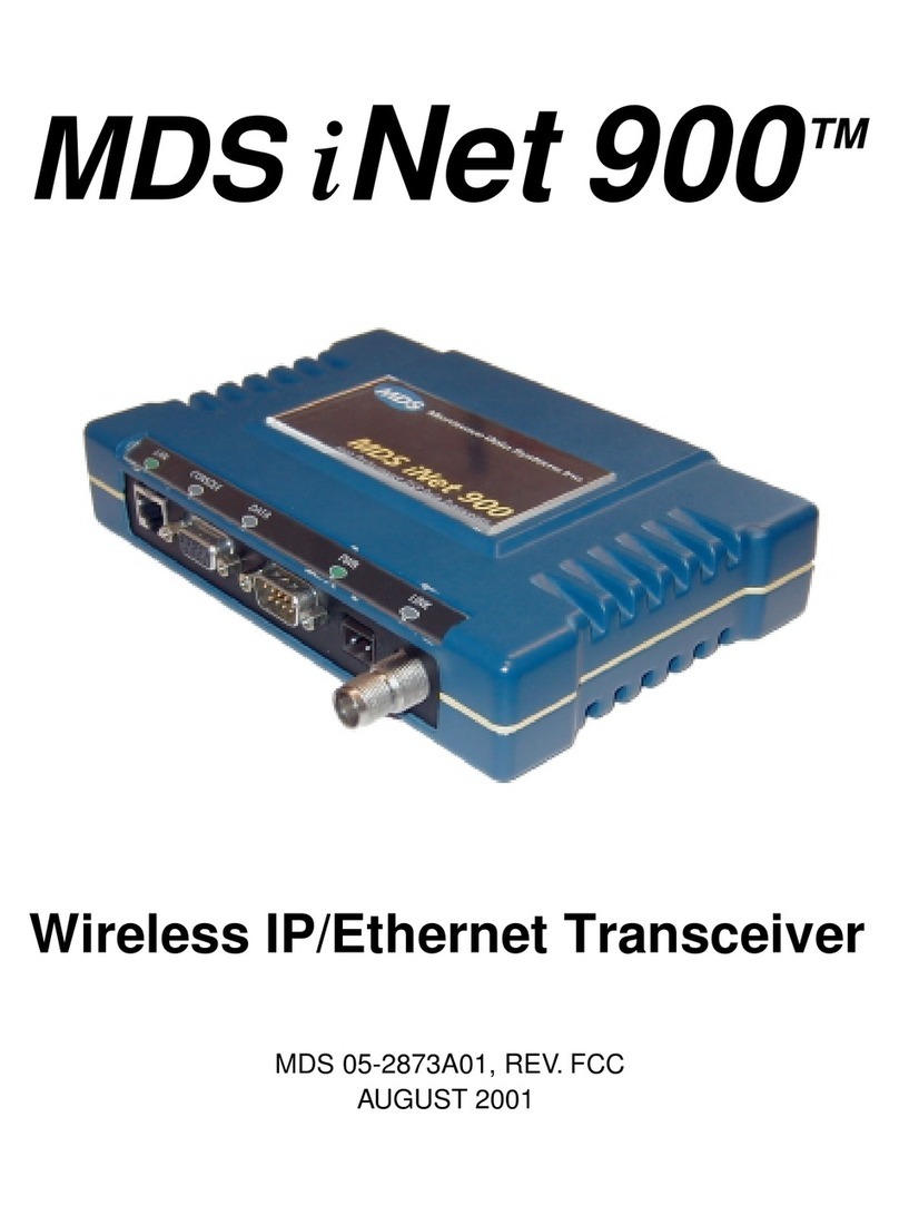
Microwave Data Systems MDS 4310 Owner's manual

About This Manual
175 Science Parkway, Rochester, N.Y. 14620, U.S.A.
Sales & Customer Support: +1 (716) 242-9600
FAX–All Services: +1 (716) 242-9620
World Wide Web: http://www.microwavedata.com/
NAVIGATING BY BOOKMARKS
A “bookmark” is the principal navigation tool in our PDF files. All of a file’s bookmarks are avail-
able when the “View Bookmarks and Page” is selected in your PDF viewer. Bookmarks in MDS’
PDF publications will usually list all primary and secondary headings found in the manual. In addi-
tion, there are bookmarks for the covers and other relevant information.
NAVIGATING BY THUMBNAILS
A second navigation tool is the “thumbnails” provided when “Thumbnails and Page” is selected in
your PDF viewer. This is suitable for casual scanning of the book as if you were thumbing through
the paper version. Clicking on the page thumbnail will take your view screen directly to that page.
You can also resize the view box on the thumbnail to change the magnification level and the area
being viewed.
NAVIGATING BY HOTLINKS
Many PDF versions of our manuals are equipped with hotlinks between portions of the docu-
ment. Links in the body are displayed as magenta colored strings of text. When your cursor
is positioned over a hotlink, the open hand will change into a pointing finger. Clicking on the
link location will move you to the associated section of the manual. In some manuals, the
hotlinksare onlyfound inthe Tableof Contents—onelink foreach majorsection. Theselinks
are indicated by magenta boxes with dashed lines.
PRINTING
This file contains all of the pages of the paper manual including the covers and is ready for printing.
The file will image each page exactly as it appears in the paper version if you have a 1200 dpi
printer. Lower resolution printers are supported, but highly detailed illustrations such as sche-
matics may not be as readable.
Some manuals will have 11 x 17 inch foldout pages. These pages will print on the default size of
8-1/2 x 11 inches in the “portrait” orientation scaled to fit on the page. To print the foldouts as they
appear in the paper manual, select 11 x 17 inch (“Tabloid”) paper stock and the “landscape” orien-
tation in the page set-up window and print the foldouts separately. (This assumes you have a large
format printer on-line.)
MDS ON THE INTERNET
For information on MDS products, technical support and publication updates, connect to our
Internet Web site at http://www.microwavedata.com/. Click on the address to launch your browser.

A CALIFORNIA MICROWAVE DIVISION
MDS 4310
350–512 MHZ
RADIO TRANSCEIVER
ANTENNA
INTERFACE
TD IN RD
TR MR CD
13.8 VDC
+–
Installation, Operation & Field Maintenance
Covering the MDS 4310 Transceiver with the 05-2314Axx PCB,
the MDS 4350 & 4355 Packaged Systems and All Basic Options
MDS 05-2415A01, Rev. A
SEPTEMBER 1994

MDS 2415A01, Rev. A Front Cover-B
MDS 4310 QUICK START GUIDE
Below are the basic steps for installing the MDS 4310 (350—512 MHz) Data Transceiver. The infor-
mation in parentheses indicates the chapters in this manual where detailed explanations are found.
1. Verify radio set-up parameters. (Chapters 2 & 3)
Check the test data sheets packed with the transceiver to be sure the radio is properly configured
for the intended application. Check especially for these items:
• Proper configuration of software selectable settings such as, CTS delay, soft carrier dekey
(SCD), squelch tail eliminator (STE), time-out timer (TOT) and PTT delay. Chapter 3 gives
instructions for setting these parameters.
• Transmit and Receive frequencies.
(Should be the same as those listed on the station license.)
• Transmitter RF power output.
• Loopback Code.
(Default loopback code consists of the last four digits of the radio’s serial number.)
• Transmit modulation and audio input characteristics.
• Modem speed (if radio is modem-equipped).
2. Securely mount the transceiver. (Chapter 2)
• Use the MDS supplied mounting brackets and four screws or bolts (fasteners not provided).
• Choose a mounting location that allows easy access to the connectors on the end of the radio
and allows an unobstructed view of the LED status indicators.
3. Install and connect the antenna system to the radio. (Chapter 2)
• Use good quality, low loss coaxial cable.
• Keep the antenna feedline as short as possible.
• Avoid sharp bends in the coaxial cable.
• Preset the antenna in the direction of the master station.
• Properly waterproof the antenna connector.
4. Connect and apply DC power to the radio. (Chapter 2)
• Set supply voltage to a nominal 13.8 volts.
• Observe polarity.
• Power cord must be properly fused (3 Amperes).
• Plug in the power plug and tighten the retaining screw.
5. Verify radio communications by observing the LED display. (Chapter 2)
• See Tables 2-2 and 2-3 for interpretation of status LEDs.
• Refine the antenna heading by using a DC voltmeter or Hand-Held Terminal (HHT) to measure
the radio’s received signal (RSSI).
6. Connect the data equipment to the radio INTERFACE connector. (Chapter 2)
• Connection must be made with a DB-25 Male (25 pin) connector.
• Connect only the required pins. Do not use a straight-through RS-232 cable with all pins wired.
• Verify the equipment connected to the INTERFACE connector is configured as DTE. The radio
is configured as DCE (data communications equipment).
• Pin connections for the INTERFACE connector are summarized in Table 2-1.

MDS P/N 05-2515A01, Rev. A
SEPTEMBER 1994
MDS 4310
350–512 MHz RADIO TRANSCEIVER
Including the…
MDS 4350 and MDS 4355 PACKAGE MODEL RADIOS
INSTALLATION, OPERATION
AND
FIELD MAINTENANCE
Copyright © 1994
Microwave Data Systems
All Rights Reserved
MICROWAVE DATA SYSTEMS
175 Science Parkway, Rochester, New York 14620
Telephone No.: 716-242-9600, FAX No.: 716-242-9620

The following are trademarks…
Thruline™—Bird, Inc.
HELIAX™—Andrew Corporation.
PCTALK™—The Headlands Press, Inc.
PCPLUS™—DataStorm Technologies, Inc.
PROCOMM™—DataStorm Technologies, Inc.
If further assistance with this product is required, please contact:
MICROWAVE DATA SYSTEMS
A Division of California Microwave Incorporated
175 Science Parkway
Rochester, New York 14620
Telephone No.: 716-242-9600
FAX No.: 716-242-9620
Copyright © 1994 by Microwave Data Systems
All rights reserved.

MDS 2141A01, Rev. A i
TABLE OF CONTENTS
CHAPTER 1—GENERAL
INTRODUCTION ------------------------------------------------------------------------------------------------------1-1
APPLICATIONS--------------------------------------------------------------------------------------------------------1-1
TERMS “ANALOG” AND “DIGITAL” ----------------------------------------------------------------------------1-2
MDS 4310 MODULATION TECHNIQUES -----------------------------------------------------------------------1-2
MICROCONTROLLER FEATURES -------------------------------------------------------------------------------1-2
SOFT CARIER DEKEY -----------------------------------------------------------------------------------------------1-3
CONTROL INPUTS AND OUTPUTS ------------------------------------------------------------------------------1-3
MODEL NUMBER CODES --------------------------------------------------------------------------1-4
MAIN PRINTED CIRCUIT BOARD MODELS --------------------------------------------------1-4
SPECIFICATIONS -----------------------------------------------------------------------------------------------------1-5
OPTIONAL EQUIPMENT, ACCESSORIES and CERTIFICATIONS -------------------------------------- 1-10
Special Certifications--------------------------------------------------------------------------------- 1-10
1200 BPS Bell 202T Modem------------------------------------------------------------------------ 1-11
4800 BPS Modem------------------------------------------------------------------------------------- 1-11
9600 BPS Modem------------------------------------------------------------------------------------- 1-11
Audio Processing Module---------------------------------------------------------------------------- 1-11
Order Wire Module----------------------------------------------------------------------------------- 1-11
Remote Maintenance Module (Internal)—P/N 03-1958A01 ----------------------------------- 1-11
Hand-Held Terminal---------------------------------------------------------------------------------- 1-12
RS-232 to RS-422 Converter Assembly—P/N 01-2358A01------------------------------------ 1-12
TTL to RS-232 Converter Assembly--------------------------------------------------------------- 1-12
CHAPTER 2—INSTALLATION
OVERVIEW -------------------------------------------------------------------------------------------------------------2-1
SURFACE MOUNTING ----------------------------------------------------------------------------------------------2-2
EXTERNAL CONNECTIONS ---------------------------------------------------------------------------------------2-4
ANTENNA Connector ---------------------------------------------------------------------------------2-4
DC IN (Power) Connector -----------------------------------------------------------------------------2-4
INTERFACE Connector -------------------------------------------------------------------------------2-4
INTERFACE Connector Pin Functional Descriptions---------------------------------------------2-7
FRONT PANEL INDICATORS------------------------------------------------------------------------------------ 2-11
TRANSCEIVER CONFIGURATION JUMPERS --------------------------------------------------------------- 2-12
J14—Receiver Audio Output Phase ---------------------------------------------------------------- 2-13
J16—Full Duplex Option Connector--------------------------------------------------------------- 2-13
MODEMS—GENERAL--------------------------------------------------------------------------------------------- 2-13
Introduction-------------------------------------------------------------------------------------------- 2-13
The Role of the Modem ------------------------------------------------------------------------------ 2-14
RTS and CTS Signals ------------------------------------------------------------------------------- 2-14
DCD Signal -------------------------------------------------------------------------------------------- 2-14
POWER REQUIREMENTS----------------------------------------------------------------------------------------- 2-14
ANTENNAS AND FEEDLINES----------------------------------------------------------------------------------- 2-15
Antenna Selection and Mounting ------------------------------------------------------------------- 2-15
Feedline Selection------------------------------------------------------------------------------------- 2-16
Feedline Installation ---------------------------------------------------------------------------------- 2-17

ii TABLE OF CONTENTS MDS 2141A01, Rev. A
CHAPTER 3—PROGRAMMING AND DIAGNOSTICS
INTRODUCTION------------------------------------------------------------------------------------------------------ 3-1
TERMINAL CONNECTION AND STARTUP ------------------------------------------------------------------- 3-1
Opening The Diagnostic Channel -------------------------------------------------------------------- 3-3
CAPABILITIES OF THE HHT -------------------------------------------------------------------------------------- 3-4
Review Operating Parameters and Diagnostic Information -------------------------------------- 3-4
Setting the Operating Parameters--------------------------------------------------------------------- 3-5
Program User Information ---------------------------------------------------------------------------- 3-5
USING THE HAND-HELD TERMINAL -------------------------------------------------------------------------- 3-5
Command Syntax--------------------------------------------------------------------------------------- 3-5
Shift Key------------------------------------------------------------------------------------------------- 3-5
Backspace (BKSP) Key ------------------------------------------------------------------------------- 3-5
Error Messages------------------------------------------------------------------------------------------ 3-6
Closing the Diagnostic Channel---------------------------------------------------------------------- 3-6
PROGRAMMING EXAMPLES------------------------------------------------------------------------------------- 3-6
PROGRAMMING OWNER’S INFORMATION ----------------------------------------------------------------- 3-8
PASSWORD PROTECTION----------------------------------------------------------------------------------------- 3-8
DIAGNOSTIC EVALUATION-------------------------------------------------------------------------------------- 3-8
Test Modes ---------------------------------------------------------------------------------------------- 3-9
EQUIPMENT DIAGNOSTICS DEFINITIONS------------------------------------------------------------------- 3-9
DIAGNOSTIC EXAMPLES-----------------------------------------------------------------------------------------3-10
RF Power Output Check -----------------------------------------------------------------------------3-10
Received Signal Strength Indication (RSSI) Check ----------------------------------------------3-10
PROGRAMMING AND TEST COMMANDS -------------------------------------------------------------------3-11
HAND-HELD TERMINAL SETUP DEFAULTS ---------------------------------------------------------------3-13
HAND-HELD TERMINAL WIRING -----------------------------------------------------------------------------3-14
Adapter Plug Wiring ----------------------------------------------------------------------------------3-14
HHT ALTERNATIVES ----------------------------------------------------------------------------------------------3-15
Cable Wiring for a PC or ASCII Terminal --------------------------------------------------------3-15
CHAPTER 4—FIELD TESTS AND ADJUSTMENTS
GENERAL -------------------------------------------------------------------------------------------------------------- 4-1
TEST EQUIPMENT REQUIRED ----------------------------------------------------------------------------------- 4-1
CONSTRUCTING A DATA TERMINAL EMULATOR-------------------------------------------------------- 4-3
REMOTE MAINTENANCE CONSIDERATIONS--------------------------------------------------------------- 4-5
INTRODUCTION TO FIELD TESTS & ADJUSTMENTS ----------------------------------------------------- 4-6
TEST PROCEDURES:
Basic Transceiver Checks ----------------------------------------------------------------------------- 4-7
Transmit Frequency, Squelch, Deviation and Receive Audio Output
For Radios with No Internal Modem-----------------------------------------------------4-10
For Radios with MDS’s Internal 1200 BPS Modem-----------------------------------4-11
For Radios with MDS’s Internal 4800 BPS Modem-----------------------------------4-14
For Units with MDS’s Internal 9600 BPS Modem ------------------------------------4-16
REMOTE MAINTENANCE MODULE—
Loopback Code Programming, Mode Selection, Calibration & Testing ----------------------4-19

MDS 2141A01, Rev. A TABLE OF CONTENTS iii
CHAPTER 5—THEORY OF OPERATION
RECEIVE FRONT END-----------------------------------------------------------------------------------------------5-1
HIGH IF ------------------------------------------------------------------------------------------------------------------5-1
LOW IF -------------------------------------------------------------------------------------------------------------------5-1
RECEIVE AUDIO ------------------------------------------------------------------------------------------------------5-1
SQUELCH ---------------------------------------------------------------------------------------------------------------5-2
POWER SUPPLY-------------------------------------------------------------------------------------------------------5-2
TRANSMIT POWER AMPLIFIER----------------------------------------------------------------------------------5-3
ANTENNA SWITCH --------------------------------------------------------------------------------------------------5-3
DIRECTIONAL COUPLER-------------------------------------------------------------------------------------------5-3
KEYLINE AND CONTROL CIRCUITS ---------------------------------------------------------------------------5-3
RADIO DISABLE ------------------------------------------------------------------------------------------------------5-3
AUDIO/DATA MODULATION INPUT SWITCHING----------------------------------------------------------5-4
MICROCONTROLLER/EEPROM ----------------------------------------------------------------------------------5-4
DIAGNOSTICS DATA CONTROL ---------------------------------------------------------------------------------5-4
TRANSMIT AUDIO ---------------------------------------------------------------------------------------------------5-5
PLL/SYNTHESIZER---------------------------------------------------------------------------------------------------5-5
RS-232 DATA INTERFACE------------------------------------------------------------------------------------------5-5
LED INDICATORS ----------------------------------------------------------------------------------------------------5-5
CHAPTER 6—TROUBLESHOOTING
This section contains basic field troubleshooting assistance for the transceiver system.
APPENDIX A—1200 BPS BELL 202T COMPATIBLE MODEM
INTRODUCTION -----------------------------------------------------------------------------------------------------A-1
SPECIFICATIONS ----------------------------------------------------------------------------------------------------A-1
ALIGNMENT ----------------------------------------------------------------------------------------------------------A-1
THEORY OF OPERATION------------------------------------------------------------------------------------------A-2
APPENDIX B—4800 BPS FSK MODEM
INTRODUCTION -----------------------------------------------------------------------------------------------------B-1
SPECIFICATIONS ---------------------------------------------------------------------------------------------------- B-1
INSTALLATION ------------------------------------------------------------------------------------------------------B-1
ALIGNMENT ---------------------------------------------------------------------------------------------------------- B-1
THEORY OF OPERATION------------------------------------------------------------------------------------------ B-1
APPENDIX C—9600 BPS FSK MODEM
INTRODUCTION -----------------------------------------------------------------------------------------------------C-1
SPECIFICATIONS ---------------------------------------------------------------------------------------------------- C-1
INSTALLATION ------------------------------------------------------------------------------------------------------C-1
ALIGNMENT ---------------------------------------------------------------------------------------------------------- C-1
THEORY OF OPERATION------------------------------------------------------------------------------------------ C-1

iv TABLE OF CONTENTS MDS 2141A01, Rev. A
APPENDIX D—REMOTE MAINTENANCE MODULE
INTRODUCTION----------------------------------------------------------------------------------------------------- D-1
OPERATION ---------------------------------------------------------------------------------------------------------- D-1
MODULE ADJUSTMENTS & CALIBRATION ---------------------------------------------------------------- D-2
DETERMINING THE PRESENCE OF A REMOTE MAINTENANCE MODULE ----------------------- D-2
INSTALLATION & REPLACEMENT---------------------------------------------------------------------------- D-3
TESTING THE LOOPBACK CODE ------------------------------------------------------------------------------ D-4
TROUBLESHOOTING ---------------------------------------------------------------------------------------------- D-4
THEORY OF OPERATION ----------------------------------------------------------------------------------------- D-5
APPENDIX E—ORDER WIRE MODULE
INTRODUCTION------------------------------------------------------------------------------------------------------E-1
THEORY OF OPERATION ------------------------------------------------------------------------------------------E-2
APPENDIX F—MDS 4355 REMOTE RADIO PACKAGED SYSTEM
GENERAL INFORMATION----------------------------------------------------------------------------------------- F-1
INTERFACE ASSEMBLIES-----------------------------------------------------------------------------------------F-2
Analog Interface Assembly—P/N 03-1105A21 ---------------------------------------------------F-2
RS-232/TTL Digital Interface Assembly—P/N 03-1467A21 ------------------------------------F-2
POWER CONNECTIONS -------------------------------------------------------------------------------------------- F-3
Primary Power—J3------------------------------------------------------------------------------------- F-3
Power for Accessories ---------------------------------------------------------------------------------F-3
Back-up Battery ---------------------------------------------------------------------------------------- F-3
ANALOG INTERFACE BOARD CONNECTIONS—P/N 03-1105A21, Rev. C----------------------------F-4
Audio and Keyline—J1--------------------------------------------------------------------------------F-4
Additional Interface Connections --------------------------------------------------------------------F-4
Audio Alignment ---------------------------------------------------------------------------------------F-5
DIGITAL RS-232/TTL INTERFACE BOARD CONNECTIONS, P/N 03-1467A21 --------------------- F-11
Summary----------------------------------------------------------------------------------------------- F-11
RS-232 Digital Interface Connections------------------------------------------------------------- F-12
TTL Digital Interface Connections ---------------------------------------------------------------- F-12
Additional Interface Connections ------------------------------------------------------------------ F-12
Order Wire Audio Alignment ---------------------------------------------------------------------- F-12
APPENDIX G—MDS 4355 REMOTE RADIO PACKAGED SYSTEM
GENERAL INFORMATION---------------------------------------------------------------------------------------- G-1
CUSTOMER MODIFICATION ------------------------------------------------------------------------------------ G-2
MOUNTING ----------------------------------------------------------------------------------------------------------- G-2
INTERFACE ASSEMBLIES—Summary ------------------------------------------------------------------------- G-5
Analog Interface/Utility Assembly—P/N 03-2110A01------------------------------------------ G-5
RS-232 Digital Interface and Utility Board—P/N 03-2115A01 -------------------------------- G-5
USING THE MDS HAND-HELD TERMINAL------------------------------------------------------------------ G-5
POWER CONNECTIONS ------------------------------------------------------------------------------------------- G-6
Primary Power—TB2--------------------------------------------------------------------------------- G-6
Power for Accessories -------------------------------------------------------------------------------- G-7
Back-up Battery --------------------------------------------------------------------------------------- G-7

MDS 2141A01, Rev. A TABLE OF CONTENTS v
ANALOG INTERFACE/UTILITY BOARD CONNECTIONS—P/N 03-2110A01-------------------------G-8
Audio and Keyline—TB1-----------------------------------------------------------------------------G-8
Additional Interface Connections--------------------------------------------------------------------G-8
Audio Alignment---------------------------------------------------------------------------------------G-9
Order Wire Audio Alignment ------------------------------------------------------------------------G-9
DIGITAL INTERFACE/UTILITY BOARD CONNECTIONS—P/N 03-2115A01— -------------------- G-13
Summary ---------------------------------------------------------------------------------------------- G-13
RS-232 Digital Interface Connections ------------------------------------------------------------ G-13
Additional Interface Connections------------------------------------------------------------------ G-14
Order Wire Audio Alignment ---------------------------------------------------------------------- G-14
APPENDIX H—MDS 4310-HL
DATA TRANSCEIVER FOR USE IN HAZARDOUS LOCATIONS
INTRODUCTION -----------------------------------------------------------------------------------------------------H-1
CONDITIONS OF APPROVAL ------------------------------------------------------------------------------------H-1
APPENDIX I—CANADIAN CERTIFICATION
RSS APPROVALS -----------------------------------------------------------------------------------------------------I-1
RESTRICTIONS--------------------------------------------------------------------------------------------------------I-1
APPENDIX J—AUDIO PROCESSING MODULE
INTRODUCTION ------------------------------------------------------------------------------------------------------J-1
SPECIFICATIONS -----------------------------------------------------------------------------------------------------J-1
ALIGNMENT -----------------------------------------------------------------------------------------------------------J-2
CONFIGURATION ----------------------------------------------------------------------------------------------------J-2
TABLES
Table 2-1. DB-25 Interface Connector Pin Functions--------------------------------------------------------------2-6
Table 2-2. External Indicators For Radios Without Internal Modems ----------------------------------------- 2-11
Table 2-3. External Indicators For Radios WithInternal Modems----------------------------------------------2-12
Table 2-4. J11–External Interface TTL/RS-232 ------------------------------------------------------------------ 2-13
Table 2-5. J14 Receiver Audio Output Normal/Inverted -------------------------------------------------------- 2-13
Table 2-6. Signal Loss versus Cable Length and Type ---------------------------------------------------------- 2-16
Table 3-1. Diagnostic and Control Capabilities------------------------------------------------------------------- 3-10
Table 3-2. Programming and Test Commands-------------------------------------------------------------------- 3-11
Table 3-3. Hand-Held Terminal Operating Defaults -------------------------------------------------------------3-14
Table 4-1. Main Circuit Board Potentiometer Settings for Remote Maintenance------------------------------4-6
Table 4-2. Test Procedure Reference Chart -------------------------------------------------------------------------4-6
Table B-1. Settings for the MDS 4800 bps Modem’s Configuration Switch S1 ------------------------------ B-3
Table C-1. Settings for the MDS 9600 bps Modem’s Configuration Switch S1 ------------------------------ C-2
Table F-1. Interface Board J1 Connectors -------------------------------------------------------------------------F-11
Table G-1. Interface Board TB1 Connectors -------------------------------------------------------------------- G-13
Table J-1. P/N 03–2301A01 Configuration Switch Settings ------------------------------------------------------J-2

vi TABLE OF CONTENTS MDS 2141A01, Rev. A
ILLUSTRATIONS
Figure 1-1. MDS 4310 Model Number Codes---------------------------------------------------------------------- 1-4
Figure 1-2. Printed Circuit Model Number Location -------------------------------------------------------------- 1-5
Figure 1-3. MDS 4310 Transceiver—Major Assemblies --------------------------------------------------------1-13
Figure 2-1. Mounting Dimensions—Front View------------------------------------------------------------------- 2-3
Figure 2-2. Mounting Dimensions—Bottom View ---------------------------------------------------------------- 2-3
Figure 2-3. External Connections------------------------------------------------------------------------------------- 2-5
Figure 2-4. Received Signal Strength Indicator Calibration Chart (Typical)----------------------------------2-10
Figure 2-5. Location of Configuration Jumpers -------------------------------------------------------------------2-12
Figure 2-6. Detail of Configuration Jumpers—J14 ---------------------------------------------------------------2-13
Figure 3-1. Hand-Held Terminal Connected to the MDS 4310 Transceiver ----------------------------------- 3-2
Figure 3-2. MDS 4355 Packaged Transceiver---------------------------------------------------------------------- 3-2
Figure 3-2. Hand-Held Terminal Keypad --------------------------------------------------------------------------- 3-6
Figure 3-3. HHT Initialization Display -----------------------------------------------------------------------------3-13
Figure 3-4. DB-25 Interface Adapter Wiring ----------------------------------------------------------------------3-14
Figure 3-5. DB-9 to DB-25 Interface Cable Wiring --------------------------------------------------------------3-15
Figure 3-6. DB-25 to DB-25 Interface Cable Wiring-------------------------------------------------------------3-15
Figure 4-1. Remote Data Terminal Emulator Wiring-------------------------------------------------------------- 4-4
Figure 4-2. Construction Options for Building a Data Terminal Emulator------------------------------------- 4-4
Figure 4-3. VCO Lock Voltage Test Point-------------------------------------------------------------------------- 4-9
Figure 4-4. 1200 bps AFSK Modem --------------------------------------------------------------------------------4-13
Figure 4-5. 4800 BPS FSK Modem---------------------------------------------------------------------------------4-15
Figure 4-6. 9600 BPS FSK Modem---------------------------------------------------------------------------------4-17
Figure 4-7. Remote Maintenance Module--------------------------------------------------------------------------4-19
Figure 4-8. Remote Maintenance Screen---------------------------------------------------------------------------4-23
Figure 4-9. MDS 4310 Transceiver PC Board Test Points and Adjustments ---------------------------------4-25
Figure 5-1. MDS 4310 Transceiver Block Diagram --------------------------------------------------------------- 5-7
Figure A-1. 1200 bps Modem PC Board --------------------------------------------------------------------------- A-1
Figure A-2. Bell 202T Compatible Modem Block Diagram----------------------------------------------------- A-3
Figure B-1. MDS 4800 bps Modem Block Diagram --------------------------------------------------------------B-2
Figure B-2. MDS 4800 bps Modem Assembly Diagram ---------------------------------------------------------B-3
Figure C-1. MDS 9600 bps Modem Block Diagram --------------------------------------------------------------C-3
Figure C-2. 9600 bps Modem Assembly Diagram-----------------------------------------------------------------C-3
Figure D-1. Remote Maintenance Module, P/N 03-1958A01--------------------------------------------------- D-2
Figure E-1. Order Wire Module --------------------------------------------------------------------------------------E-1
Figure E-2. Order Wire Board Component Layout ---------------------------------------------------------------- E-2
Figure E-3. Order Wire Block Diagram -----------------------------------------------------------------------------E-3
Figure F-1. MDS 4350 Interior View--------------------------------------------------------------------------------F-1
Figure F-2. MDS 4350 Features & Dimensions--------------------------------------------------------------------F-2
Figure F-3. 03-1105A21 Keying Options, Analog Interface Assembly-----------------------------------------F-6
Figure F-4. MDS 4350 Packaged System Wiring Diagram ------------------------------------------------------F-7

MDS 2141A01, Rev. A TABLE OF CONTENTS vii
Figure F-5. Analog Interface Assembly 03-1105A21------------------------------------------------------------- F-9
Figure F-6. MDS 4350 Packaged System Wiring Diagram
with 03-1467A21 RS-232/TTL Interface ----------------------------------------------------------F-13
Figure F-7. RS-232/TTL Interface Assembly 03-1467A21 ----------------------------------------------------F-15
Figure G-1. MDS 4355 Interior (AC Version) with Fiberglass Enclosure Removed-------------------------G-1
Figure G-2. MDS 4355 Dimensions, Feed-Through Couplings & Mounting Points -------------------------G-2
Figure G-3. Exploded View of DC Version of System -----------------------------------------------------------G-3
Figure G-4. Exploded View of AC Version of System -----------------------------------------------------------G-4
Figure G-5. Plugs for Primary Power TB2 and Interface TB1 Connectors ------------------------------------G-7
Figure G-6. Keying Options for the 03-2110A01 Analog Interface/Utility PC Board --------------------- G-10
Figure G-7. MDS 4355 Packaged System Wiring Diagram
with the 03-2110A01 Analog Interface/Utility Board ------------------------------------------ G-11
Figure G-8. Analog Interface Assembly 03-2110A01 ---------------------------------------------------------- G-12
Figure G-9. MDS 4355 Packaged System Wiring Diagram ith the
03-2115A01 RS-232 Digital Interface & Utility PCB ------------------------------------------ G-15
Figure G-10. RS-232 Digital Interface and Utility Board ------------------------------------------------------ G-16
Figure J-1. Audio Processing Module Installation Diagram ------------------------------------------------------J-1
Figure J-3. 03-2301A01 Audio Processing Module---------------------------------------------------------------- J-2

viii TABLE OF CONTENTS MDS 2141A01, Rev. A
About This Manual
This manual covers three models in the MDS 4300 Series of 450 MHz radio transceivers.
The MDS 4310 is the basic transceiver, and it is the main focus of this manual. The MDS
4350 and MDS 4355 are packaged weatherproof models, which include the MDS 4310 radio
plus a power supply, back-up battery and interface/utility board, all mounted in a NEMA 4
enclosure. Appendix F of this manual covers the main features of the MDS 4350 and
Appendix G covers the MDS 4355. All discussions relating only to the MDS 4350 and MDS
4355 Packaged models will be clearly marked.
The following is a brief summary of the contents in each chapter of the manual.
Chapter 1—General, provides a general introduction to the MDS 4310 Transceiver and its
standard and optional equipment. A specifications table provides a detailed summary of the
radio’s electrical and mechanical features.
Chapter 2—Installation, contains steps for installation, hookup and checkout of the MDS
4310 Transceiver. Recommendations are also provided for feedline and antenna selection,
connection to external equipment, jumper configuration settings and other requirements for
planning a successful radio installation.
Chapter 3—Programming and Diagnostics, gives procedures for connecting a Hand-Held
Terminal, or a standard ASCII Terminal to the radio for accessing and controlling the
transceiver’s operating parameters and performing diagnostic checks.
Chapter 4—Field Tests and Alignments, contains detailed procedures for testing and
adjusting the equipment to ensure maximum performance. The procedures here are not
required for normal installations, but can be performed as an aid in diagnosing a suspected
problem, or following replacement or repair of an assembly.
Chapter 5—Theory of Operation, provides an overview of the circuits comprising the
MDS 4310 Transceiver. The text is supported with an oversized block diagram at the end of
the chapter to aid in understanding the material.
Chapter 6—Troubleshooting System Problems, contains recommended evaluation
procedures for system troubles, and suggests possible solutions.

MDS 05-2415A01, Rev. A 1-1
CHAPTER 1—GENERAL
INTRODUCTION
The MDS 4310 Transceiver offers continuous duty, high-performance data communications
in the 390–470 MHz frequency band. The transceiver is fully synthesized and can be pro-
grammed to operate on 12.5 kHz and 25 kHz channels within this range.
The MDS 4310 Transceiver can be supplied with a MDS 2314Axx main PC board or a MDS
2013Axx main PC board. Although the two PC boards are similar, this manual covers
transceivers with the 2314Axx main PC board. Refer to the MDS 05-2141A01 manual for
specific information regarding transceivers equipped with the 2013Axx main PC board.
The Transceiver’s design is highlighted by a compact and rugged die-cast aluminum case
which houses the basic RF unit, and all diagnostic and modem options. The MDS 4350 and
MDS 4355 are alternate weatherproof models which include the MDS 4310 radio plus a
power supply, back-up battery and interface/utility board, all mounted in a NEMA 4X
enclosure. Appendix F of this manual covers the main features of the MDS 4350 and
Appendix G covers the MDS 4355 Package.
The contents of this manual center on the MDS 4310 Data Transceiver. All discussions
relating only to the MDS 4350 and MDS 4355 Packaged models are clearly marked.
+
–
MDS 2000 DATA TRAN SCEIVER
TRANSCEIVER
The MDS 4310 Data Transceiver The MDS 4350 Packaged Radio
(MDS 4355 Similar in appearance)
APPLICATIONS
The MDS 4310 Data Transceiver is a single channel, half-duplex, radio designed for use in
multiple address systems (MAS) such as those licensed under Part 90 of the Federal
Communications Commission rules, with an emission designation of F1D, F2D, or F3D,
depending on application and configuration.
Continued on next page.

1-2 GENERAL MDS 05-2415A01, Rev. A
As a component of point-to-multipoint data telemetry systems, the MDS 4310 Transceiver is
well suited for such applications as:
• Supervisory Control and Data
Acquisition (SCADA)
• Telemetry Systems
• Energy Distribution Automation
• Information Systems
• Oil Fields and Pipelines
• Alarm Monitoring
• Security
MDS 4000 Series radio systems offer the advantage of a frequency band which in many areas
is specially coordinated to provide protection from co-channel interference. Because these are
primarily data-only channels, voice users are not likely to interfere with data transmission
and reception.
TERMS “ANALOG” AND “DIGITAL”
In all MDS literature, the terms “analog” and “digital” are commonly used to describe the
modulation modes and other signal characteristics of various products. The following are
examples of how these terms are commonly used in this manual.
Analog Modem, Analog Radio, Analog Mode—
These terms relate to equipment or operating modes using linear frequency modulation
and detection techniques. The circuitry handles analog communication signals, such as
audio frequency shift keying (AFSK) or analog voice frequency signals through the
system. Generally, these products or modes operate in the 50 to 1200 bits per second
(bps) data range in non-voice applications. Modulation sources include an internal MDS
brand 1200 bps modem or external 4-wire audio sources such as AFSK modems.
Digital Modem, Digital Radio, Digital Mode—
These terms relate to equipment or operating modes using non-linear frequency shift
keying modulation and detection techniques. The signal may alternate between two or
three discrete frequencies (FSK) depending on equipment configuration. Generally, these
products or modes operate in the 4800 and 9600 bps range.
MDS 4310 MODULATION TECHNIQUES
The MDS 4310 Transceiver can be modulated by either audio frequency shift keying (AFSK)
or frequency shift keying (FSK) controlled directly by the digital output of the MDS internal
modems. Alternatively, an external modem can be used for controlling AFSK transmission.
The MDS 4310 is capable of interfacing with data equipment at standard rates between 50
and 4800 bits per second (bps) with an asynchronous interface to the local terminal unit. The
MDS 4310 provides a synchronous or asynchronous interface at data speeds of 1200, 4800
and 9600 bps with one of the optional FSK modems installed internally.
MICROCONTROLLER FEATURES
The MDS 4310 Transceiver features an internal microcontroller that allows user
programming and control of operating parameters and interrogation of diagnostic data.
Programming of radio settings and monitoring of operating parameters can be done with a
terminal unit connected through the transceiver’s DB-25 INTERFACE connector, eliminating
the need to remove the radio from its mounting position or open its top cover. The terminal
can be either an MDS-supplied Hand-Held Terminal (HHT), or an IBM PC (or compatible)
personal computer running MDS-supplied software, or other PC-based communications

MDS 05-2415A01, Rev. A GENERAL 1-3
software (such as PCPLUS™, PROCOMM™, PCTALK™, etc.). As a third alternative, any
terminal with an RS-232 serial port can also be used.
With one of these devices connected, the user can program the transmit and receive
frequencies, RTS/CTS delay time, PTT delay, soft carrier dekey, time-out-timer, loopback
code and the MDS-patented Squelch Tail Eliminator circuit. In addition, an internal message
field (up to 27 characters) can be entered to label each transceiver with its own identity.
Password security and several other functions are also programmable.
Diagnostic functions that can be measured through the diagnostic module include received
signal strength indication (RSSI), various critical voltage levels, internal temperature,
forward power, and antenna/feedline VSWR. When equipped with the remote maintenance
module and used in a system with an MDS 4100 Series Master Station, several of these
diagnostic measurements can be sent over-the-air back to the master station for display by the
associated PC diagnostic software.
The internal micro-controller also provides basic indication of operating parameters and
values. While not a substitute for calibrated test equipment, this is useful for quick field
evaluations.
SOFT CARIER DEKEY
This feature can be used to keep the transmitter keyed for a short period of time (typically up
to 5 ms) after the last data bit has been transmitted. This period of silence provides a clear
indication that the message has ended and helps ensure no errors are introduced into the data
stream as a result of the transmitter unkeying too soon. The soft carrier dekey feature can be
selected or modified by using the HHT.
CONTROL INPUTS AND OUTPUTS
Four control inputs and outputs are provided on the MDS 4310 Data Transceiver’s 25-pin
“D” INTERFACE connector. They are:
1. Receiver Squelch. This output goes low when the receiver is squelched, and is
pulled high when the receiver squelch is open. When the squelch is open, this pin
supplies +8 Vdc through a 1 kΩresistor.
2. Out-of-Lock Alarm. When this output is low (less than 0.5 Vdc), it indicates normal
operation. A logic high (greater than 4 Vdc) indicates a failure in the phase lock loop
signal source, or a transmitter time-out condition.
3. Received Signal Strength Indicator. This analog signal output supplies a received
signal strength indicator (RSSI) voltage on Pin 21 of the DB-25 connector. The RSSI
voltage is proportional to the strength of the signal present at the antenna connector,
and provides a useful indication of signal levels between –120 dBm and –60 dBm.
This can be especially helpful during installation to aid in aiming the station antenna
for maximum received signal strength.
4. Radio Disable. When this input on Pin 12 of the INTERFACE connector senses a
ground, it disables or “turns off” most circuits in the radio, including transmit,
receive, modem and diagnostic functions. This reduces power consumption, yet
preserves the radio’s ability to be brought quickly online. Total current drain in the
disabled state is less than 14 mA.
The annunciator or LED indicator panel on the transceiver’s face shows the radio’s basic
performance without removing the housing cover. For transceivers without a built-in modem,
front-panel indicators are provided for primary power on, receive carrier detect, out-of-lock

1-4 GENERAL MDS 05-2415A01, Rev. A
alarm, transmit keyline activity and transmit status. When used with the modem option, an
annunciator panel indicates the status of the RS-232 interface lines (TXD, RXD, DCD, RTS,
CTS). If desired, the LED display can be turned off by moving a jumper inside the radio.
This may be desirable in applications where power consumption must be kept to an absolute
minimum.
MODEL NUMBER CODES
The model number as found on the serial number label may be used to determine the general
hardware configuration of the radio as it was shipped from the factory. Figure 1-1 illustrates
the significance of the various characters in the radio’s serial number. The serial number
label is located on the end of the radio enclosure.
POWER SETTING
(1) 12VDC
INTERFACE
(0) 4-Wire Audio
(2) 1200 BPS
(A) 4800 BPS
(D) 9600 BPS
DIAGNOSTICS
(0) None
(4) Remote Maint.
SAFETY CERTIFICATION
(0) N/A
(F) Factory Mutual / UL
OPERATION
(R) Base/Remote
BANDWIDTH
(1) 12.5 KHz
SEPARATION
(5) 5–10 MHz/Simplex
REGULATORY CERTIFICATION
(0) N/A
(1) FCC (USA)
(2) DOC RSS-119
(3) DOC RSS-122 (Canada)
FREQUENCY RANGE
(A) 390–406 MHz*
(E) 450–470 MHz*
(F) 406–430 MHz*
(G) 350–370 MHz
(H) 370–390 MHz
(I) 390–410 MHz
* 2013 printed circuit board only
(J) 406–430 MHz
(K) 430–450 MHz
(L) 450–470 MHz
(M) 470–490 MHz
(N) 490–512 MHz
●
This information is subject to configuration and change. Contact MDS
to verify certification.
4310RN 15
● ●●●●
1
Figure 1-1. MDS 4310 Model Number Codes
MAIN PRINTED CIRCUIT BOARD PCB VARIATIONS
The MDS 4310 Transceiver may be equipped with a 2314Axx main PC board or a 2013Axx
main PC board. The significant difference is the frequency range. Although the two PC
boards are similar, this manual covers transceivers with the 2314Axx main PC board which
has a frequency range of 350 to 512 MHz. Refer to manual part number MDS 05-2141A01
for specific information regarding transceivers equipped with the 2013Axx main PC board
which has a frequency range of 390 to 470 MHz. See Figure 1-2 for the location of the main
PCB part number label.
The main PC board part number can be identified without removing the housing cover. Refer
to Figure 1-1 to determine the transceiver frequency range. The frequency ranges identified
with a G, H I, J, K, L, M or N are equipped with the 2314Axx main PC board. The main PC
board part number can also be determined by using the HREV command via the HHT or
terminal. The HREV command displays the main PC board part number and the revision level.
The nominal frequency operating range of the transceiver PCB can also be determined by
using the MOD command via the HHT or terminal. The MOD command displays the main PC
board model number and the revision level.
See Chapter 3 –Programming and Diagnostics for detailed information on the use of the
Hand-Held Terminal.

MDS 05-2415A01, Rev. A GENERAL 1-5
3
4
1
2
34
12
1
2
3
PRINTED CIRCUIT
BOARD MODEL
LABEL
Figure 1-2. Printed Circuit Model Number Location
SPECIFICATIONS: MDS 4310 DATA TRANSCEIVER (2314 MAIN PC BOARD)
General
Frequency Range: 350–512 MHz (Nominal)
Operating Bands— 350–370 MHz, 370–390 MHz, 390–410 MHz,
any one of eight: 406–430 MHz, 430–450 MHz, 450–470 MHz,
470–490 MHz, and 490–512 MHz
Frequency Programming: Programmable in 6.25 kHz increments to any
channel pair in radio operating sub-band.
TX/RX Spacing: 0 (Simplex), 5 MHz, 10 MHz standard; others
are possible, consult with factory.
Primary Power—
Model 4310 Transceiver
Voltage: 13.8 Vdc Nominal
(10.5–16.5 Vdc Operating Range)
TX Supply Current: 2.0 A typical, 2.5 A Maximum, at 13.8 Vdc
Varies with power output adjustment
RX Supply Current: 65 mA typical, without options installed or
LED indicators turned OFF
Standby Current (Radio Inhibited) : 14 mA maximum
Connector: Integral part of power cable assembly
(Six foot/1.8 meter cable assembly included)
Fuse: 3.0 A, 3AG, FB (Fast Blow);
Holder part of cable assembly
Reverse Polarity Protection: Diode across primary power input with
internal 4 A plug-in fail-safe fuse.
Continued on next page.

1-6 GENERAL MDS 05-2415A01, Rev. A
General Continued
Model 4350 and 4355 Packaged Radios
Voltage: 120/220 Vac with 5 ampere-hour
Battery Back-up (Standard)
12, 24, 48, & 125 Vdc (Optional)
DC Supply: Positive, Negative;
Floating Ground with 24, 48, & 125 Vdc
TX Power Consumption: 50 watts maximum at rated output
RX Power Consumption: 5 watts maximum
Transient Protection: 2500 Volt Isolation on Voice Frequency (VF)
Inputs and Outputs, Power Supply & Keying
Dimensions:
Model 4310 Transceiver 2.0" x 5.62" x 7.25"
50 x 143 x 184 mm
(Not including mounting hardware or
connector housings)
Model 4350 Packaged Radio 9.5" x 17.5" x 19.5"
241 x 445 x 495 mm
(Not including mounting hardware or
connector housings)
Model 4355 Packaged Radio 6.5" x 11.85" x 13.75"
165 x 301 x 350 mm
(Not including mounting hardware or
connector housings)
Weight:
Model 4310 Transceiver Maximum 3.5 Lbs./1.6 kg
w/all options installed
Model 4350 Packaged Radio Maximum 33 Lbs/15.0 kg
w/all options installed
Model 4355 Packaged Radio Maximum 21 Lbs/9.53 kg
w/all options installed
Transmitter
Frequency Range: 350–512 MHz (Nominal)
Operating Bands— 350–370 MHz, 370–390 MHz, 390–410 MHz,
any one of eight: 406–430 MHz, 430–450 MHz, 450–470 MHz,
470–490 MHz, and 490–512 MHz
Frequency Programming: Programmable in 6.25 kHz increments to any
channel pair in radio operating sub-band.
TX/RX Spacing: 0 (Simplex), 5 MHz, 10 MHz standard; others
are possible, consult with factory.

MDS 05-2415A01, Rev. A GENERAL 1-7
Power Output: 5 Watts/+37 dBm (standard)
at the ANTENNA Connector
Adjustable down to 0.5 watt/+27 dBm
Duty Cycle: 100%/Continuous
Output Impedance: 50 Ohms
Forward & Reflected Power Detector: Built-in
Frequency Stability: ±0.00015% (1.5 PPM), –30°C to +60°C,
For All Models
RF Channel Bandwidth: 12.5 kHz (25 kHz Compatible)
Spurious & Harmonic Emissions: –65 dBc
TX Response Time: ≤4 ms
Modulation Type: FSK—With 4800 and 9600 bps modems
FM—With 1200 bps AFSK modem
Deviation: ±2.5 kHz Maximum
Time-Out Timer: Internal; Programmable from 1–255 Seconds,
or Off
Analog Model Audio Input
Characteristics—
Level: Adjustable, –20 to +10 dBm
for 2.5 kHz Deviation
Model 4310: 600 Ohms, Unbalanced
Model 4350: 600 Ohms, Balanced,
4-Wire Audio
Frequency Response: Model 4310: +1 dB, –3 dB, 50–3000 Hz
Model 4350: +1 dB, –3 dB, 300–3000 Hz
Soft Carrier Dekey: Programmable from 0 to 255 ms in 1 ms steps
Soft Carrier Dekey factory set to…
0 ms with no internal modem
0 ms with MDS 1200 baud modem
2 ms with 4800 FSK internal modem
4 ms with 9600 FSK internal modem
Transmitter Keying: Positive-going and negative-going,
TTL-compatible keying inputs are provided.
Inputs will operate with signal voltages
between 5 and 40 volts. Dry contact closures
are also suitable. Keyline input pins have an
input impedance of 10 kilohms and have built-
in over-voltage protection up to ±40 volts.
PTT Delay: Programmable from 0-31 ms in 1 ms steps
Table of contents
Other Microwave Data Systems Transceiver manuals

Microwave Data Systems
Microwave Data Systems MDS entraNET 900 Parts list manual

Microwave Data Systems
Microwave Data Systems MDS TransNET 900 Original operating instructions

Microwave Data Systems
Microwave Data Systems iNET 900 Series User manual

Microwave Data Systems
Microwave Data Systems MDS 2710D Original operating instructions

Microwave Data Systems
Microwave Data Systems MDS FIVE Series User manual

Microwave Data Systems
Microwave Data Systems iNET 900 Series User manual

Microwave Data Systems
Microwave Data Systems MDS 9810 Operating instructions