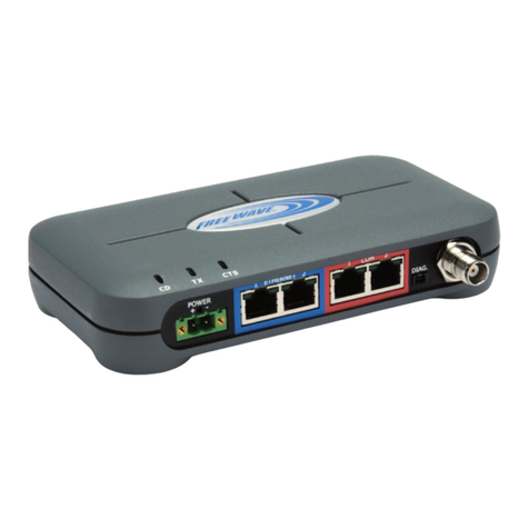
FreeWave Spread Spectrum User manual

FreeWave
Spread Spectrum
Wireless Data Transceiver
User Manual
FreeWave Technologies, Inc.
1880 South Flatiron Court
Boulder, CO 80301
USA
(303) 444-3862
(303) 786-9948
www.freewave.com


FreeWave
Spread Spectrum
Wireless Data Transceiver
User Manual
FreeWave Technologies, Inc.
1880 South Flatiron Court
Boulder, CO 80301
USA
(303) 444-3862
(303) 786-9948
www.freewave.com


FreeWave Technologies Spread Spectrum Transceiver User Manual
900 MHz and 2.4 GHz
V4.2f
i
This manual is for use by purchasers and other authorized users of the
FreeWave™ Wireless Data Transceiver only. No part of this document may
be reproduced or transmitted in any form or by any means, electronic or
mechanical, or for any purpose without the express written permission of
FreeWave Technologies, Inc.
Warranty
Your FreeWave Wireless Data Transceiver is warranted against defects in
materials and manufacturing for a period of two years from the date of
purchase. In the event of a product failure due to materials or workmanship,
FreeWave Technologies will, at its discretion, repair or replace the product.
FreeWave Technologies, its suppliers, and its licensors shall in no event be
liable for any damages arising from the use of or inability to use this product.
This includes business interruption, loss of business information, or other
loss which may arise from the use of this product.
Information in this document is subject to change without notice.
© 1995-2000 FreeWave Technologies, Inc. All rights reserved.
Microsoft and Windows are registered trademarks of the Microsoft Corporation.
pcANYWHERE is a registered trademark of Symantec Corporation.
Other product names mentioned in this manual may be copyrights, trademarks, or registered
trademarks of their respective companies and are hereby acknowledged.
The FreeWave Wireless Data Transceiver is made in the United States of America.
Printed in the United States of America.

FreeWave Technologies Spread Spectrum Transceiver User Manual
900 MHz and 2.4 GHz
V4.2f
ii

FreeWave Technologies Spread Spectrum Transceiver User Manual
900 MHz and 2.4 GHz
V4.2f
iii
FCC Notification
This device complies with part 15 of the FCC rules.
Operation is subject to the following two conditions: 1) This
device may not cause harmful interference and 2) this
device must accept any interference received, including
interference that may cause undesired operation.
This device must be operated as supplied by FreeWave
Technologies, Inc. Any changes or modifications made to
the device without the express written approval of
FreeWave Technologies may void the user's authority to
operate the device.
CAUTION: The model numbers DGR09 and DGR-115 have maximum
transmitted output power of 955mW and 1 Watt, respectively. It is
recommended that the transmit antenna be kept at least 23 cm away from
nearby persons to satisfy FCC RF exposure requirements.
Note: This equipment has been tested and found to comply with the limits
for a Class B digital device, pursuant to part 15 of the FCC Rules. These
limits are designed to provide reasonable protection against harmful
interference in a residential installation. This equipment generates, uses and
can radiate radio frequency energy and, if not installed and used in
accordance with the instructions, may cause harmful interference to radio
communications. However, there is no guarantee that interference will not
occur in a particular installation. If this equipment does cause harmful
interference to radio or television reception, which can be determined by
turning the equipment off and on, the user is encouraged to try to correct the
interference by one or more of the following measures:
♦Reorient or relocate the receiving antenna.
♦Increase the separation between the equipment and receiver.
♦Connect the equipment into an outlet on a circuit different from that to
which the receiver is connected.
♦Consult the dealer or an experienced radio/TV technician for help.
Note: Whenever any FreeWave Technologies module is placed inside an
enclosure a label must be placed on the outside of that enclosure which
includes the module's FCC ID.

FreeWave Technologies Spread Spectrum Transceiver User Manual
900 MHz and 2.4 GHz
V4.2f
iv

FreeWave Technologies Spread Spectrum Transceiver User Manual
900 MHz and 2.4 GHz
V4.2f
v
This product is licensed by The United
States. Diversion contrary to U.S. law is
prohibited.
Shipment or re-export of this product
outside of The United States may require
authorization by the U.S. Bureau of Export
Administration. Please contact FreeWave
Technologies for assistance and further
information.

FreeWave Technologies Spread Spectrum Transceiver User Manual
900 MHz and 2.4 GHz
V4.2f
vi

FreeWave Technologies Spread Spectrum Transceiver User Manual
900 MHz and 2.4 GHz
V4.2f
vii
Model# DGRO9RFS is suitable for use in Class 1,
Division 2, Groups A, B, C, and D or non-
hazardous locations only.

FreeWave Technologies Spread Spectrum Transceiver User Manual
900 MHz and 2.4 GHz
V4.2f
viii

FreeWave Technologies Spread Spectrum Transceiver User Manual
900 MHz and 2.4 GHz
V4.2f
ix
Table of Contents
QUICK START.................................................................................................. 1
TUNING TRANSCEIVER PERFORMANCE...................................................... 2
OPERATION MODE SELECTIONS.................................................................. 5
(0) POINT-TO-POINT MASTER ...............................................................5
(1) POINT-TO-POINT SLAVE..................................................................5
(2) POINT-TO-MULTIPOINT MASTER........................................................5
(3) POINT-TO-MULTIPOINT SLAVE ..........................................................5
(4) POINT-TO-POINT SLAVE/REPEATER ....................................................5
(5) POINT-TO-POINT REPEATER .............................................................6
(6) POINT-TO-POINT SLAVE/MASTER SWITCHABLE......................................6
(7) POINT-TO-MULTIPOINT REPEATER ......................................................8
MULTIPOINT OPERATION.............................................................................. 9
THEORY OF OPERATION.......................................................................9
INSTALLING MULTIPOINT SYSTEMS .........................................................9
(0) NUMBER REPEATERS....................................................................10
(1) MASTER PACKET REPEAT..............................................................10
MASTER PACKET REPEAT IN MULTIPOINT SYSTEMS WITH REPEATERS ..............11
(2) MAX SLAVE RETRY.....................................................................12
(3) RETRY ODDS.............................................................................12
(4) DTR CONNECT..........................................................................12
(5) REPEATER FREQUENCY .................................................................12
(6) NETWORK ID............................................................................13
(8) MULTIMASTER SYNCH.................................................................13
(9) 1 PPS ENABLE/DELAY.................................................................13
(A) SLAVE/REPEATER .......................................................................14
(B) DIAGNOSTICS............................................................................14
(C) SUBNET ID...............................................................................14
(D) RADIO ID.................................................................................17
BAUD RATE SELECTIONS.............................................................................18
(1) SET BAUD RATE........................................................................18
(2) DATA WORD LENGTH AND PARITY...................................................19
(3) MODBUS RTU ..........................................................................19
CALL BOOK SELECTIONS ............................................................................20
ENTERING OR MODIFYING NUMBERS IN THE CALL BOOK ...............................21
PROGRAMMING THE CALL BOOK IN MULTIPOINT SYSTEMS ...........................22
RADIO TRANSMISSION PARAMETERS........................................................23
(0) FREQKEY ................................................................................24
(1) MAX PACKET SIZE AND (2) MIN PACKET SIZE....................................28
(3) XMIT RATE..............................................................................30
(4) RF DATA RATE.........................................................................30
(5) RF XMIT POWER.......................................................................31

FreeWave Technologies Spread Spectrum Transceiver User Manual
900 MHz and 2.4 GHz
V4.2f
x
(6) SLAVE SECURITY.......................................................................31
(7) RTS TO CTS...........................................................................31
(8) RETRY TIME OUT ......................................................................32
(9) LOWPOWER MODE ......................................................................32
RADIO STATISTICS........................................................................................34
TRANSCEIVER LOCATION............................................................................36
FRONT PANEL LEDS .....................................................................................37
USING AN EXTERNAL ANTENNA..................................................................39
ANTENNA ALIGNMENT ......................................................................41
SETUP PROCEDURE......................................................................................41
POINT TO MULTIPOINT PROCEDURE ........................................................41
RS232 PIN ASSIGNMENTS ............................................................................42
DGRO SMALL FOOTPRINT SERIES PINOUT ..............................................44
DGR-115W WATERPROOF ENCLOSURE PINOUT.......................................45
DATA COMMUNICATIONS SETTINGS ..........................................................46
ESTABLISHING DATA COMMUNICATION LINKS.........................................47
OTHER SETTINGS .........................................................................................51
TECHNICAL SPECIFICATIONS......................................................................52
TROUBLESHOOTING.....................................................................................54
ANTENNA INSTALLATION DRAWING...........................................................59

FreeWave Technologies Spread Spectrum Transceiver User Manual
900 MHz and 2.4 GHz
V4.2f
xi
List of Tables
Table 1: Setup Menu Terminal Settings.............................................................................. 2
Table 2: AT Script File Commands...................................................................................... 7
Table 3: Subnet ID Settings................................................................................................16
Table 4: Data Word Length and Parity Selections...............................................................19
Table 5: Frequency Bands, 900 MHz..................................................................................25
Table 6: 2.4 GHz Frequency Band Selections Available......................................................26
Table 7: Min Packet Size Settings (Bytes)..........................................................................28
Table 8: Max Packet Size Settings (Bytes) RF Data Rate=2...............................................29
Table 9: Max Packet Size Settings (Bytes) RF Data Rate=3...............................................29
Table 10: Power Transmit Settings.....................................................................................31
Table 11: Low Power Settings............................................................................................33
Table 12: Conversion of Average Noise Level to dBm .........................................................35
Table 13: LED Status in Point to Point Mode......................................................................37
Table 14: LED Status in Multipoint Mode............................................................................38
Table 15: Output Power Settings at given Antenna Gain & Cable Loss Combinations, 900
MHz. ...................................................................................................................................39
Table 16: EIRP for 10dB Yagi Antenna, 900MHz, Cable loss vs RF Xmit Power Setting.....39
Table 17: Approved Antennas, 900MHz and 2.4GHz..........................................................40
Table 18: RS232 Pin Assignments .....................................................................................42
Table 19: DGRO Series Pinout...........................................................................................44
Table 20: DGR-115W Pinout..............................................................................................45
Table 21: Data Communication Settings.............................................................................46

FreeWave Technologies Spread Spectrum Transceiver User Manual
900 MHz and 2.4 GHz
V4.2f
xii
Table of Figures
Figure 1: Initial Menu........................................................................................................... 3
Figure 2: FreeWave Operation Mode Menu......................................................................... 4
Figure 3: Multipoint Parameters..........................................................................................11
Figure 4: Multipoint Subnet Diagram...................................................................................16
Figure 5: Baud Rate, Word Length, & Modbus....................................................................18
Figure 6: Call Book Menu....................................................................................................21
Figure 7: Radio Parameters Menu.......................................................................................23
Figure 8: Hop Table Parameters..........................................................................................24
Figure 9: Frequency Key & Hop Table Options, 2.4 Ghz......................................................27
Figure 10: Waterproof Connector ........................................................................................45

FreeWave Technologies Spread Spectrum Transceiver User Manual
900 MHz and 2.4 GHz
V4.2f
1
Quick Start
This manual covers the operation of both the 900 MHz and 2.4 GHz spread
spectrum transceivers manufactured by FreeWave Technologies. For the most
part operation of the products is identical, where operating differences exist
every effort has been made to clearly identify which product family is being
referred to.
When purchased as a pair the FreeWave®Wireless Data Transceivers are
shipped from the factory pre-configured to operate together in point-to-point
applications. The Transceivers are preset for high speed data communications
and to communicate only with each other.
FreeWave will potentially operate in virtually any environment where RS232
data communications occur. The transceivers function as a 9 pin null modem
cable. If FreeWave is to be used in an application where a null modem cable is
used (such as communication between two computers), then FreeWave can be
connected directly. If FreeWave is to be used to replace a straight-through
RS232 cable, then a null modem cable must be placed between the transceiver
and the DCE instrument to which it is connected.
To establish communications between a pair of FreeWave Wireless Data
Transceivers just received from the factory:
1. Set the baud rate on each transceiver to match the baud rate of the instrument
to which it is attached. Please note that when you are setting the transceiver's
baud rate you are setting its RS232 data rate, which must match the rate for the
instrument to which it is attached. This in turn means that the baud rate does
not have to be on the same setting for the two transceivers.
2. Verify that the RS232 connector on the cable supplied will fit the RS232
interface on the instrument to which it is being connected. The cable supplied
will fit a 9 pin male RS232 connector, any other format will need an adapter or
different cable.
3. Screw the included whip antennas in the modem (DGR-115 model only),
ensuring they are snug and properly seated. Any FreeWave transceiver may be
operated without an antenna for benchtop testing without concern for damaging
the product.
4. Connect the Transceiver to the instrument with the RS232 cable and attach the
power adapter to the Transceiver. Shortly after both modems are plugged in
they should establish a communications link with each other and your connection
is complete!
Note: The terms Modem and Transceiver are used interchangeably in this
manual and in the text of the setup menu. While the words have
different meanings, the two terms should be treated as one and the
same for the purposes of use of the FreeWave product.

FreeWave Technologies Spread Spectrum Transceiver User Manual
900 MHz and 2.4 GHz
V4.2f
2
Tuning Transceiver Performance
FreeWave allows you to tune several parameters to optimize its performance for
your particular application. All adjustments are done through the FreeWave
setup program, a user interface which eliminates the need for setup diskettes,
DIP switch settings, or custom software.
The setup program is invoked by connecting FreeWave to any terminal
program, setting the baud rate for that terminal to 19200 baud, and putting the
transceiver into setup mode (on most models this is done by pressing the Setup
button). While any terminal which can be set to 19200 baud will work, examples
for this manual were generated using the Terminal application from Microsoft
Windows 3.1 or Hyperterminal.
Table 1:Setup Menu
Terminal Settings
Parameter Setting
Baud Rate 19200
Data Bits 8
Parity None
Stop Bits 1
Parity Check None / Off
Carrier Detect None / Off

FreeWave Technologies Spread Spectrum Transceiver User Manual
900 MHz and 2.4 GHz
V4.2f
3
When the setup program is invoked all three LEDs on the FreeWave front panel
will turn green and will remain green for the entire time the Transceiver is in
setup mode. The main menu screen for the setup program is shown in Figure 1:
The initial menu provides the Transceiver's unique serial number, firmware
version, and the set of choices for editing the operational parameters and
viewing the performance data.
(0) Set Operation Mode
When item (0) is selected the Operation Mode Menu appears as shown in figure
2. The Operation Mode option is used to designate the method in which the
particular FreeWave Transceiver will be used. FreeWave operates in a Master
to Slave configuration; therefore, any Transceivers which are intended to
operate together must be set up as such. In a point-to-point setup, either the
master or slave may be used on either end of the communications link without
any performance degradation. One consideration when setting up the
Transceivers is that a number of parameters are controlled by the settings in the
master; therefore, you may wish to deploy the master on the communications
end where you will have easier access to the transceiver.
Figure 1: Initial Menu

FreeWave Technologies Spread Spectrum Transceiver User Manual
900 MHz and 2.4 GHz
V4.2f
4
Figure 2:FreeWave Operation
Mode Menu
Other manuals for Spread Spectrum
2
Table of contents
Other FreeWave Transceiver manuals

FreeWave
FreeWave FGR2 Use and care manual

FreeWave
FreeWave FGRO9CSU User manual

FreeWave
FreeWave FGR2-PE User manual

FreeWave
FreeWave Spread Spectrum User manual

FreeWave
FreeWave LRS455-C-U User manual

FreeWave
FreeWave LRS-455-EU User manual

FreeWave
FreeWave FGR2-PE User manual

FreeWave
FreeWave FGR09 Series User manual

FreeWave
FreeWave LRS400S User manual

FreeWave
FreeWave MM2 User manual