FRENCH FITNESS X4 User manual

1
FF-X4
&25325$7(+20(*<0
&$87,21
5HDGDOOSUHFDXWLRQVDQGLQVWUXFWLRQVLQWKLVPDQXDOEHIRUHXVLQJWKLVHTXLSPHQW
129

2
ASSEMBLY MANUAL
CORPORATE HOME GYM
BEFORE YOU START
Remove all parts from the packaging. Separate and count each various component to ensure everything has been
correctly provided.
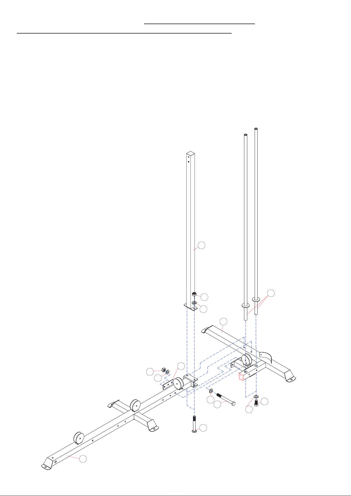
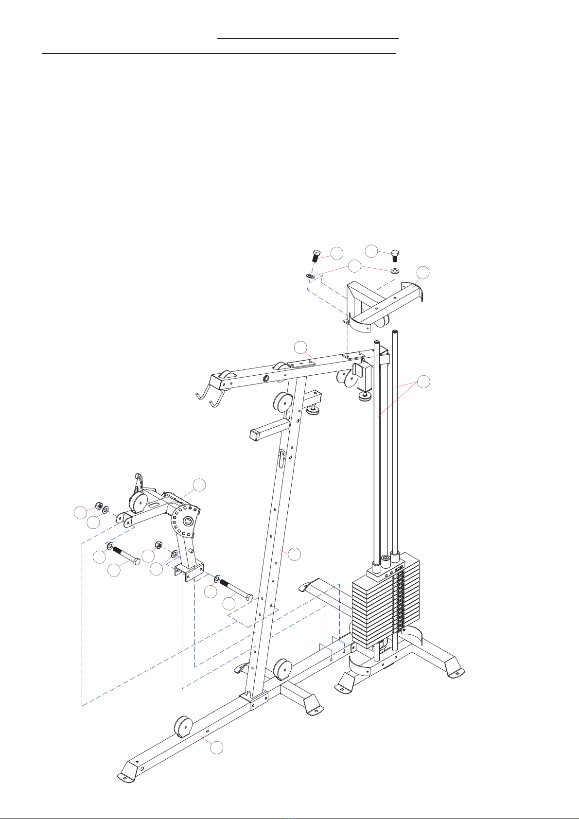
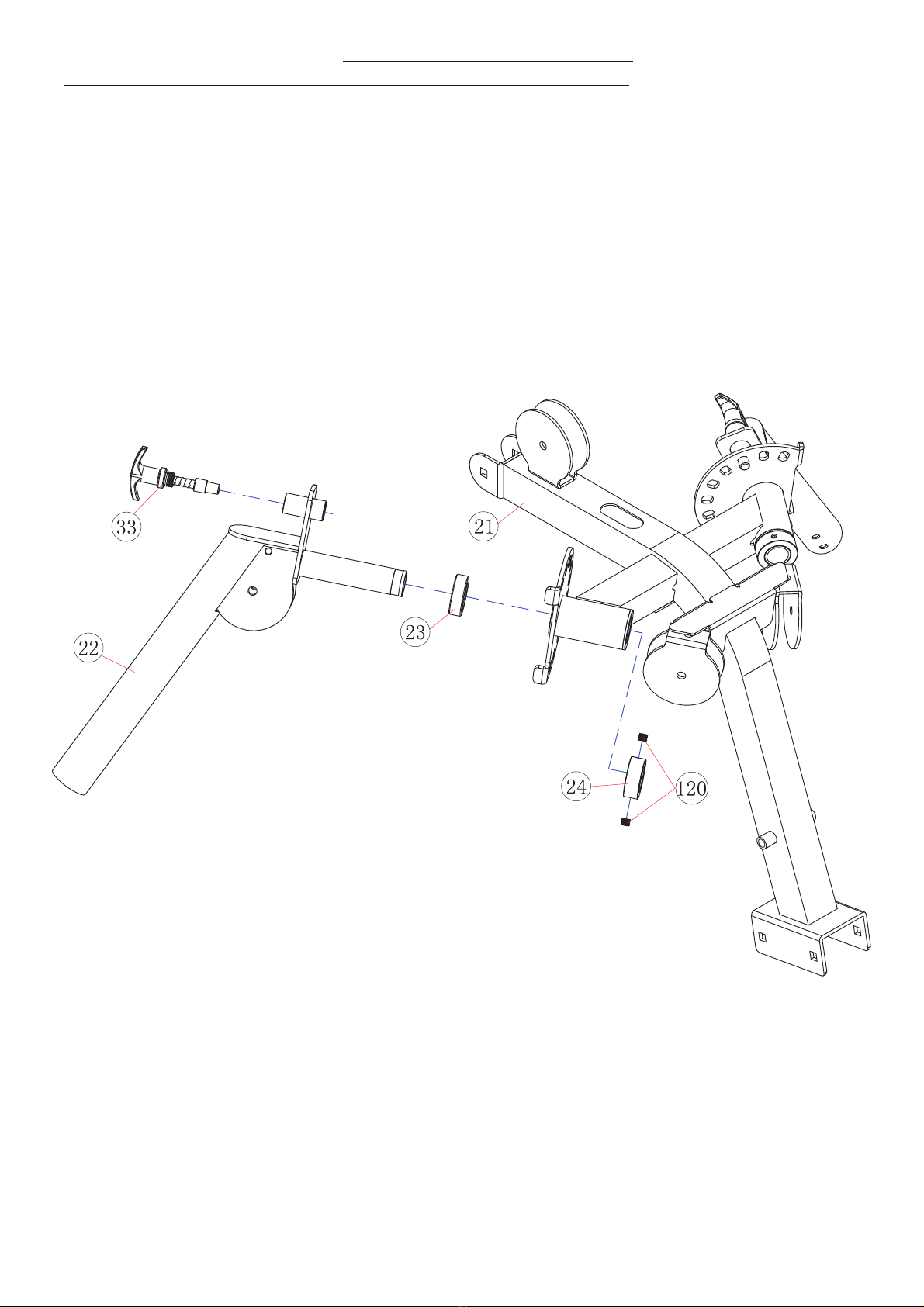
Follow the instructions and consult both the individual assembly pages and the overall expanded views of the
equipment.
Certain parts may arrive pre-assembled from the factory.
It is the owner’s responsibility to ensure that all users of this unit have read the owner’s manual and are familiar with
the safety precautions.
SAFETY PRECAUTIONS
·Highly recommended for two or more people to assemble the equipment to avoid injury.
·Assemble the equipment on a flat level surface.
·Consider placing a mat under the equipment to protect your floor.
·Wear appropriate footwear and clothing during assembly and use.
·Only tighten nuts and bolts by hand until the whole equipment is assembled.
·Ensure you correctly orientate each piece before attaching.
·Do not allow children and pets to be unsupervised around the assembly or usage of this equipment.
·Ensure all parts are in full working order before use.
·Only one person should use the machine at any one time.
·Do not use the equipment outdoors or around water.
·Keep hair, fingers or clothing away from moving parts.
·Only use attachments recommended by the manufacturer.
·Never operate if any parts are not functioning correctly.
·Always correctly stretch and warm up before using the equipment.
·Stop immediately if your experience any pain, dizziness or nausea. See a doctor at once.
PLEASE NOTE: Descriptions of pieces as LEFT and RIGHT are from the point of view of standing behind the
equipment facing towards the front.
BEFORE STARTING ANY EXERCISE PROGRAM, CONSULT YOUR DOCTOR. ESPECIALLY IF YOU ARE OVER
THE AGE OF 35 OR HAVE PRE-EXISTING HEALTH PROBLEMS.
READ ALL INSTRUCTIONS BEFORE ASSEMBLING OR USING ANY FITNESS EQUIPMENT.
tASSUME NO RESPONSIBILITY FOR PERSONAL INJURY OR PROPERTY DAMAGE SUSTAINED BY OR
THROUGH THE USE OF THIS PRODUCT.
SAVE THESE INSTRUCTIONS
Tools provided with &&ͲXϰ
Allen wrench 6 X2 Allen wrench 5 X1 Allen wrench 4 X1
## #

3
3$576/,67
.(<12 3$57'(6&5,37,21 63(& 47<
5HDU%DVH)UDPH
5HDU9HUWLFDO)UDPH
)URQW9HUWLFDO)UDPH
8SSHU)UDPH
*XLGH5RG
)URQWVXSSRUW)UDPH
6HDW6XSSRUW
8SSHU*XLGH5RG)UDPH
)URQW3UHVV%DVH
)RRW3ODWH
%HQGLQJ)RDPIUDPH
0LG$[OH ¶hh0
%DVH)UDPH
/DW%DU
6KLYHU%DU
%XVKLQJ ¶h¶h
$GMXVWDEOH3XOOH\%UDFNHW
3XOOH\%UDFNHW
$GMXVWDEOH%DFNUHVW6XSSRUW
%DFNUHVW6XSSRUW
%XWWHUIO\6XSSRUW
%XWWHUIO\
%XVKLQJ ¶h¶h
%XWWHUIO\6OHHYH ¶h¶hh0
%XVKLQJ ¶h¶h¶h
/HJ'HYHORSHU
:HLJKW6WDFN&RYHU h5h
$GMXVWDEOH%ROW
6KHOOEHDULQJ ¶h¶h¶h
)URQW&RYHU hh
8SSHU$[OH
)RRW3ODWH7XEH Ïhh
/RFN.QRE
%XVKLQJ ¶h¶h¶h
+DQGOH*ULS ¶h
/RQJ)RDPIUDPH
6KRUW)RDPIUDPH
%UDFNHW hhh
)URQW3UHVV
3XOO&DEOH /
%XWWHUIO\&DEOH /
&RQQHFWDEOH&DEOH /
8SSHU&DEOH /
6KRUW&RQQHFWDEOH&DEOH /
6HDW3DG hh

4
8SSHU GUDR%WVHUNFD% hh
GUDR%WVHUNFD%UHZR/ hh
HOIID%PDR) ¶h
WHNFDU%\HOOX3JQLZ6PU$
(QG&DS ƶh
%UDFNHW hh
%UDFNHW hh
:KHHO ¶h
%XVKLQJ ¶h¶ h
(QG&DS ƶ
(QG&DS ƶ
(QG&DS ƶh
(QG&DS 
5XEEHU%XPSHU ¶h¶ h
(QG&DS ƶhƶ
(QG&DS 
:HLJKW6HOHFWRU3LQ
6WRSSHU ƶ
(QG&DS 
5XEEHU%XPSHU ¶h¶ h
PHW6URWFHOH6 hh
HWDO3WKJLH: hh
/RFN.QRE 0h
)RDP5ROO ¶h¶ h
5LYHW ¶h
SLU*HOGQD+WURK6 ¶h
/RQJ+DQGOH*ULS ¶h
GR5URWFHOH6 ¶h
$[OH ¶h0h
0DJQHW ¶h¶ h
JQLUDH%OOD%HYRRU* =5
JQLUDHEOODEWVXUK7
+RRN 
3XOOH\ 
6WUDS
HOGQD+HOJQL6HOEDWVXMG$
SDUW6HONQ$
JQLKVX%\HOOX3
+(56
3+
¶h
h
15
6OHHYH ƶhƶ
JQLKVX%UHQLDWH5HOED& ¶h
UHQLDWH5HOED&
&RYHU&DS 0
&RYHU&DS 0
/RQJ&KDLQ OLQN
QLDK&WURK6 OLQN
:DVKHU
:DVKHU
:DVKHU ¶h¶ h

5
94 Washer 38× 13×3 2
95 Serrated Nut M24×1 4
96 Aircraft Nut M8 2
97 Aircraft Nut M10 47
98 Hex Bolt M10×16 5
99 Hex Bolt M10×20 10
100 Hex Bolt M10×25 2
101 Hex Bolt M10×45 4
102 Hex Bolt M10×50 4
103 Hex Bolt M10×55 11
104 Hex Bolt M10×65 2
105 Hex Bolt M10×70 1
106 Hex Bolt M10×75 6
107 Hex Bolt M10×80 1
108 Hex Bolt M10×85 2
109 Hex Bolt M10×95 8
110 Hex Bolt M10×135 1
111 Hex Bolt M10×170 1
112 Allen Bolt M10×190 2
113 Hex Bolt M10×90 1
114 Hex Bolt M8×40 2
115 Allen Bolt M8×9 12
116 Allen Bolt M8×45 2
117 Allen Bolt M8×90 2
118 Allen Bolt M8×25 2
119 Allen Bolt M10×16 4
120 Allen Bolt M8×8 4
121 Allen Bolt M8×16 3
122 Philips Screw M6X16 1
123 Carriage Bolt M10×80 2
124 Bracket 120×50×5 2
125 Hexnut M12 2

Descriptions of LEFT and RIGHT are from the point of view of standing behind the equipment facing the front 6
ASSEMBLY DIAGRAM 1 USE A PARTNER TO HELP WITH THIS STEP
REMEMBER: Only hand tighten all nuts and bolts until whole &&ͲXϰis assembled
1. Ensuring correct orientation, slot the bracket on the end of BASE FRAME (13) over the bolt holes in the centre of the
REAR BASE FRAME (1)
2. Position the REAR VERTICAL FRAME (2) over the same point and attach all three parts together from underneath
using two CARRIAGE BOLT M10X80 (123), two WASHER10 (92) and two AIRCRAFT NUT M10 (97)
3. Position a BRACKET (124) on the right side of the BASE FRAME (13) level with the rear pulley bracket.
4. Connect the BRACKET (124), the BASE FRAME (13) and the REAR BASE FRAME (1) together using two HEX BOLT
M10X95 (109), four WASHER10 (92) and two AIRCRAFT NUT M10 (97)
5. Slot the two GUIDE RODS (5) into the slots on the REAR BASE FRAME (1) and connect from underneath using two HEX
BOLT M10X20 (99) and two WASHER10 (92)

Descriptions of LEFT and RIGHT are from the point of view of standing behind the equipment facing the front 7
ASSEMBLY DIAGRAM 2 USE A PARTNER TO HELP WITH THIS STEP
REMEMBER: Only hand tighten all nuts and bolts until whole &&ͲXϰis assembled
1. Slide a RUBBER BUMPER (65) down onto each GUIDE ROD (5) ensuring they are level with each other.
2. Position the fourteen WEIGHT PLATES (67) onto the GUIDE RODS (5) ensuring the holes for the adjustor pin are facing
outward
3. Connect the SELECTOR ROD (73) to the SELECTOR STEM (66) using a HEX BOLT M10X90 (113) and an AIRCRAFT NUT
M10 (97).
4. Slide the connected selector parts (73&66) down over the GUIDE RODS (5) and into the centre of the WEIGHT PLATES
(67)
.*/%
.*/%
.*/%
.*/%
.*/%
.*/%
.*/%
.*/%
.*/%
.*/%
.*/%
.*/%
.*/%
.*/%
.*/%

Descriptions of LEFT and RIGHT are from the point of view of standing behind the equipment facing the front 8
ASSEMBLY DIAGRAM 3 USE A PARTNER TO HELP WITH THIS STEP
REMEMBER: Only hand tighten all nuts and bolts until whole &&ͲXϰis assembled
1. Ensuring correct orientation, position the top of the FRONT VERTICAL FRAME (3) under the centre of the UPPER
FRAME (4). Place a BRACKET (51) above the same point and connect all parts together using two HEX BOLT M10X75
(106), four WASHER10 (92) and two AIRCRAFT NUT M10 (97)
2. Screw an ADJUSTABLE BOLT (28) and an HEXNUT M12 (125)
into the small horizontal post at the top of the
FRONT VERTICAL FRAME (3). Screw an ADJUSTABLE BOLT (28) and an HEXNUT M12 (125) into the small vertical
post near the rear of the UPPER FRAME (4)
3. Lift the assembled parts (3&4) and position them, so the base of the FRONT VERTICAL FRAME (3) slots over the
central bolt holes in the BASE FRAME (13) and the rear end of the UPPER FRAME (4) slots over the bolt holes at the
top of the REAR VERTICAL FRAME (2)
4. Connect the FRONT VERTICAL FRAME (3) to the BASE FRAME (13) using two HEX BOLT M10X95 (109), four WASHER10
(92) and two AIRCRAFT NUT M10 (97)
5. Connect the UPPER FRAME (4) to the REAR VERTICAL FRAME (2) through a BRACKET (38) placed over the rear using a
HEX BOLT M10X70 (105) and a WASHER10 (92) in the upper hole, and a HEX BOLT M10X75 (106), two WASHER10 (92)
and an AIRCRAFT NUT M10 (97) in the lower hole.

Descriptions of LEFT and RIGHT are from the point of view of standing behind the equipment facing the front 9
ASSEMBLY DIAGRAM 4 USE A PARTNER TO HELP WITH THIS STEP
REMEMBER: Only hand tighten all nuts and bolts until whole &&ͲXϰis assembled
1. Ensuring correct orientation, position the BUTTERFLY SUPPORT (21) between the BASE FRAME (13) and the rear of
the FRONT VERTICAL FRAME (3)
2. Connect the BUTTERFLY SUPPORT (21) to the BASE FRAME (13) using two HEX BOLT M10X95 (109), four WASHER10
(92) and two AIRCRAFT NUT M10 (97)
3. Connect the BUTTERFLY SUPPORT (21) to the FRONT VERTICAL FRAME (3) using HEX BOLT M10X75 (106), two
WASHER10 (92) and an AIRCRAFT NUT M10 (97)
4. Ensuring correct orientation, position the UPPER GUIDE ROD FRAME (8) over the top of the GUIDE RODS (5) and the
UPPER FRAME (4)
5. Connect the UPPER GUIDE ROD FRAME (8) to the GUIDE RODS (5) using two HEX BOLT M10X20 (99) and two
WASHER10 (92). Connect the UPPER GUIDE ROD FRAME (8) to the UPPER FRAME (4) using two HEX BOLT M10X16
(98) and two WASHER10 (92)

Descriptions of LEFT and RIGHT are from the point of view of standing behind the equipment facing the front 10
ASSEMBLY DIAGRAM 5 USE A PARTNER TO HELP WITH THIS STEP
REMEMBER: Only hand tighten all nuts and bolts until whole &&ͲXϰis assembled
1. Insert a BUSHING (34) into each open end of the BUTTERFLY SUPPORT (21) posts. (See the exploded diagram for more
detail, skip this step if pre-assembled)
2. Attach a BUSHING (23) to the short end of both BUTTERFLY (22) and slot them into position on each side of the
BUTTERFLY SUPPORT (21)
3. Connect the BUTTERFLY (22) to the BUTTERFLY SUPPORT (21) on both sides using a BUTTERFLY SLEEVE (24) and two
ALLEN BOLTS M8X8 (120) on each.
4. Slot a LOCK KNOB (33) into position on the front of each BUTTERFLY (22) to angle the butterflies equally on each side.

Descriptions of LEFT and RIGHT are from the point of view of standing behind the equipment facing the front 11
ASSEMBLY DIAGRAM 6 USE A PARTNER TO HELP WITH THIS STEP
REMEMBER: Only hand tighten all nuts and bolts until whole &&ͲXϰis assembled
1. Ensuring correct orientation, position the ADJUSTABLE BACKREST SUPPORT (19) over the mid-point bolt holes on the
right side of the FRONT VERTICAL FRAME (3) and a BRACKET (52) at the same point on the left.
2. Connect all parts using two HEX BOLT M10X75 (106), four WASHER10 (92) and two AIRCRAFT NUT M10 (97)
3. Attach a SLEEVE (84) to the rear of the ADJUSTABLE BACKREST SUPPORT (19) (Skip this step if pre-assembled)
4. Position the FRONT SUPPORT FRAME (6) so the vertical post sits to the right of the BASE FRAME (13) and the rear
bracket lines up with the lowest bolt holes on the FRONT VERTICAL FRAME (3)
5. Connect the FRONT SUPPORT FRAME (6) to the BASE FRAME (13) using a HEX BOLT M10X135 (110), two WASHER10
(92) and an AIRCRAFT NUT M10 (97)
6. Connect the FRONT SUPPORT FRAME (6) to the FRONT VERTICAL FRAME (3) and through a BRACKET (124) positioned
at the rear, using two HEX BOLT M10X95 (109), four WASHER10 (92) and two AIRCRAFT NUT M10 (97)
7. Assemble the AXEL (74) using two GROOVE BALL BEARING (76) and two SHELL BEARING (29). Insert a RUBBER
BUMPER (59) into the front of the LEG DEVELOPER (26) using a PHILIPS SCREW (122) (See the exploded diagram for
more detail, skip this step if pre-assembled)
8. Slot the AXEL (74) through the front of the FRONT SUPPORT FRAME (6). Position the LEG DEVELOPER (26) over the
ends of the AXEL (74), connecting with two ALLEN BOLT M10X16 (119) and two WASHER10 (92)
9. Clip a LOCK KNOB (68) to the right side of the ADJUSTABLE BACKREST SUPPORT (19) and also to the top right of the
vertical post on the FRONT SUPPORT FRAME (6)

Descriptions of LEFT and RIGHT are from the point of view of standing behind the equipment facing the front 12
ASSEMBLY DIAGRAM 7 USE A PARTNER TO HELP WITH THIS STEP
REMEMBER: Only hand tighten all nuts and bolts until whole &&ͲXϰis assembled
1. Attach the FRONT COVER (30) to the FRONT PRESS BASE (9) using six RIVETS (70). Insert a BUSHING (25) into each
side of the base. (See the exploded diagram for more detail, skip this step if pre-assembled)
2. Insert a HANDLE GRIP (35) into each side of the FRONT PRESS (39). Insert an END CAP (61) tothe end of each handle
and an END CAP (64) on the ends of the FRONT PRESS (39). Insert a MAGNET (75) into each rear side of the BUTTERFLY
(39) (See the exploded diagram for more detail, skip this step if pre-assembled)
3. Insert a BUSHING (54) into each side of the axel hole near the front of the UPPER FRAME (4). Ensuring correct
orientation, position the FRONT PRESS BASE (9) over the axel hole.
4. Slide the UPPER AXEL (31) through the FRONT PRESS BASE (9) and the UPPER FRAME (4) from left to right. Connect
using a HEX BOLT M10X16 (98) and a WASHER (93)
5. Ensuring correct orientation, position the FRONT PRESS (39) over the holes at the base of the FRONT PRESS BASE (9)
6. Slide the MID AXEL (12) through the FRONT PRESS (39) and the FRONT PRESS BASE (9). Connect using two HEX BOLT
M10X16 (98) and two WASHER (93). Insert two ALLEN BOLT M8X16 (121) to the rear holes on the BUTTERFLY (39)
7. Connect a LOCK KNOB (33) through the upper right side of the FRONT PRESS (39)
8. Behind each butterfly handle, connect vertically upward a SHORT CONNECTABLE CABLE (44), using a HEX BOLT
M10X25 (100), two WASHER10 (92) and an AIRCRAFT NUT M10 (97) on each side.

Descriptions of LEFT and RIGHT are from the point of view of standing behind the equipment facing the front 13
ASSEMBLY DIAGRAM 8 USE A PARTNER TO HELP WITH THIS STEP
REMEMBER: Only hand tighten all nuts and bolts until whole &&ͲXϰis assembled
1. Slide a FOAM ROLL (69) onto each end of the BENDING FOAM FRAME (11) and secure using a FOAM BAFFLE (48), a
WASHER10 (92) and a HEX BOLT M10X20 (99) on each side.
2. Ensuring correct orientation, Connect the assembled BENDING FOAM FRAME (11) to the FRONT VERTICAL FRAME (3)
using two ALLEN BOLT M10X16 (119) and two WASHER10 (92)
3. Insert the LONG FOAM FRAME (36) into the upper hole on the FRONT SUPPORT FRAME (6)
4. Insert the SHORT FOAM FRAME (37) into the lower hole on the LEG DEVELOPER (26)
5. On each end of both frames (36&37) slide a FOAM ROLL (69) and secure using a FOAM BAFFLE (48), a WASHER10 (92)
and a HEX BOLT M10X20 (99) on each

Descriptions of LEFT and RIGHT are from the point of view of standing behind the equipment facing the front 14
ASSEMBLY DIAGRAM 9 USE A PARTNER TO HELP WITH THIS STEP
REMEMBER: Only hand tighten all nuts and bolts until whole &&ͲXϰis assembled
1. Attach the UPPER BACKREST BOARD (46) to the FRONT VERTICAL FRAME (3) using two ALLEN BOLT (117) and two
WASHER8 (91)
2. Attach the LOWER BACKREST BOARD (47) to the BACK REST SUPPORT (20) using two ALLEN BOLT M8X25 (118) and
two WASHER8 (91)
3. Ensuring correct orientation, slot the assemble support and board (20&47) into the ADJUSTABLE BACKREST SUPPORT
(19), securing it with the pre-positioned LOCK KNOB (64)
4. Attach SEAT PAD (45) to the SEAT SUPPORT (7) using two ALLEN BOLT M8X45 (116) and two WASHER8 (91)
5. Insert a SLEEVE (84) and an END CAP (56) into the base of SEAT SUPPORT (7) (Skip this step if pre-assembled)
6. Slot the assembled seat (45&7) into the hollow post on the FRONT SUPPORT FRAME (6), securing it with the pre-
positioned LOCK KNOB (64)
7. Position the FOOT PLATE (10) over the holes at the front of the BASE FRAME (13). Slide the FOOT PLATE TUBE (32)
through the plate and the frame and secure from above with an ALLEN BOLT M8X16 (121)

Descriptions of LEFT and RIGHT are from the point of view of standing behind the equipment facing the front 15
ASSEMBLY DIAGRAM 10 USE A PARTNER TO HELP WITH THIS STEP
REMEMBER: Only hand tighten all nuts and bolts until whole &&ͲXϰis assembled
(HINT: Work your way from the stoppered end of the cable to the other, connecting one pulley at a time and ensuring
everything is positioned correctly before continuing. Ensure the cable retainers are all correctly angled)
1. Position the stopped end of the UPPER CABLE (43) underneath the front of the UPPER FRAME (4), draw the rest of the
cable up through the pulley bracket.
2. Insert a PULLEY (79) into the pulley bracket, ensuring the cable runs up the front and over the pulley. Attach using a
HEX BOLT M10X85 (108), two WASHER10 (92) and an AIRCRAFT NUT M10 (97)
3. Draw the cable along and down through the next pulley bracket on the UPPER FRAME (4)
4. Insert a PULLEY (79) into the pulley bracket, ensuring the cable runs over the top and down the back of the pulley.
Attach using a HEX BOLT M10X85 (108), two WASHER10 (92) and an AIRCRAFT NUT M10 (97)
5. Draw the cable forward through the top of the FRONT PRESS BASE (9)
6. Slide an ALLEN BOLT M10X190 (112) through a WASHER10 (92) and into the top right hole of the FRONT PRESS BASE
(9). Feed onto the bolt (in correct order), two WASHER10 (92), two CABLE RETAINER (86), two CABLE RETAINER
BUSHING (85) and a PULLEY (79). Slide the bolt out the top left hole, secure using a WASHER10 (92) and an AIRCRAFT
NUT (97)
7. Ensure the cable runs over the top of the pulley, then draw the cable backward into the pulley bracket on the FRONT
VERTICAL FRAME (3) DIAGRAM C
8. Insert a PULLEY (79) into the bracket, ensuring the cable runs over and down the rear of the pulley. Using a HEX BOLT
M10X55 (103), connect a WASHER10 (92), a CABLE RETAINER (86), and a CABLE RETAINER BUSHING (85) to both
outer sides of the pulley bracket. Secure the whole assembly with an AIRCRAFT NUT M10 (97)
9. Draw the cable forward again, through the FRONT PRESS BASE (9)
10. Slide an ALLEN BOLT M10X190 (112) through a WASHER10 (92) and into the lower right hole of the FRONT PRESS
BASE (9). Feed onto the bolt (in correct order), two WASHER10 (92), two CABLE RETAINER (86), two CABLE RETAINER
BUSHING (85) and a PULLEY (79). Slide the bolt out the lower left hole, secure using a WASHER10 (92) and an
AIRCRAFT NUT (97)
11. Ensure the cable runs over the top of the pulley, then draw the cable under and backward and feed it through the
pulley slot on the FRONT VERTICAL FRAME (3) DIAGRAM C
12. Insert a PULLEY (79) into the slot ensuring the cable runs over the top of the pulley. Attach using a HEX BOLT M10X65
(104), two PULLEY BUSHING (83) and an AIRCRAFT NUT M10 (97)
13. Assemble the two hanging pulley brackets DIAGRAM A & B. For each, insert a PULLEY (79) into the top bolt holes of
ADJUSTABLE PULLEY BRACKET (17).Using a HEX BOLT M10X55 (103), connect a WASHER10 (92), a CABLE RETAINER
(86), and a CABLE RETAINER BUSHING (85) to both outer sides of the pulley bracket. Secure the whole assembly with
an AIRCRAFT NUT M10 (97). Ensuring correct orientation, attach them to the two pre-positioned ADJUSTABLE BOLTS
(28) under the upper frame.
14. Draw the cable downward and feed it under the assembled hanging pulley A
15. Draw the cable upward to the pulley bracket under the rear of the UPPER FRAME (4) DIAGRAM D. Insert a PULLEY
(79) into the pulley bracket. Using a HEX BOLT M10X80 (107), connect a WASHER10 (92), a CABLE RETAINER (86), and
a CABLE RETAINER BUSHING (85) to the left outer side of the pulley bracket. Leave the other side bare and unsecured
until the next stage of assembly in STEP 11
16. Ensure the cable runs over the top of the pulley, then draw the cable downward and feed it under the assembled
hanging pulley B
17. Draw the cable up into the pulley bracket under the UPPER GUIDE ROD FRAME (8). Insert a PULLEY (79) into the
pulley bracket. Using a HEX BOLT M10X55 (103), connect a WASHER10 (92), a CABLE RETAINER (86), and a CABLE
RETAINER BUSHING (85) to both outer sides of the pulley bracket. Secure the whole assembly with an AIRCRAFT NUT
M10 (97). Ensure the cable runs over the pulley from right to left.
18. Draw the cable downwards, pass it through the ring on the end of the WEIGHT SELECTOR PIN (62) and connect the
end to the top of the SELECTOR ROD (73)

Descriptions of LEFT and RIGHT are from the point of view of standing behind the equipment facing the front 16
ASSEMBLY DIAGRAM 1USE A PARTNER TO HELP WITH THIS STEP
REMEMBER: Only hand tighten all nuts and bolts until whole &&ͲXϰis assembled
$
$
%
%
&
&
'
'

Descriptions of LEFT and RIGHT are from the point of view of standing behind the equipment facing the front 17
ASSEMBLY DIAGRAM 1USE A PARTNER TO HELP WITH THIS STEP
REMEMBER: Only hand tighten all nuts and bolts until whole &&ͲXϰis DVVHPEOHG
(HINT: Work your way from the stoppered end of the cable to the other, connecting one pulley at a time and ensuring
everything is positioned correctly before continuing. Ensure the cable retainers are all correctly angled)
1. Position the stoppered end of CONNECTABLE CABLE (42) in the rear left pulley bracket on the REAR BASE FRAME (1)
2. Insert a PULLEY (79), ensuring the cable runs under the pulley. Attach using a HEX BOLT M10X50 (102), a WASHER10
(92), a CABLE RETAINER (86), and a CABLE RETAINER BUSHING (85); on the front outer side of the bracket; and a
WASHER10 (92) and an AIRCRAFT NUT M10 (97) on the rear outer side.
3. Draw the cable upward to the ADJUSTABLE PULLEY BRACKET (17) under the left rear of the UPPER FRAME (4)
DIAGRAM A. Insert a PULLEY (79) into a lower bolt hole, ensuring the cable runs over the pulley. Attach using a HEX
BOLT M10X55 (103),with a WASHER10 (92), a CABLE RETAINER (86), and a CABLE RETAINER BUSHING (85) on each
outer side of the bracket. Secure with an AIRCRAFT NUT M10 (97)
4. Draw the cable downward to the pulley bracket at the rear of the BASE FRAME (13)
5. Insert a PULLEY (79) into the bracket, ensuring the cable runs under the pulley from left to right. Attach using a HEX
BOLT M10X55 (103), with a WASHER10 (92), a CABLE RETAINER (86), and a CABLE RETAINER BUSHING (85) on each
outer side of the bracket. Secure with an AIRCRAFT NUT M10 (97)
6. Draw the cable upward to the pulley bracket under the rear of the UPPER FRAME (4) DIAGRAM B it will still be
unsecured from the previous stage (STEP 10)
7. Insert a second PULLEY (79) to the right hand of the one in use, so there are now two pulleys within the bracket.
Ensure the cable runs over the new pulley from rear to front.
8. Slide the pre-positioned bolt through both pulleys and attach a CABLE RETAINER BUSHING (85), a CABLE RETAINER
(86), a WASHER10 (92) and an AIRCRAFT NUT (97) to the outer right side of the bracket.
9. Attach a PULLEY BRACKET (18) to the upper end of the CONNECTABLE CABLE (42)
$
$
%
%
67(3
67(3
67(3
67(3
67(3

Descriptions of LEFT and RIGHT are from the point of view of standing behind the equipment facing the front 18
ASSEMBLY DIAGRAM 1USE A PARTNER TO HELP WITH THIS STEP
REMEMBER: Only hand tighten all nuts and bolts until whole &&ͲXϰis assembled
(HINT: Work your way from one end of the cable to the other, connecting one pulley at a time and ensuring
everything is positioned correctly before continuing. Ensure the cable retainers are all correctly angled)
1. IMPORTANT: If you undo the end of the PULLCABLE (40) during assembly, it is very important to ensure that you
securely re-tighten the nuts at the ends of the cable before use . Use the diagram as a reference.
2. Position one end of the cable in the pulley bracket on the front of the LEG DEVELOPER (26)
3. Insert a PULLEY (79) into the bracket, ensuring the cable runs under the pulley from front to back. Attach using a HEX
BOLT M10X50 (102), with a WASHER10 (92), a CABLE RETAINER (86), and a CABLE RETAINER BUSHING (85) on each
outer side of the bracket. Secure with an AIRCRAFT NUT M10 (97)
4. Draw the cable backward, through the pulley bracket at the front of the BASE FRAME (13) DIAGRAM D
5. Insert a PULLEY (79) into the bracket, ensuring the cable runs under the pulley. Attach using a HEX BOLT M10X55
(103), with a WASHER10 (92), a CABLE RETAINER (86), and a CABLE RETAINER BUSHING (85) on each outer side of the
bracket. Secure with an AIRCRAFT NUT M10 (97)
6. Draw the cable backward, through the pulley bracket in the middle of the BASE FRAME (13) DIAGRAM C
7. Insert a PULLEY (79) into the bracket, ensuring the cable runs under the pulley. Attach using a HEX BOLT M10X55
(103), with a WASHER10 (92), a CABLE RETAINER (86), and a CABLE RETAINER BUSHING (85) on each outer side of the
bracket. Secure with an AIRCRAFT NUT M10 (97)
8. Draw the cable upward to the ADJUSTABLE PULLEY BRACKET (17) at the top of the FRONT VERTICAL FRAME (3)
DIAGRAM A. Insert a PULLEY (79) into a lower bolt hole, ensuring the cable runs over the pulley from rear to front.
Attach using a HEX BOLT M10X55 (103), with a WASHER10 (92), a CABLE RETAINER (86), and a CABLE RETAINER
BUSHING (85) on each outer side of the bracket. Secure with an AIRCRAFT NUT M10 (97)
9. Draw the cable downward into the pulley bracket on top of the BUTTERFLY SUPPORT (21) DIAGRAM B
10. Insert a PULLEY (79) into the bracket, ensuring the cable runs under the pulley from rear to front. Attach using a HEX
BOLT M10X55 (103), with a WASHER10 (92), a CABLE RETAINER (86), and a CABLE RETAINER BUSHING (85) on each
outer side of the bracket. Secure with an AIRCRAFT NUT M10 (97)
11. Draw the cable upwards and forward through the slit in the FRONT VERTICAL FRAME (3)
12. Insert a PULLEY (79) into the slit, ensuring the cable runs over the pulley. Attach using a HEX BOLT M10X65 (104), two
PULLEY BUSHING (83) and an AIRCRAFT NUT M10 (97)

Descriptions of LEFT and RIGHT are from the point of view of standing behind the equipment facing the front 19
ASSEMBLY DIAGRAM 1USE A PARTNER TO HELP WITH THIS STEP
REMEMBER: Only hand tighten all nuts and bolts until whole &&ͲXϰis assembled
$
$
%
%
&
&
'
'

Descriptions of LEFT and RIGHT are from the point of view of standing behind the equipment facing the front 20
ASSEMBLY DIAGRAM 1USE A PARTNER TO HELP WITH THIS STEP
REMEMBER: Only hand tighten all nuts and bolts until whole &&ͲXϰis assembled
(HINT: Work your way from one end of the cable to the other, connecting one pulley at a time and ensuring
everything is positioned correctly before continuing. Ensure the cable retainers are all correctly angled)
1. IMPORTANT: When you undo the ends of the BUTTERFLY CABLE (41) during assembly, it is very important that you
securely re-tighten the nuts at the ends of the cable before use. Use the diagram as a reference.
2. Assemble the ARM SWING PULLEY BRACKET (49) by attaching two THRUST BALL BEARINGS (77), a BUSHING (16) and
two SERRATED NUTS (95) (For details, view the expanded diagram –skip this step if pre-assembled)
3. Position one end of the BUTTERFLY CABLE (41) at the entrance of a ARM SWING PULLEY BRACKET (49), feed the cable
through the bracket. Insert a WHEEL (53) at the entrance to the bracket. Attach using a HEX BOLT M8X40 (114), two
WASHER8 (91) and an AIRCRAFT NUT M8 (96)
4. Insert a PULLEY (79) into the bracket; ensure the cable runs over the pulley. Attach using a HEX BOLT M10X45 (101),
with a WASHER10 (92) on each outer side of the bracket. Secure with an AIRCRAFT NUT M10 (97)
5. Thread the cable through the left BUTTERFLY (22) to the rear of the BUTTERFLY SUPPORT (21)
6. Slot the ARM SWING PULLEY BRACKET (49) with the inserted cable, into the left BUTTERFLY (22) and attach using two
ALLEN BOLT M8X9 (115) and two WASHER8 (91)
7. Insert a PULLEY (79) into the corner pulley bracket on the left BUTTERFLY (22). Attach using a HEX BOLT M10X45
(101), two WASHER10 (92) and an AIRCRAFT NUT M10 (97)
8. Insert a PULLEY (79) into the pulley bracket at the rear left of BUTTERFLY SUPPORT (21). Ensure the cable runs over
the top of the pulley. Attach using a HEX BOLT M10X50 (102), with a WASHER10 (92), a CABLE RETAINER (86), and a
CABLE RETAINER BUSHING (85) on the outer side of the bracket. Secure with an WASHER10 (92) and an AIRCRAFT
NUT M10 (97)
9. Onto HEX BOLT M10X170 (111) thread (in correct order), two WASHER10 (92), two CABLE RETAINER (86), two CABLE
RETAINER BUSHING (85) and a PULLEY (79).
10. Insert the assembled HEX BOLT M10X170 (111) through the base of the BUTTERFLY SUPPORT (21) and then thread on
(in correct order), two WASHER10 (92), two CABLE RETAINER (86), two CABLE RETAINER BUSHING (85) and a PULLEY
(79). Secure with an AIRCRAFT NUT M10 (97)
11. Draw the cable down and under the left pulley at the base of the BUTTERFLY SUPPORT (21), ensuring the cable runs
from front to rear.
12. Draw the cable up to the PULLEY BRACKET (18) attached to end of the CONNECTABLE CABLE (42)
13. Insert a PULLEY (79) into the pulley bracket, ensuring the cable runs over the pulley from left to right. Attach using a
HEX BOLT M10X55 (103), with two WASHER10 (92), two CABLE RETAINER (86) and two CABLE RETAINER BUSHING
(85) on each outer side of the bracket. Secure using an AIRCRAFT NUT M10 (97)
14. Draw the cable down and under the right pulley at the base of the BUTTERFLY SUPPORT (21), ensuring the cable runs
from rear to front.
15. Repeat the required assembly steps in reverse to thread the cable through the right hand side of the butterfly.
This manual suits for next models
1
Table of contents
Other FRENCH FITNESS Elliptical Trainer manuals