FRER IEC61850 Instruction sheet

IEC61850 GATEWAY
CONFIGURATION MANUAL
No. Ipm0218_3
Pag./Page 1 di/of 44
3 05/07/18 FW 3.0.0.3 edition S. Isella A. Miori
2 14/03/18 General revision S. Isella A. Miori
1 21/12/16 General revision S. Isella A. Miori
0 14/09/16 First edition S. Isella A. Miori
Rev. Data / Date Descrizione / Description Preparata / Prepared Approvata / Approved
1. GENERAL DESCRIPTION
1.1 Introduction
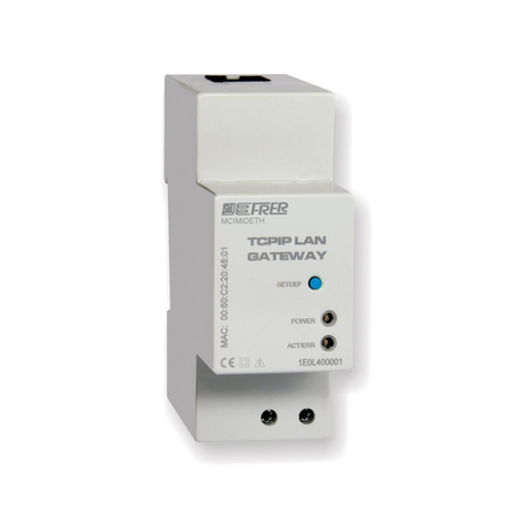
Some FRER meters can be optionally equipped with an integrated IEC61850 Gateway or, as an alternative, can use
an external IEC61850 / Modbus RTU Gateway.
1.2 Additional option
As an additional option, on the integrated Gateway, a Master RS485 Modbus interface can also be installed,
expanding the Gateway functionality to other meters only equipped with a Slave RS485 Modbus interface.
1.3 Available Versions
Both Gateway types, integrated and external, are available in different combinations regarding the maximum number
of meters that can be connected, the Set of available measured quantities, the number of Data Sets and Report
Control Blocks included in the default configuration, and allowed as maximum in each IED.
Max
Meters
Set of
measured
quantities (1)
Default Data
Sets for the
Gateway L.D.
(1)
Default Data
Sets for each
Meter L.D. (1)
Default Data
Sets for each
IED
Default RCB's
for each Data
Set (1)
Default RCB's
for each IED
Max allowed
Data Sets for
each IED
Max allowed
RCB's for each
IED
1 Full 1 4 5 4 20 6 24
4 Full 0 3 12 2 24 12 24
6 Reduced 0 3 18 1 18 18 24
Note (1): See chapter 5 "IEC61850 SERVER" for further details
1.4 Special considerations regarding the measurements updating time
The IEC61850 Gateway performs 3 basic operations in sequence:
Fetching of the measurements data from the meter.
Evaluating if the measurements data have changed more than the preset deadbands and, in case, updating
the relevant Data Sets.
Sending the Reports to the subscribed clients, according to the triggering options they have chosen.
This sequence is repeated, in a cyclical way, for each meter connected to the Gateway.
The time needed to complete the sequence for a single meter, depends on many factors, but the most relevant are:

IEC61850 GATEWAY
CONFIGURATION MANUAL
No. Ipm0218_3
Pag./Page 2 di/of 44
the variability of the measured quantities
the number of subscribed RCB's by the IEC61850 clients.
When the measured variables are in a steady state (they don't vary more than the deadbands), and no RCB's have
been subscribed, the time required to complete the full sequence for each meter is around 450ms.
When all the measured variables change, from cycle to cycle, more than the deadbands, then each subscribed RCB's
adds about 100ms to the sequence time for each meter.
In application where update time is a concern, the "Single Meter" version of the Gateway should be preferred to both
"4 and 6 Meters" versions, the Data Sets should be kept as few and small as possible, the deadbands should be set
as wide as possible, and the number of subscribed Report Control Blocks should be as low as possible.

IEC61850 GATEWAY
CONFIGURATION MANUAL
No. Ipm0218_3
Pag./Page 3 di/of 44
2. BASIC COMMISSIONING
2.1 Introduction
Before fully configure the devices, after that the proper hardware and electrical installation have been completed (see
the installation manual and/or the terminals label for each specific product), and the devices have been powered-on,
some operations must be carried out in the following order.
2.2 What you needed
Check to have got the following items from FRER (they are in a small CD included in the package, or you can obtain
them from the FRER support):
a) "Gateway Tracker" utility installation file.
"Gateway Tracker" is an utility to identify the devices on a network, to set their IP addresses, to update them to
the latest firmware release, and to upload and download special files to and from the devices, if requested by
the FRER support.
Install it on your laptop or desktop PC.
b) Latest available firmware release.
It is recommended that the firmware of the devices is upgraded to the latest release before commissioning
them.
Note: In case of devices with firmware release lower than 3.0.0.3, this is mandatory, due to both important
performance and features improvements, and bug fixes.
Contact FRER support to be sure to have obtained the latest available firmware release: you will be asked to
specify the Gateway version (Single, 4, or 6 Meters) and the last five digits of the MAC address (you can read
them on the label of the Gateway, or by the "Gateway Tracker" Utility
You will receive from FRER support a file containing the latest firmware release, which may have a name
similar to GW1_3_0_0_3.hex (for the "Single Meter" version), to GW4_3_0_0_3.hex (for the "4 Meters"
version) or to GW6_3_0_0_3.hex (for the "6 Meters" version).
Note: In case you have different Gateway versions, be careful to use the right firmware file for the right Gateway
version, otherwise at the end of the process the Gateway will be unusable.
2.3 Settings by the front display and front panel panel push-buttons
For each meter connected to the IEC61850 Gateway (including the single one which integrates the gateway itself):
a) Enter the configuration menu (as described in the specific user manual).
b) Set the correct VT's and CT's ratios (they can also be further modified later, but this requires the repetition of
the meter configuration in the configuration Web-Server -see later on paragraph 2.5 "Operations with the
Configuration Web-Server"-).
c) Set the following communication parameters:
Device logic address: between 1 and 247.
Baud rate: 19200.
Parity: Even.
Stop bits: 1.
d) Exit the configuration menu confirming changes, if requested by the meters.
Note: All meters connected to the same Gateway must be set with the same communication parameters, except the
device logic address, which must be different for each one of them.

IEC61850 GATEWAY
CONFIGURATION MANUAL
No. Ipm0218_3
Pag./Page 4 di/of 44
2.4 Operations with the "Gateway Tracker" utility
a) Start the "Gateway Tracker utility", a windows opens showing a list of Gateways connected to the local
network.
Note: The factory IP settings of the Gateways are the following:
- IP address: 192.168.1.10
- Subnet mask: 255.255.255.0
- Default gateway: 192.168.1.1
Note: The Gateways must belong to the same network broadcast domain of the PC, in order to be revealed.
Note: Always avoid wireless connections, use only connections with Ethernet cable.
b) Right click on the first Gateway of the list, and then select the menu item "IP configuration":
c) Set the addresses of your choice and press OK:
d) Repeat the same process for all the Gateways in the list.
Note: All devices must be assigned with a unique IP address, and no conflicting IP addresses can exist with other
devices on the network.
Note: The assigned IP addresses must belong to the same sub-network of the PC, otherwise the following step
"Upload image" will not work.
Note: If an IP conflict exists on the network, the following step "Upload image" may leave the Gateway unusable, to be
returned to the factory for repairing.
Note: In the following step "Upload image", after the upload of an image has been completed, the relevant Gateway
will revert to its factory default IP settings: check that these settings do not conflict with those of any other
Gateway on the network.
Note: The simplest way to avoid conflicting IP settings during these operations, is to physically connect one by one the
Gateways directly to the PC.
Note: The Ethernet port of the Gateways has no auto MDI/MDIX switching function, so you may need a crossed
Ethernet cable or you may need to connect the devices to an Ethernet port supporting the auto MDI/MDIX
switching.
e) Once you have properly set the IP addresses, right click on the first Gateway of the list, and then select the

IEC61850 GATEWAY
CONFIGURATION MANUAL
No. Ipm0218_3
Pag./Page 5 di/of 44
menu item "Upload image ":
f) Select the upgrade file, containing the latest firmware release, that you have received from Frer support, and
press "Open":
g) You will receive the following warning message, and press "OK":
h) Wait that the progress bar indicating the progress status will reach the end, until you will get the following
confirmation message:
Note: After the upload of an image has been completed, the relevant Gateway will revert to its default IP settings:
check that these settings do not conflict with those of any other Gateway on the network.
i) Repeat the same process for all the Gateways in the list.
j) Re-set the correct IP addresses again, according to your needs, as shown in points b) to d).
k) Close the "Gateway Tracker" utility when done.

IEC61850 GATEWAY
CONFIGURATION MANUAL
No. Ipm0218_3
Pag./Page 6 di/of 44
2.5 Operations with the Configuration Web-Server
a) Using a web browser of your choice, type in the address bar the IP address of the gateway you want
configure, the following home page will appear:
b) Press the "Meters configuration" menu item, and enter the credentials in the following login panel:
Note: The factory default credentials are:
- Username: admin
- Password: password
c) Press the "Autodiscovery" button, then "Start", and then "OK" to the successive confirmation message:

IEC61850 GATEWAY
CONFIGURATION MANUAL
No. Ipm0218_3
Pag./Page 7 di/of 44
d) Press the "Save" button when the autodiscovery function will have discovered all meters connected to the
Gateway (their quantity changes depending on the Gateway version ("Single, 4 or 6 Meters")
e) And then confirm reboot, which is needed to create the proper IID file.

IEC61850 GATEWAY
CONFIGURATION MANUAL
No. Ipm0218_3
Pag./Page 8 di/of 44
f) Wait a couple of minutes to allow the server completing the reboot process, then press "Device statistics" on
the home page to get confirmation that the IEC61850 server is properly running:
g) Repeat the same process for all the other Gateways.
h) Close the Configuration Web-Server when done.

IEC61850 GATEWAY
CONFIGURATION MANUAL
No. Ipm0218_3
Pag./Page 9 di/of 44
3. CONFIGURATION WEB-SERVER
3.1 Introduction
Each IEC61850 Gateway is equipped with an integrated Configuration Web-Server (accessible by typing its IP
address on the address bar of any web browser of your choice), used to configure some functional details of the
Gateway itself, and some behaviors of the IEC61850 protocol stack, and to monitor, in the commissioning process, the
correct operation of the system.
The following is a detailed description of all the settings, grouped by the main menu items found on the left side of the
main page.
Every settings change made by the operator, needs to be saved (by pressing the "Save" button on the page) and will
became operative after a reboot of the system (a reboot will be automatically proposed after having pressed the
"Save" button).
However, all modifications introduced in a single settings page can be "cumulated" in a single saving, and all
modifications in all pages can be "cumulated" in a single reboot, unless a change in one setting affects the operation
of another setting (this is the case, for example, when one changes the communication parameters of the serial link,
which will be used in the "Meters configuration" page to identify the meters connected to the Gateway).
Note: Some settings need to be transferred to the IID file; they are:
- IP settings
- IED name
- Deadbands
- Any change in "Meters configuration"
In this case, a new IID file must be created, which will overwrite the IID or CID file currently in use.
When a CID file is loaded in the IEC61850 Server, these settings will reflect those contained in the CID file, and
could not be modified anymore unless the server is allowed to replace the current CID file with a newly
generated IID file (see paragraph 3.2.3 "IEC61850" for further details).
Note: The Configuration Web-Server heavily interferes with the operation of the IEC61850 Server, specially with those
pages which continuously update their content (Data monitor and Device statistics): its use must be limited to
the minimum required during commissioning, and should be avoided during normal operation of the IEC61850
Server
Note: Only one session of the Configuration Web-Server is allowed at a time.

IEC61850 GATEWAY
CONFIGURATION MANUAL
No. Ipm0218_3
Pag./Page 10 di/of 44
3.2 General settings
This page contains some sub-pages, they are described one by one.
3.2.1 Network
IP Configuration:
In this section the IP address, Subnet mask and Default gateway of the server can be set or, as an alternative, the
DHCP client can be enabled, which retrieves automatically these settings from a DHCP client on the network.
The factory IP settings of the Gateways are the following:
- IP address: 192.168.1.10
- Subnet mask: 255.255.255.0
- Default gateway: 192.168.1.1
Note: Since the gateway will be used as IEC61850 server, it is advisable not to use DHCP, but manually assign fixed
IP settings.
Note: IP settings affect both the IEC61850 Server operation (they will be also included in the IID file) and the
Configuration Web-server operation; therefore it is not possible to have different IP settings for the IEC61850
Server and for the Configuration Web-server.
Note: When a CID file is loaded in the IEC61850 Server, these settings will reflect those contained in the CID file, and
could not be modified anymore unless the server is allowed to replace the current CID file with a new generated
IID file (see paragraph 3.2.3 "IEC61850" for further details).
DNS:
In this section the Primary and Secondary DNS servers can be set.
Note: DNS servers are used only if the NTP is enabled, and the NTP servers are specified with their URL instead of
their IP addresses. (see next section for further details).
User-defined NTP Server
If "Use NTP" check-box is checked, at boot time and then every one hour, the date and time will be automatically
retrieved from the specified NTP servers, and the internal RTC will be adjusted accordingly.

IEC61850 GATEWAY
CONFIGURATION MANUAL
No. Ipm0218_3
Pag./Page 11 di/of 44
If "Use NTP" check-box is NOT checked, the user must set the date and time manually, and then the internal RTC will
keep them with its typical accuracy of +/- 2 minutes/month.
In both cases, RTC is backed by a super-cap which is able to keep the RTC running for about 2 weeks without
auxiliary power supply: there are not batteries to be replaced.
SNTP servers 1 and 2 are the NTP servers which will be connected to get the current date and time: the first attempt
is made on the server 1, and if it times out a further attempt is made on server 2; if both fail, no further attempts will be
made until the next synchronization one hour later (however in the meantime the internal RTC will keep running).
SNTP servers can be specified with their URL or their IP address, even one in one way and the other in the other way.
Time zone is used to specify to the server which localized time you need instead of the UTC time, which you will get if
time zone = 0)
The two small windows containing the current date and current time have both a thin frame which change color as
follows: Green = Sync ok, Orange = Sync in progress, Red = Last Sync failed.
It is possible to force a manual sync by pressing the button "Synchronize".
Pressing the button "Set time & date" opens a small window where you can manually set date and time.

IEC61850 GATEWAY
CONFIGURATION MANUAL
No. Ipm0218_3
Pag./Page 12 di/of 44
3.2.2 Serial
In this page the communication parameters of the serial link, used by the Gateway to fetch the measurements data
from the meters, are set.
Note: these settings are valid also for the "integrated" version of the Gateway, which uses an internal serial link to
connect to its hosting meter, instead of the RS485 line of the external version.
Baudrate, Parity and Stop-bits must be set in the same way as they were set on the meters, by the front panel
display and the front panel push-buttons (see paragraph 2.3 "Settings by the front display and front panel push-
buttons" under the chapter 2. "BASIC COMMISSIONING").
Polling time sets the period of the measurements polling cycle to the connected meters; if a polling time lower than
the time needed to complete the full polling cycle is set, then the polling will be performed at the maximum possible
speed (see paragraph 1.4 "Special considerations regarding the measurements updating time", under the chapter 1
"GENERAL DESCRIPTION").
Timeout and Retries set the way in which the Server manages missing or bad responses from a meter: if, after a
measurements data request, a valid response does not arrive within the time set in "Timeout", then the request is
repeated for a maximum number of times set in "Retries".
If all attempts to get the measurements from the meter fail, then the meter is considered off-line and its measurement
data are marked as Bad (on the IEC61850 protocol, this meter will have the DO "Healt" of the LLN0, and the DO
PhyHealt of the LPHD = "Alarm", and all the DO's of the measurement LN's will have the DA "q" = "questionable" and
the Quality details = "OldData".

IEC61850 GATEWAY
CONFIGURATION MANUAL
No. Ipm0218_3
Pag./Page 13 di/of 44
3.2.3 IEC61850
This page contains many of the settings that will affect the IEC61850 Server operation, and the way IID and CID files
are generated and used.
IEC61850 configuration
The IED name can be set (from 3 to 10 printable non-whitespace ASCII characters) to recognize the server from other
servers connected on the same network.
Note: When a CID file is loaded in the IEC61850 Server, this settings will reflect that contained in the CID file, and
could not be modified anymore unless the server is allowed to replace the current CID file with a new generated
IID file (see "Enable automatic IID file creation").
The "Enable IEC61850 Edition 1" check-box allows forcing the IEC61850 Server to operate according the edition 1 of
the rule: this is largely discouraged and used only to solve compatibility issues.
The "Enable automatic IID file creation" check-box, when checked, allows the creation of a new IID file, which will
replace any existing IID or CID file currently used, after any parameter relevant to the IEC61850 Server operation has
been modified.
Note: Since the creation of a new IID file will overwrite the currently used IID or CID file, a warning message asking a
confirmation will appear when checking this check-box.
The "Create new IID file after device reboot" check-box, when checked, forces the creation of a new IID file, which
will replace any existing IID or CID file currently used, after the first reboot, even if none of the parameters relevant to
the IEC61850 Server operation have been modified; this is useful to replace a corrupted or wrong CID file loaded by
the user, or to revert the IEC61850 Server to a known standard configuration.

IEC61850 GATEWAY
CONFIGURATION MANUAL
No. Ipm0218_3
Pag./Page 14 di/of 44
The "Enable full Data Objects update" forces a complete update of all DO's of the IEC61850 Server, regardless of
the deadbands, with a time cycle defined by the user (this possibly triggers a reports generation).
This function is similar to the standard "Integrity" triggering option which, when activated, will trigger a report at fixed
(but configurable) time intervals, but they are different in the following aspects:
The "Integrity" will trigger a report of all members of a Data-set, regardless of the other triggering options
selected, while the "Full data objects update" will trigger a report generation depending on the triggering
options supported by the members of the Data-set, and activated by the RCB subscriber.
As an example, if the "Full data objects update" updates a DA with an unchanged value, and this DA does not
support the "dupd" trigger option (as for example most DA's of the "BCR" CDC, contained in the MMTR or
MMTN LN's), it will not trigger any report for that DA even if the RCB subscriber has activated the "dupd"
trigger option.
If the "Full data objects update" is not enabled, the data contained in a report triggered by the "Integrity" can
be as old as the last time that those measuring data have changed more than the deadbands (in some
circumstances those data can be even days or weeks old), while the data contained in a report generated by
the "Full data objects update" are always fresh measuring data.
A careful evaluation of the desired final result, is then necessary before activating one or the other of the two options
(or both), to avoid useless network traffic due to duplicated reports.
The relevant factory setting are:
The "Full data objects update" function is activated with a cycle time of 60 seconds.
In the RCB's, the triggering option data-update is set to false, while the integrity is set to true with an integrity
time of 60 seconds (see paragraph 5.4 "Unbuffered Report Control Blocks default settings" for further
information).
Deadbands
Deadbands are used by the IEC61850 Server to update the deadbanded DA's (Mag and cVal), when the change of
the relevant instantaneous values (instMag and instCVal) exceed the deadband values set by the user.
In the FRER IEC61850 Server, the deadbands are referenced to the nominal values, instead of the less meaningful
current (actual) values: this has the advantage that the deadbands have a fixed width over the entire measuring range,
instead of having narrower width at the beginning of the measuring range, and wider width at its end.
Note: Since the deadbans used by the IEC61850 Server refer to the nominal values of the meters (Nominal Voltages,
Nominal Currents, Nominal Powers and so on), which in turn depend on the Primary Voltages and Primary
Currents configured in the meters by the front panel display and front panel push-button, a modification in those
settings, made on the meters, must necessarily be followed by a new "Meters configuration" (see later on
paragraph 3.3 "Meters configuration") and then by the generation of a new IID file, which will overwrite any
currently used IID or CID file.
Note: When a CID file is loaded in the IEC61850 Server, these settings will reflect that contained in the CID file, and
could not be modified anymore unless the server is allowed to replace the current CID file with a new generated
IID file (see "Enable automatic IID file creation").
Download IID file
Pressing this button, the SCL file currently used by the IEC61850 Server (the internally generated IID file or the user
uploaded CID file) can be downloaded to be integrated in the rest of the system, or modified and reloaded as CID file
using the "Upload CID file" button.
Upload CID file
Pressing this button, a CID file can be uploaded to the IEC61850 Server.
Uploading a Cid files automatically disables (un-checks) the "Enable automatic IID file creation" check-box, and the
following settings:
- IP settings
- IED name
- Deadbands
- Any change in "Meters configuration"
will reflect those contained in the CID file, and could not be modified anymore unless the server is allowed to replace
the current CID file with a newly generated IID file by checking again the Enable automatic IID file creation" check-box.
Note: The Data Model of the uploaded CID file can't have been modified respect to that in the downloaded IID file (see
chapter 5 "IEC61850 SERVER" for additional information). If a CID file with a Data Model different from the
current Meters configuration is loaded, the server will show an unpredictable behavior.

IEC61850 GATEWAY
CONFIGURATION MANUAL
No. Ipm0218_3
Pag./Page 15 di/of 44
3.2.4 Login
In this page the user credentials are set.
The factory default credentials are:
- Username: admin
- Password: password
In case the User name or the password have been lost, the wildcard for both is "frer2730" (without double quotes).

IEC61850 GATEWAY
CONFIGURATION MANUAL
No. Ipm0218_3
Pag./Page 16 di/of 44
3.2.5 Info
This page shows the main info regarding the IEC61850 Server.
Some of them will appear in the DO "NamPlt" of the LLN0, and in the DO "PhyNam" of the LPHD, of the Gateway LD.
Send a screen copy of this page, together with a screen copy of the "Device statistics" page, to the FRER support in
case that assistance is needed.

IEC61850 GATEWAY
CONFIGURATION MANUAL
No. Ipm0218_3
Pag./Page 17 di/of 44
3.2.5 System
This page is used to manually reboot the Gateway.
After pressing the "Reboot" button, a warning message, requiring a confirmation, will appear:

IEC61850 GATEWAY
CONFIGURATION MANUAL
No. Ipm0218_3
Pag./Page 18 di/of 44
3.3 Meters configuration
Meters Configuration page is used to configure the meters connected to the Gateway.
Meters are collected using different ways (Autodiscovery, Find meter, New meter), and each one of them has many
editable fields, that are automatically read from the meters and filled by both the "Autodiscovery" and "Find meter"
functions (but can also be modified later by the user).
The configuration of the meters is used by many processes in the gateway:
The ID of meters and the System type are used to generate the Data Model of the IEC61850 Server (one
Logical Device per each meter, and different Logical Nodes according to the System type).
Meter Model, Firmware and Hardware versions, releases and revisions, together with the Serial Number,
will appear in the DO "NamPlt" of the LLN0, and in the DO "PhyNam" of the LPHD, of the meters LD's.
Modbus slave address, Max Regs (which is the maximum number of register that can be read with a single
Modbus query) and Request delay (which is the minimum idle time required between two queries) are used in
the retrieving of the measurement data from the meters.
Primary voltage and primary current are used by the IEC61850 Server to properly calculate the deadbands
set by the user.
Autodiscovery
Pressing this button, the Gateway will start an automatic search of the meters connected to it:
It is possible to limit the address range within which the scan will be performed, and for each meter found, a special
query will automatically read all the over mentioned necessary information.
The "Autodiscovery" scan stops when the maximum number of meters that can be connected to the gateway has been
found, or when the scan reaches the higher address allowed for the scanning process.
In any case (whether or not all meters have been found, and even if no meters at all have been found), the new
"Autodiscovery" result will overwrite the old one (the old meters configuration will be fully replaced by the new
"Autodiscovery" result).

IEC61850 GATEWAY
CONFIGURATION MANUAL
No. Ipm0218_3
Pag./Page 19 di/of 44
Find meter
Pressing this button, the Gateway will start the search of a single meter, of which the user has specified the address,
connected to it:
When the meter is found, a special query will automatically read all the over mentioned necessary information.
In contrast with the "Autodiscovery", the "Find meter" function will only add the new meter found to the existing
configuration, without deleting anything.
New meter
By pressing this button a new meter, with a default set of information, will be added to the existing configuration,
without having been searched at all.
This function is useful to perform a full Meters configuration (and then to generate a complete IID file), before having
fully commissioned the system (when the meters are not yet connected to the external Gateway, for example), but
requires that the user manually fills all information fields with the proper data.
Delete meter
By pressing this button, the selected meter will be removed from the configuration.
When the Meter configuration is complete, it must be saved, and the gateway must be rebooted in order to generate
the proper IID file.
Note: When a CID file is loaded in the IEC61850 Server, these settings will reflect that contained in the CID file, and
could not be modified anymore unless the server is allowed to replace the current CID file with a new generated
IID file (see paragraph 3.2.3 "IEC61850" for further details).

IEC61850 GATEWAY
CONFIGURATION MANUAL
No. Ipm0218_3
Pag./Page 20 di/of 44
3.4 Device statistics
The device statistics page is used to check the proper operation of the Gateway; it has two sub-pages:
3.4.1 IEC Server Status
In this page some data regarding the IEC61850 Server operation are shown.
Server Status and Error are the main fields to check for the confirmation of a good operation.
The error field, in case of error, will show an error number with a short explanation text.
Send a screen copy of this page, together with a screen copy of the "Info" page, to the FRER support in case that
assistance is needed.
Table of contents
Other FRER Gateway manuals
Popular Gateway manuals by other brands

Ruckus Wireless
Ruckus Wireless SmartCell Gateway 200 Command line interface reference guide

Simple
Simple PGHTY1 owner's manual

ZyXEL Communications
ZyXEL Communications P-793H 601156 quick start guide

AddPac
AddPac VoiceFinder AP2620 installation guide

Solutions
Solutions MS-0401E user guide

Paradyne
Paradyne 1810 user guide