turck 5600-20 User manual

BL20 –
USER MANUAL
MULTIPROTOCOL
GatEway
fOr ETHERNET
BL20-E-GW-EN
Sense it! Connect it! Bus it! Solve it!

D301173 0713 - BL20- Ethernet multiprotocol gateway i
Table of Contents
1Aboutthismanual
1.1 Documentation concept .................................................................................................................................1-2
1.1.1 Additional documentation .................................................................................................................................................................1-2
1.2 Explanation of symbols used..........................................................................................................................1-3
1.2.1 Further notes ...........................................................................................................................................................................................1-3
1.3 General notes...................................................................................................................................................1-4
1.3.1 Prescribed use .........................................................................................................................................................................................1-4
1.3.2 Notes concerning planning/installation of this product .........................................................................................................1-4
1.4 General ............................................................................................................................................................1-5
1.4.1 Prescribed use .........................................................................................................................................................................................1-5
1.4.2 Notes concerning planning/ installation of this product ........................................................................................................1-5
1.5 List of revisions ................................................................................................................................................1-6
2 BL20-philosophy
2.1 The basic concept ............................................................................................................................................2-2
2.1.1 Flexibility ...................................................................................................................................................................................................2-2
2.1.2 Compactness ...........................................................................................................................................................................................2-2
2.1.3 Easy to handle .........................................................................................................................................................................................2-2
2.2 BL20 components ............................................................................................................................................2-3
2.2.1 Gateways ...................................................................................................................................................................................................2-3
2.2.2 Power distribution modules...............................................................................................................................................................2-4
2.2.3 Electronics modules (standard product line) ...............................................................................................................................2-5
2.2.4 ECO electronics modules.....................................................................................................................................................................2-6
2.2.5 Base modules...........................................................................................................................................................................................2-7
2.2.6 End plate....................................................................................................................................................................................................2-8
2.2.7 End bracket...............................................................................................................................................................................................2-8
2.2.8 Jumpers......................................................................................................................................................................................................2-9
2.2.9 Marking material.....................................................................................................................................................................................2-9
2.2.10 Shield connection gateway ............................................................................................................................................................. 2-10
3 Properties: gateway and I/O-modules
3.1 Function of the gateway .................................................................................................................................3-3
3.1.1 Version overview ....................................................................................................................................................................................3-3
3.2 Supported I/O-modules ..................................................................................................................................3-4
3.3 Technical data..................................................................................................................................................3-6
3.3.1 Top view BL20-E-GW-EN (< VN 03-00) ...........................................................................................................................................3-6
3.3.2 Top view BL20-E-GW-EN (VN 03-00) ..........................................................................................................................................3-7
3.3.3 Block diagram ..........................................................................................................................................................................................3-8
3.3.4 General technical data of a station .................................................................................................................................................3-9
3.3.5 Technical data for the push-in tension clamp terminals ..................................................................................................... 3-11
3.3.6 LED-displays .......................................................................................................................................................................................... 3-12
3.4 Connection options at the gateway............................................................................................................ 3-14
3.4.1 Power supply ........................................................................................................................................................................................ 3-14
3.4.2 Field bus connection via Ethernet-switch.................................................................................................................................. 3-14

D301173 0713 - BL20- Ethernet multiprotocol gatewayii
3.4.3 Service interface...................................................................................................................................................................................3-14
3.5 Address assignment ..................................................................................................................................... 3-15
3.5.1 Default setting of the gateway .......................................................................................................................................................3-15
3.5.2 Function of DIP-switches ..................................................................................................................................................................3-16
3.5.3 Resetting the IP-address, switch position "RESTORE".............................................................................................................3-17
3.5.4 Address setting via DIP-switches (20to 27).................................................................................................................................3-18
3.5.5 Address setting via the mode DHCP.............................................................................................................................................3-19
3.5.6 Address setting via the mode BootP ............................................................................................................................................3-20
3.5.7 Address setting via the mode PGM...............................................................................................................................................3-21
3.5.8 Address setting via the mode PGM-DHCP (universal mode)...............................................................................................3-22
3.5.9 F_Reset (Reset to factory setting) ..................................................................................................................................................3-22
3.5.10 Addressing via I/O-ASSISTANT 3 (FDT/DTM) .............................................................................................................................3-23
3.5.11 Addressing via Web server (Version VN 03-00) ....................................................................................................................3-26
3.5.12 Addressing via IP Address Tool.......................................................................................................................................................3-27
3.6 Synchronization of the station configuration ............................................................................................ 3-28
3.6.1 DIP-switch CFG .....................................................................................................................................................................................3-28
3.7 Web server - remote access/configuration (Version VN 03-00)............................................................. 3-29
3.7.1 IP address................................................................................................................................................................................................3-29
3.7.2 Access rights ..........................................................................................................................................................................................3-29
3.7.3 Login / password..................................................................................................................................................................................3-30
3.7.4 Network Configuration......................................................................................................................................................................3-30
3.7.5 Gateway Configuration .....................................................................................................................................................................3-31
3.7.6 Station Diagnostics .............................................................................................................................................................................3-31
3.7.7 Ethernet Statistics................................................................................................................................................................................3-31
3.7.8 Links..........................................................................................................................................................................................................3-31
3.7.9 Change Admin Password..................................................................................................................................................................3-32
3.8 Status and Control Word of the BL20-stations........................................................................................... 3-33
3.8.1 Status Word............................................................................................................................................................................................3-33
3.8.2 Control Word.........................................................................................................................................................................................3-33
3.9 Parameters of the I/O-modules................................................................................................................... 3-34
3.9.1 Digital input modules ........................................................................................................................................................................3-34
3.9.2 Analog input modules .......................................................................................................................................................................3-34
3.9.3 Analog output modules ....................................................................................................................................................................3-43
3.9.4 Technology modules..........................................................................................................................................................................3-48
3.10 Diagnostic messages of the modules.......................................................................................................... 3-57
3.10.1 Power distribution modules ............................................................................................................................................................3-57
3.10.2 Digital input modules ........................................................................................................................................................................3-58
3.10.3 Analog input modules .......................................................................................................................................................................3-58
3.10.4 Digital output modules .....................................................................................................................................................................3-61
3.10.5 Analog output modules ....................................................................................................................................................................3-63
3.10.6 Technology modules..........................................................................................................................................................................3-64
4 Implementation of EtherNet/IP™
4.1 The EtherNet/IP™ Communications Profile .................................................................................................. 4-2
4.1.1 Communications Profile for BL20 .................................................................................................................................................... 4-3
4.2 Device Level Ring (DLR).................................................................................................................................. 4-4
4.3 Diagnostic messages via the process data ................................................................................................... 4-5

D301173 0713 - BL20- Ethernet multiprotocol gateway iii
4.3.1 Summarized Diagnostics.....................................................................................................................................................................4-5
4.3.2 Scheduled Diagnostics.........................................................................................................................................................................4-5
4.4 Classes and Instances of the EtherNet/IP™-stations .....................................................................................4-6
4.4.1 EtherNet/IP™ Standard Classes..........................................................................................................................................................4-6
4.4.2 Identity Object (0x01) ...........................................................................................................................................................................4-7
4.4.3 Assembly Object (0x04) .......................................................................................................................................................................4-9
4.4.4 Connection Manager Object (0x06) ............................................................................................................................................. 4-12
4.4.5 TCP/IP Interface Object (0xF5)........................................................................................................................................................ 4-13
4.4.6 Ethernet Link Object (0xF6) ............................................................................................................................................................. 4-17
4.5 VSC-Vendor Specific Classes........................................................................................................................ 4-19
4.5.1 Class Instance of the VSCs................................................................................................................................................................ 4-19
4.5.2 Gateway Class (VSC 100, 64h) ......................................................................................................................................................... 4-20
4.5.3 Process Data Class (VSC102, 66h) .................................................................................................................................................. 4-23
4.5.4 Miscellaneous Parameters Class (VSC 126) ................................................................................................................................ 4-25
5 Application example: BL20-E-GW-EN with EtherNet/IP™ (Allen Bradley)
5.1 General .............................................................................................................................................................5-2
5.1.1 Used hard-/ software.............................................................................................................................................................................5-2
5.2 Network configuration....................................................................................................................................5-3
5.2.1 Configuration of the network in "RS Logix 5000" .......................................................................................................................5-3
5.2.2 Downloading the I/O configuration................................................................................................................................................5-7
5.3 I/O data mapping.............................................................................................................................................5-9
5.4 Process data access ...................................................................................................................................... 5-11
5.4.1 Setting outputs .................................................................................................................................................................................... 5-11
5.4.2 Example program................................................................................................................................................................................ 5-12
6 Implementation of Modbus TCP
6.1 Common Modbus description ........................................................................................................................6-2
6.1.1 Protocol description..............................................................................................................................................................................6-3
6.1.2 Data model ...............................................................................................................................................................................................6-4
6.2 Implemented Modbus functions....................................................................................................................6-6
6.3 Modbus registers.............................................................................................................................................6-7
6.3.1 Structure of the packed in-/ output process data ................................................................................................................... 6-12
6.3.2 Register 0x100C: Gateway status................................................................................................................................................... 6-16
6.3.3 Register 0x1130h: Modbus-Connection-Mode ........................................................................................................................ 6-17
6.3.4 Register 0x1131: Modbus-Connection-Timeout...................................................................................................................... 6-17
6.3.5 Register 0x113C and 0x113D: Restore Modbus-connection parameters ....................................................................... 6-17
6.3.6 Register 0x113E and 0x113F: „Save Modbus-Connection-Parameters“.......................................................................... 6-18
6.3.7 Register 0x1140: Disable protocol................................................................................................................................................. 6-18
6.3.8 Register 0x1141: Active protocol................................................................................................................................................... 6-18
6.3.9 Register 0x2000 bis 0x207F: The Service-Object ..................................................................................................................... 6-19
6.4 Bit areas: mapping of input-discrete- and coil-areas ................................................................................ 6-22
6.5 Error behavior of outputs (watchdog) ........................................................................................................ 6-23
7 Application example: BL20-E-GW-EN for Modbus TCP (CoDeSys Win V3)
7.1 Used hard-/ software.......................................................................................................................................7-2

D301173 0713 - BL20- Ethernet multiprotocol gatewayiv
7.1.1 Hardware .................................................................................................................................................................................................. 7-2
7.1.2 Software .................................................................................................................................................................................................... 7-2
7.2 Network configuration................................................................................................................................... 7-3
7.3 Programming with CoDeSys .......................................................................................................................... 7-4
7.3.1 Predefined feature sets........................................................................................................................................................................ 7-4
7.3.2 Creating a new project ........................................................................................................................................................................ 7-5
7.3.3 Defining the communication settings ........................................................................................................................................... 7-7
7.3.4 Adding the Ethernet Adapter............................................................................................................................................................ 7-9
7.3.5 Adding the Modbus master.............................................................................................................................................................7-10
7.3.6 Adding a Modbus TCP slave ............................................................................................................................................................7-11
7.3.7 Programming (example program) ................................................................................................................................................7-13
7.3.8 CoDeSys: Global variables ................................................................................................................................................................7-14
7.3.9 Modbus channels.................................................................................................................................................................................7-15
7.3.10 Building, login and start ....................................................................................................................................................................7-26
7.3.11 Reading out the process data .........................................................................................................................................................7-28
7.3.12 Diagnosis evaluation ..........................................................................................................................................................................7-29
8 Implementation of PROFINET®
8.1 Address assignment ....................................................................................................................................... 8-2
8.2 MRP (Media Redundancy Protocol)............................................................................................................... 8-3
8.3 GSDML-file....................................................................................................................................................... 8-4
8.4 Default-values................................................................................................................................................. 8-4
8.5 Diagnosis in PROFINET® ................................................................................................................................. 8-5
8.5.1 Gateway Error codes ............................................................................................................................................................................ 8-5
8.5.2 Channel -specific error codes of the I/O-modules .................................................................................................................... 8-6
8.6 Parameterization .......................................................................................................................................... 8-11
8.6.1 Gateway parameters...........................................................................................................................................................................8-11
8.6.2 I/O-module-parameters ....................................................................................................................................................................8-14
8.6.3 Parameter "module parameterization"........................................................................................................................................8-14
8.7 Description of user data for acyclic services............................................................................................... 8-15
8.7.1 Description of the acyclic gateway user data............................................................................................................................8-15
8.7.2 Description of the acyclic module user data .............................................................................................................................8-16
9 Application example: BL20-E-GW-EN with PROFINET® (S7)
9.1 Application example ...................................................................................................................................... 9-2
9.1.1 General ...................................................................................................................................................................................................... 9-2
9.1.2 Example network ................................................................................................................................................................................... 9-2
9.1.3 New project in the Simatic Manager .............................................................................................................................................. 9-3
9.1.4 Setting the PG/PC-interface............................................................................................................................................................... 9-3
9.1.5 Installation of the GSDML-files.......................................................................................................................................................... 9-4
9.1.6 Adding PROFINET®-network nodes................................................................................................................................................. 9-8
9.1.7 Configuring the BL20-station ..........................................................................................................................................................9-11
9.1.8 Scanning the network for PROFINET® nodes.............................................................................................................................9-12
9.1.9 PROFINET® neighborhood detection via LLDP .........................................................................................................................9-14
9.1.10 Online topology detection...............................................................................................................................................................9-17
9.2 Diagnostics with Step 7 ................................................................................................................................ 9-18
9.2.1 Diagnostic messages in the hardware configuration.............................................................................................................9-18

D301173 0713 - BL20- Ethernet multiprotocol gateway v
9.2.2 Diagnostic telegram with error code .......................................................................................................................................... 9-19
10 Guidelines for station planning
10.1 Module arrangement ................................................................................................................................... 10-2
10.1.1 Random module arrangement....................................................................................................................................................... 10-2
10.1.2 Complete planning............................................................................................................................................................................. 10-2
10.1.3 Maximum system extension ........................................................................................................................................................... 10-3
10.2 Power supply ................................................................................................................................................ 10-6
10.2.1 Power supply to the gateway ......................................................................................................................................................... 10-6
10.2.2 Module bus refreshing (BL20-BR-24VDC-D) .............................................................................................................................. 10-6
10.2.3 Creating potential groups................................................................................................................................................................ 10-7
10.2.4 C-rail (cross connection) ................................................................................................................................................................... 10-7
10.2.5 Direct wiring of relay modules ....................................................................................................................................................... 10-9
10.3 Protecting the service interface on the gateway ..................................................................................... 10-10
10.4 Plugging and pulling electronics modules............................................................................................... 10-10
10.5 Extending an existing station.................................................................................................................... 10-10
10.6 Firmware download ................................................................................................................................... 10-11
11 Guidelines for Electrical Installation
11.1 General notes................................................................................................................................................ 11-2
11.1.1 General.................................................................................................................................................................................................... 11-2
11.1.2 Cable routing ........................................................................................................................................................................................ 11-2
11.1.3 Lightning protection.......................................................................................................................................................................... 11-3
11.1.4 Transmission media............................................................................................................................................................................ 11-3
11.2 Potential relationships................................................................................................................................. 11-4
11.2.1 General.................................................................................................................................................................................................... 11-4
11.3 Electromagnetic compatibility(EMC ........................................................................................................... 11-5
11.3.1 Ensuring electromagnetic compatibility .................................................................................................................................... 11-5
11.3.2 Grounding of inactive metal components................................................................................................................................. 11-5
11.3.3 PE connection....................................................................................................................................................................................... 11-5
11.3.4 Earth-free operation ........................................................................................................................................................................... 11-5
11.3.5 Mounting rails....................................................................................................................................................................................... 11-6
11.4 Shielding of cables ....................................................................................................................................... 11-7
11.5 Potential compensation............................................................................................................................... 11-8
11.5.1 Switching inductive loads ................................................................................................................................................................ 11-8
11.5.2 Protection against Electrostatic Discharge (ESD) .................................................................................................................... 11-8
12 BL20-Approvals for Zone 2/ Division 2
13 Appendix
13.1 Data image of the technology modules ..................................................................................................... 13-2
13.1.1 1RS232/ 1RS485-module .................................................................................................................................................................. 13-2
13.1.2 SSI module ............................................................................................................................................................................................. 13-6
13.1.3 SWIRE-module....................................................................................................................................................................................13-13
13.1.4 Encoder/PWM-moduleBL20-E-2CNT-2PWM ...........................................................................................................................13-15
13.1.5 RFID-moule BL20-2RFID-S/ -A.......................................................................................................................................................13-15

D301173 0713 - BL20- Ethernet multiprotocol gatewayvi
13.2 Changing the IP address of a PC/ network interface card ....................................................................... 13-16
13.2.1 Changing the IP address in Windows........................................................................................................................................ 13-16
13.2.2 Changing the IP address via I/O-ASSISTANT V3 .................................................................................................................... 13-18
13.3 Deactivating/ adapting the firewall in Windows ..................................................................................... 13-19
13.4 Addressing via DHCP .................................................................................................................................. 13-22
13.5 Ident codes the BL20-modules.................................................................................................................. 13-24
14 Glossary
15 Index

D300815 0215- BL67 multiprotocol 1-1
1 About this manual
1.1 Documentation concept ................................................................................................................. 1-2
1.1.1 Additional documentation........................................................................................................................................................... 1-2
1.2 Description of symbols used .......................................................................................................... 1-3
1.3 General .......................................................................................................................................... 1-4
1.3.1 Prescribed use................................................................................................................................................................................... 1-4
1.3.2 Notes concerning planning/ installation of this product.................................................................................................. 1-4
1.4 List of revisions ..............................................................................................................................1-5

About this manual
D300815 0215- BL67 multiprotocol1-2
1.1 Documentation concept
This manual contains all information about the gateways BL20-E-GW-EN of the product line BL20 .
Version < VN 03-00: gateway for Modbus TCP
Version VN 03-00: multiprotocol-gateway for Modbus TCP, EtherNet/IP™, PROFINET®
In addition to a short BL20-system description and the protocol-independent properties of the gateway
and if necessary of the I/O-modules (technical properties, diagnostics, parameters, etc.), the following
chapters contain two protocol-dependent chapters respectively.
The protocol-dependent chapters contain on the one hand the protocol-specific gateway-properties
and on the other hand an application example for the respective Ethernet-protocol, describing the
device's connection to automation devices.
EtherNet/IP™
–chapter 4, Implementation of EtherNet/IP™
–chapter 5, Application example: BL20-E-GW-EN with EtherNet/IP™ (Allen Bradley)
Modbus TCP
–chapter 6, Implementation of Modbus TCP
–chapter 7, Application example: BL20-E-GW-EN for Modbus TCP (CoDeSys Win V3)
PROFINET®
–chapter 8, Implementation of PROFINET®
–chapter 9, Application example: BL20-E-GW-EN with PROFINET® (S7)
Additionally, the manual contain protocol-independent guideline for station configuration, the electri-
cal installation, etc..
1.1.1 Additional documentation
BL20 I/O-modules (TURCK-documentation no.: German D300716; English D300717).
The bus-independent I/O-modules of the BL20-system as well as all bus independent information
as mounting, labeling etc. are described in a separate manual.
In addition to that, the manual contains a short description of the I/O-ASSISTANT, the project plan-
ning and configuration software tool for TURCK I/O-systems-
BL20-E-2CNT-2PWM, (TURCK-documentation no.: German D301223; English D301224)

D300815 0215- BL67 multiprotocol 1-3
Explanation of symbols used
1.2 Explanation of symbols used
Warnings
Action-related warnings are placed next to potentially dangerous work steps and are marked by
graphic symbols. Each warning is initiated by a warning sign and a signal word that expresses the grav-
ity of the danger. The warnings have absolutely to be observed.
1.2.1 Further notes
CALL TO ACTION
This symbol identifies steps that the user has to perform.
RESULTS OF ACTION
This symbol identifies relevant results of steps
DANGER!
DANGER indicates an immediately dangerous situation, with high risk, the death or severe
injury, if not avoided.
WARNING!
WARNING indicates a potentially dangerous situation with medium risk, the death or severe
injury, if not avoided.
CAUTION!
WARNING indicates a potentially dangerous situation with medium risk, the death or severe
injury, if not avoided.
ATTENTION!
ATTENTION indicates a situation that may lead to property damage, if it is not avoided.
NOTE
In NOTES you find tips, recommendations and important information. The notes facilitate
work, provide more information on specific actions and help to avoid overtime by not follow-
ing the correct procedure.
TECHNICAL BASICS
The TECHNICAL BASICS offer technical information, basics and background information. This
information lead to a better understanding of the device functions for example. The experi-
enced user can skip this information.

About this manual
D300815 0215- BL67 multiprotocol1-4
1.3 General notes
Please read this section carefully. Safety aspects cannot be left to chance when dealing with electrical
equipment.
This manual includes all information necessary for the prescribed use of the BL67-gateways. It has been
specially conceived for personnel with the necessary qualifications.
1.3.1 Prescribed use
The devices described in this manual must be used only in applications prescribed in this manual or in
the respective technical descriptions, and only with certified components and devices from third party
manufacturers.
Appropriate transport, storage, deployment and mounting as well as careful operating and thorough
maintenance guarantee the trouble-free and safe operation of these devices.
1.3.2 Notes concerning planning/installation of this product
All respective safety measures and accident protection guidelines must be considered carefully and
without exception.

D300815 0215- BL67 multiprotocol 1-5
General
1.4 General
This manual includes all information necessary for the prescribed use of the BL20-E-GW-EN. It has been
specially conceived for personnel with the necessary qualifications.
1.4.1 Prescribed use
Appropriate transport, storage, deployment and mounting as well as careful operating and thorough
maintenance guarantee the trouble-free and safe operation of these devices.
1.4.2 Notes concerning planning/ installation of this product
ATTENTION!
Please read this section carefully. Safety aspects cannot be left to chance when dealing with
electrical equipment.
WARNING!
The devices described in this manual must be used only in applications prescribed in this
manual or in the respective technical descriptions, and only with certified components and
devices from third party manufacturers.
WARNING!
All respective safety measures and accident protection guidelines must be considered care-
fully and without exception.

About this manual
D300815 0215- BL67 multiprotocol1-6
1.5 List of revisions
In comparison to the previous manual edition, the following changes/ revisions have been made.
Tabelle 1-1:
List of revisions
Chapter Topic new changed
Chap. 3 Version overview (page 3-3) X
Top view BL20-E-GW-EN (< VN 03-00), page 3-6 X
Top view BL20-E-GW-EN (VN 03-00), page 3-7 X
LED-displays (page 3-12) X
Function of DIP-switches (page 3-16) X
Addressing via IP Address Tool (page 3-27) X
Chap. 7 Diagnosis evaluation (page 7-29) X
NOTE
The publication of this manual renders all previous editions invalid.

D301173 0713 - BL20- Ethernet multiprotocol gateway 2-1
2 BL20-philosophy
2.1 The basic concept ....................................................................................................................................... 2-2
2.1.1 Flexibility .............................................................................................................................................................................................2-2
2.1.2 Compactness .....................................................................................................................................................................................2-2
2.1.3 Easy to handle ...................................................................................................................................................................................2-2
2.2 BL20 components....................................................................................................................................... 2-3
2.2.1 Gateways.............................................................................................................................................................................................2-3
– ECO-gateways ...............................................................................................................................................................................2-3
– Gateways with integrated power supply ............................................................................................................................2-4
– Gateways without integrated power supply .....................................................................................................................2-4
2.2.2 Power distribution modules.........................................................................................................................................................2-4
2.2.3 Electronics modules (standard product line) .........................................................................................................................2-5
2.2.4 ECO electronics modules...............................................................................................................................................................2-6
2.2.5 Base modules.....................................................................................................................................................................................2-7
2.2.6 End plate..............................................................................................................................................................................................2-8
2.2.7 End bracket.........................................................................................................................................................................................2-8
2.2.8 Jumpers ...............................................................................................................................................................................................2-9
2.2.9 Marking material ..............................................................................................................................................................................2-9
2.2.10 Shield connection gateway....................................................................................................................................................... 2-10

BL20-philosophy
D301173 0713 - BL20- Ethernet multiprotocol gateway2-2
2.1 The basic concept
BL20 is a modular I/O system for use in industrial automation. It connects the sensors and actuators in
the field with the higher-level master.
BL20 offers modules for practically all applications:
Digital input and output modules
Analog input and output modules
Technology modules (counters, RS232 interface...)
A complete BL20 station counts as one station on the bus and therefore occupies one fieldbus address
in any given fieldbus structure.
A BL20 station consists of a gateway, power distribution modules and I/O modules.
The connection to the relevant fieldbus is made via the bus-specific gateway, which is responsible for
the communication between the BL20 station and the other fieldbus stations.
The communication within the BL20 station between the gateway and the individual BL20 modules is
regulated via an internal module bus.
2.1.1 Flexibility
All BL20 stations can be planned to accommodate the exact number of channels to suit your needs,
because the modules are available with different numbers of channels in block and slice design.
A BL20 station can contain modules in any combination, which means it is possible to adapt the system
to practically all applications in automated industry.
2.1.2 Compactness
The slim design of the BL20 modules (standard gateway 50.4 mm / 1.98 inch, ECO gateway 34 mm/ 1.34
inch, standard slice 12.6 mm / 0.49 inch, ECO slice 13 mm / 0.51 inch and block 100.8 mm / 3.97 inch)
and their low overall height favor the installation of this system in confined spaces.
2.1.3 Easy to handle
All BL20 modules of the standard line, with the exception of the gateway, consist of a base module and
an electronics module.
The gateway and the base modules are snapped onto a mounting rail. The electronics modules are
plugged onto the appropriate base modules.
The base modules of the standard line are designed as terminal blocks. The wiring is secured by tension
clamp or screw connection.
The electronics modules can be plugged or pulled when the station is being commissioned or for
maintenance purposes, without having to disconnect the field wiring from the base modules.
The ECO electronics modules combine base module and electronics module in one housing. All BL20-
ECO modules can be used with the standard products with tension clamp connection technology.
Note
The gateway is the only fieldbus-dependent module on a BL20 station. All other BL20
modules are not dependent on the fieldbus used.

D301173 0713 - BL20- Ethernet multiprotocol gateway 2-3
BL20 components
2.2 BL20 components
2.2.1 Gateways
The gateway connects the fieldbus to the I/O modules. It is responsible for handling the entire process
data and generates diagnostic information for the higher-level master and the software tool I/O-
ASSISTANT.
ECO-gateways
The BL20-ECO gateways enlarge the product portfolio of BL20. They offer an excellent cost/
performance ratio.
Further advantages of the gateways in the ECO-housing:
At the moment available for PROFIBUS-DP, DeviceNet™, CANopen, Modbus TCP, EtherNet/IP™,
EtherCAT® and PROFINET®
Low required space: width 34 mm/ 1.34 inch minimal space requirements
Can be combined with all existing standard modules (with tension clamp connection technology)
and ECO modules
Simple wiring with "Push-in" tension clamp terminals, via DeviceNet™-Open Style Connector or via
Ethernet RJ45-connectors
Automatic bit rate detection for PROFIBUS-DP and DeviceNet™
Setting of fieldbus address and bus terminating resistor (PROFIBUS-DP, DeviceNet™, CANopen) via
DIP-switches
Service interface for commissioning with I/O-ASSISTANT 3 (FDT/DTM), without PLC)
Figure 2-1:
Gateway
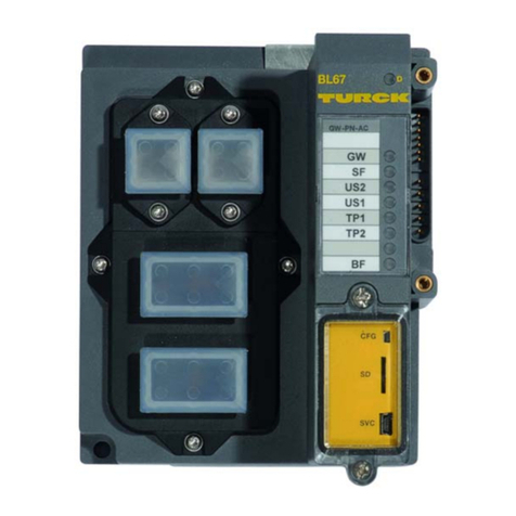
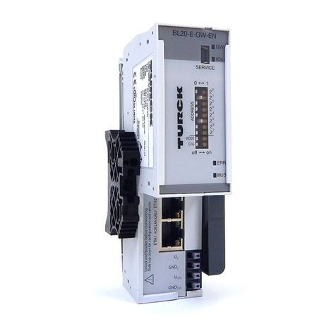
BL20-E-GW-EN

BL20-philosophy
D301173 0713 - BL20- Ethernet multiprotocol gateway2-4
Gateways with integrated power supply
All standard gateways BL20-GWBR-××× as well as the BL20-gateways for DPV1 and Ethernet (BL20-GW-
DPV1, BL20-GW-EN, BL20-GW-EN-IP, BL20-GW-EN-PN, BL20-PG-EN and BL20-PG-EN-IP) offer an
integrated power supply unit for feeding the gateway and the connected I/O modules.
It is not necessary to supply each individual module with a separate voltage.
Gateways without integrated power supply
2.2.2 Power distribution modules
The power supply for gateways and I/O modules is fed
to the power distribution modules; therefore, it is not necessary to supply each individual module with
a separate voltage.
Note
The gateways without integrated power supply unit need an additional power supply module (bus
refreshing module) which feeds the gateway an the connected I/O modules.
Figure 2-2:
Power distribu-
tion module

D301173 0713 - BL20- Ethernet multiprotocol gateway 2-5
BL20 components
2.2.3 Electronics modules (standard product line)
The standard electronics modules contain the I/O-functions of the BL20 modules (power distribution
modules, digital and analog input/output modules, and technology modules).
They are plugged onto the base modules and are not directly connected to the wiring
and can be plugged or pulled when the station is being commissioned or for maintenance purposes,
without having to disconnect the field wiring from the base modules.
Figure 2-3:
Electronics
module in slice
design (left) and
in Block design
(right)

BL20-philosophy
D301173 0713 - BL20- Ethernet multiprotocol gateway2-6
2.2.4 ECO electronics modules
New ECONOMY modules with a high signal density and exceptionally low channel price expand the
BL20 I/O bus terminal system.
Depending on type, up to 16 digital inputs and outputs can be connected on only 13 mm. This high
connection density considerably reduces the mounting width required for typical applications.
All advantages at a glance:
Space saving thanks to 16 channels on 13 mm/ 0.51 inch width
Cost saving thanks to electronics with integrated connection level
High signal density
Tool-less connection via "push-in" spring-type terminal technology for simple and fast mounting
Flexibility in combining them with standard I/O-modules in tension clamp technology, the
standard- and the ECO-gateways.
Simple assembly reduces error sources
Figure 2-4:
ECO I/O-module

D301173 0713 - BL20- Ethernet multiprotocol gateway 2-7
BL20 components
2.2.5 Base modules
The field wiring is connected to the base modules. These are constructed as terminals in block and slice
designs and are available in the following variations with either tension clamp or screw connections: 2-
/3-wire (2-channel), 4-wire (2-channel) and 4 x 2-/3-wire (4-channel).
Figure 2-5:
Base module
with tension
clamp connec-
tion
Figure 2-6:
Base module
with screw
connection
Figure 2-7:
Base module in
block design
This manual suits for next models
49
Table of contents
Other turck Gateway manuals

turck
turck GDP-NI Series User manual

turck
turck BL67-GW-EN Installation and user guide

turck
turck BL20 User manual

turck
turck BL20 User manual

turck
turck BL67-PG-EN-IP User manual

turck
turck BL67 User manual

turck
turck BL20 User manual

turck
turck BL20-E-GW-EC User manual

turck
turck BL20 User manual

turck
turck BL20-PG-EN-V3 User manual