FreshWater FW1000 User manual

Fresh Water Filter Co Ltd. Carlton House, Aylmer Road, Leytonstone, London E11 3AD.
Tel: +44 (0)20 8558 7495 Fax: +44 (0)20 8556 9270 Email: mail@freshwaterfilter.com www.freshwaterfilter.com
FW1000 & FW2000 Installation Guide & Technical Information (29/05/08) E & OE
FW1000 & FW2000 Installation Guide and Technical Information
Thank you for purchasing a FreshWater FW1000/FW2000 high quality drinking water pu-
rification system. It comprises a unique 7 stage ceramic cartridge, contained within
the stainless steel housing. Complete with full plumbing fittings and water dispensing
tap, it is designed for fast and easy installation using British patented speed fit connec-
tions.
The FW1000 system has a single, multi-technology cartridge contained within a single
housing. The FW2000 gives additional performance and a longer cartridge life. It com-
prises two stainless steel housings and two unique cartridges.
It is important that anyone installing a FreshWater®Filter system takes time to study
this guide as it contains essential information needed to ensure easy installation and
trouble-free use.
Follow the instructions and, after installation, your system will produce purified water
for drinking and preparing food at the touch of the special tap.
Keep the guide in a safe place. It will enable you to get the best performance from
your system now and in the future.
Section One Principal Components
Section Two Installation
Section Three Operating Instructions &
Maintenance
Section Four General Information
Section Five Parts List & Codes

Fresh Water Filter Co Ltd. Carlton House, Aylmer Road, Leytonstone, London E11 3AD.
Tel: +44 (0)20 8558 7495 Fax: +44 (0)20 8556 9270 Email: mail@freshwaterfilter.com www.freshwaterfilter.com
FW1000 & FW2000 Installation Guide & Technical Information (29/05/08) E & OE
FW1000 & FW2000 Installation Guide and Technical Information
Section 1
Principal Components
(Figs 1 and 2)
The first component in the system is the line-
piercing valve (1), which is easily connected to the
cold water supply line. (This is usually the supply
leading to the cold water tap in the kitchen.) The
line-piercing valve is connected by 3/8 inch flexi
pipe (food grade) (2) to the filter housing and
headwork’s (3), which contains the cartridge (4).
The 1/4” inch flexi pipe (6) is connected to the
Outlet tap.
The FW1000 comprises one cartridge (4) with seal
(5) in one housing. The FW2000 has two sumps (8,
9), the first of which contains the Type A car-
tridge. The second housing contains the Type B
cartridge (fig 2).
How the Components Function
1: Line piercing valve unit (LPV03)
The line piercing valve unit (Fig 3) consists of a
line-piercing valve together with an integral non-
return check valve. The unit is suitable for direct
installation on to standard copper cold water sup-
ply pipe of 15mm diameter. Other sizes are avail-
able on request. Please refer to the instructions
below for installation.
The valve can be used to control the water flow
rate and can be used to isolate the filter. The non-
return valve ensures that the direction of water
flow is always towards the filter, in accordance
with regulation designed to eliminate ’back-
siphoning’, an undesirable process in which fil-
tered material collected from the mains water by
the filter is released back into the water supply.
Figure 1
Figure 2
Figure 3

Fresh Water Filter Co Ltd. Carlton House, Aylmer Road, Leytonstone, London E11 3AD.
Tel: +44 (0)20 8558 7495 Fax: +44 (0)20 8556 9270 Email: mail@freshwaterfilter.com www.freshwaterfilter.com
FW1000 & FW2000 Installation Guide & Technical Information (29/05/08) E & OE
FW1000 & FW2000 Installation Guide and Technical Information
Filter Housing & Cartridges
The FW1000 cartridge (Fig 4) is a
multi-stage water treatment unit in
which the water enters the housing
and percolates from the outside
into the cartridge through the po-
rous ceramic. The first stage of
treatment is micro filtration
through the ceramic membrane.
This cleanses the water of sus-
pended particles. Because of its
superfine filtration characteristics -
the porous ceramic is too small for
bacteria to penetrate - it also per-
forms a further essential function.
It actually disinfects the water by
filtering out at least 99.99% of any
bacteria that might have entered
the water supply from the mains.
The water flows through the porous
ceramic cartridge and then passes
through a number of special water
treatment media, which serve to
improve the taste and act against a
whole range of chemical contami-
nants. The stainless steel filter
housing (the container for the car-
tridge) comprises a sump, which
can be unscrewed from the head-
works. (The headworks incorporate
water inlet and outlet connectors.)
The housing is rendered watertight
by the housing seal (Fig 5), that
fits inside the headworks.
Be careful with the screw thread
sections in the stainless steel hous-
ing. They can be razor sharp. Never
run your fingers over any sharp
edge. Remember stainless steel is
used for sharp surgical instruments!
To seal the cartridges into the
headwork’s within the stainless
steel housing, the upper spigot/
thread of the cartridge threads into
the head-works using the candle-
sealing washer (5). THIS SEAL IS
ESSENTIAL TO THE CORRECT WORK-
ING OF THE FILTER.
Develop the habit of checking that
it is in place before you screw on
the cartridge when you clean or
change the cartridge.
Also in the headwork’s you will see
the unique speed fit connectors.
The diagram (Fig 6), shows how
these work, you will see that it is
very simple to just push fit the
tube into the connectors but be
assured that this joint can with-
stand many times the pressure of
normal water supplies.
A Word of Caution!
The FW2000 system, which gives
additional performance and longer
cartridge life, comprises two
stainless steel housings and two
different types of cartridge (Fig 7).
Water flows through the first and
then through the second.
Filter cartridge Type A is similar to
the cartridge in the FW1000. It
consists of a first stage ceramic
membrane together with a series of
fine granular-form water treatment
media.
Filter cartridge Type B contains a
further series of different media
and is designed to operate only in
conjunction with cartridge Type A
to further remove water pollutants.
FW2000 System

Fresh Water Filter Co Ltd. Carlton House, Aylmer Road, Leytonstone, London E11 3AD.
Tel: +44 (0)20 8558 7495 Fax: +44 (0)20 8556 9270 Email: mail@freshwaterfilter.com www.freshwaterfilter.com
FW1000 & FW2000 Installation Guide & Technical Information (29/05/08) E & OE
FW1000 & FW2000 Installation Guide and Technical Information
Section 2
Installation
Before installation read these in-
structions carefully, then familiar-
ise yourself with the components,
determine where you are going to
install your system and plan the
installation.
STEP ONE
1: Unpacking
Handle with care and familiarise
yourself with the various compo-
nents after checking that they have
all been provided. (Refer to the
components lists included at the
end of this publication. Section 5)
STEP TWO
2: Drilling the Sink
Warning: If the sink is porcelain or
a similar vitreous material, do not
attempt to drill unless you have
sufficient technical ability and
equipment.
2.1: Vitreous Enamelled
or Porcelain Clad Cast
Iron Sinks
First, select the desired tap posi-
tion on a flat part of the sink or
draining board. To allow the tap to
pour into the sink, it should be
located no more than 100mm (4
inches) from the corner of the sink
bowl. Examine the underside of the
sink at that point to ensure that
you can get to it in order to con-
nect the tubing to the underside of
the tap assembly. Remember - you
will need to be able to get at the
underside of the sink at this point
with your hands and have sufficient
room to turn a spanner.
Before starting to drill the hole,
stick a small piece of insulating
tape over the area of vitreous
enamel or porcelain clad surface
you wish to drill. The tape will pre-
vent the drill bit from “walking”.
Using carbide drill bits, commence
drilling in the middle of the tape,
first using a 3.125mm (1/8 inch)
drill bit to make a pilot hole.
drill bits. After drilling the pilot
hole, make it progressively larger,
using in turn 6.25mm (1/4 inch),
9.375mm (3/8 inch) and finally
12.5mm (1/2 inch) drill bits.
By adopting this step-by-step
approach, using a sequence of
four drill bit sizes, the drill will
be prevented from “grabbing”
when it breaks through the sur-
face. This will avoid the risk of
damaging the sink, the drill and
the person using it.
As an additional precaution it is
also prudent to reduce pressure
on the drill immediately prior to
break through. Failure to reduce
pressure may result in causing
considerable damage to the sink,
particularly if its surface is vitre-
ous.
2.2: Stainless Steel
Sinks
Drill a 12.5mm (0.5 inch) hole in
the desired position using a high-
speed drill bit. Note the com-
ments in the section about first
piercing the sink surface in the
position you wish to drill.
2.3: Formica
Drill a 12.5mm (0.5 inch) hole
either using a carpenter’s drill or
a high speed bit.
STEP THREE
3: Mounting the Tap
Instructions for installing a Fresh-
Water Three Way Tap are pro-
vided separately in the tap’s box.
To install a FreshWater Mini Tap
please do the following:
Place the threaded portion of the
tap stem through the drilled hole
so that the lever is in a conven-
ient position for easy access
when you want to turn the tap
on.
Assemble in accordance with the
diagram) (Fig 8). Secure in place
with the nuts and washers pro-
vided. You may wish to use a
spanner on the flats of the tap to
hold it in the desired position. If
this is the case, be sure to place
a piece of cardboard between
the tap and the jaws of the span-
ner to avoid marking the polished
finish.
STEP FOUR
4: Connecting the Cold
Water Pipe Piercing Valve
Locate the main water stopcock
and make sure that it functions
correctly. The water supply should
be turned off at the mains until
installation is completed.
Find the copper cold water pipe
under the sink and select a suitable
section, which is straight and free
from surface coating such as paint.
Note: If you have other than a cop-
per pipe you should seek a
plumber’s advice on connecting the
filter. Iron and/or lead pipes need
special fitting.
Do not fit on the hot water line.
Please follow these simple
instructions to install your line-
piercing valve.
This valve is suitable for connection
to 15mm copper pipe supplying
domestic cold water.
1) To position valve outlet in
direction required.
a) Screw chrome locknut hand tight
against shoulder of valve.
b) Screw valve into saddle until
locknut contacts saddle.
c) Decide which way round kit is to
be fitted to pipe for positioning of
valve outlet.
Note: After water connection is
made valve can be unscrewed a
maximum of half a turn for final
positioning. (See instruction 7)

Fresh Water Filter Co Ltd. Carlton House, Aylmer Road, Leytonstone, London E11 3AD.
Tel: +44 (0)20 8558 7495 Fax: +44 (0)20 8556 9270 Email: mail@freshwaterfilter.com www.freshwaterfilter.com
FW1000 & FW2000 Installation Guide & Technical Information (29/05/08) E & OE
FW1000 & FW2000 Installation Guide and Technical Information
2) Remove saddle from backplate.
3) Screw backplate to wall. Use
packaging piece if necessary to
ensure pipe sits in groove in back-
plate. NB The backplate must be
firmly fixed to the wall in order to
avoid distortion of the copper pipe
and possible leakage when screw-
ing valve into saddle.
STEP FIVE
5: Positioning and Fitting
the Filter Unit.
The system is complete with a
bracket, which may be fitted to
any suitable surface. Although the
filter will operate in any position,
for ease of cleaning or replacing
the cartridges you will find it more
convenient if the filter unit is in-
stalled vertically with the bracket
and head at the top.
Position the filter so that you can
easily access it to unscrew the
housing from the head. A clear-
ance of 2 to 3 inches under the
housing is all that is needed.
Also, determine the best location
to permit connection to the (red)
inlet and (blue) outlet flexi pipe
tubing. When fitting the tubing
make certain that it does not form
tight bends and, if you cut the flexi
pipe, use a sharp knife and ensure
that the cut is straight.
Remember - the filter unit will be
much heavier when it is filled with
water. It is therefore important
that the bracket is securely
mounted, in a manner, which is
sufficiently strong, and robust to
prevent it coming loose when the
stainless steel housing is removed
and replaced when you wish to
clean the filter cartridges).
Care is needed to select a good
position. Weak laminates can easily
be damaged. ‘Key hole slots’ for
the fixing screws have been made
in the bracket to enable the com-
plete system to be removed from
its fixed position for regular main-
tenance etc.
After determining the location of
the stainless steel filter unit, on
the surface you are going to fix it
to, use a pencil to mark the screw
positions which correspond with
the screw holes on the back of the
brackets which carry the head-
work’s and filter housings).
Bracket securing screws are in-
cluded with the system. If you are
fixing to a masonry wall, first drill
holes using a suitable drill bit and
insert plastic screw retainer plugs
(rawl plugs for example).
STEP SIX
6: Connecting Up
Connect the red flexi pipe tubing
to the INLET side of the filter hous-
ing headwork’s (Fig 5) and into the
speed fit connecter on the line-
piercing valve (CI321214S). Push
the tubing well into the speed fit
connector. When it is fully in place
it will not leak and can only be
released by pressing in the collet at
the same time as withdrawing the
tubing. Next push the second run of
flexi pipe - the blue tubing - into
the OUTLET side of the filter hous-
ing headworks.
The direction of flow is from INLET
to OUTLET. (As per arrow marked
on the head-works)
Caution! The wrong direction of
water flow will damage the car-
tridge.
STEP SEVEN
7: Testing for leaks
Make sure that all the speed fit
push-in joints are securely posi-
tioned by pushing the flexi pipe
firmly. Ensure that the cartridge
housing is screwed tightly onto the
headworks. Ensure that the whole
system is connected correctly and
all joints are tight and firmly
attached.
With the line piercing valve still in
the closed (clockwise) position,
turn on the mains water supply and
check that the line piercing valve is
tightly connected and not leaking.
Now slowly open the line piercing
valve tap and check the entire in-
stallation for leaks. Check very
carefully.
Once you are happy that there are
no leaks, WITH NO CARTRIDGES
INSTALLED set the FRESHWATER
FILTER®outlet tap to continuous
flow mode and flush out the line
for a few minutes. Again, check
for leaks whilst the water is on
continuous flow.
STEP EIGHT
8: Inserting the
Cartridges
Turn off the water by closing the
line piercing valve tap and relieve
the pressure by turning on the long
reach fountain tap until the flow
stops.
Unscrew the housing(s) from the
headworks. In the case of the
FW2000 make sure that the housing
for the Type A cartridge is kept
separate from the Type B car-
tridge.
Remove any protective wrapping
from the cartridges. CHECK THAT
THE INTERNAL SEALING RING(S)
INSIDE THE HEAD AND THE ‘O’RING
WASHER(S) ON THE STAINLESS
STEEL HOUSING(S) ARE CORRECTLY
LOCATED before screwing the hous-
ings tightly onto the headwork’s.
STEP NINE
9: Conditioning
Before using your FRESH WATER
FILTER, first fill the system with
water.
This is done as follows:
a) Turn on the water flow at the
outlet tap until a continuous flow
of water emerges; - run the whole
system for several minutes until
the water tastes good. For the first
few seconds you may observe a
black water condition, this is per-
fectly normal - ignore it - and con-
tinue to flush until the water runs
clean.

Fresh Water Filter Co Ltd. Carlton House, Aylmer Road, Leytonstone, London E11 3AD.
Tel: +44 (0)20 8558 7495 Fax: +44 (0)20 8556 9270 Email: mail@freshwaterfilter.com www.freshwaterfilter.com
FW1000 & FW2000 Installation Guide & Technical Information (29/05/08) E & OE
FW1000 & FW2000 Installation Guide and Technical Information
b) After carrying out the condition-
ing procedure, turn off the tap so
the whole unit is fully under mains
water pressure and check the unit
very carefully for leaks. It is impor-
tant to check again after a few
hours in case there is a very slow
and small leak. A small saucer un-
der the filter will catch any drips,
and will enable you to confirm that
all is correct.
Section 3
Operating Instructions
1: Routine use
Hold the tap lever down to turn on
the water flow. Run the water for a
few seconds before use.
The water flow rate should be kept
at around 1.5 litres per minute at 5
bar pressure for optimum perform-
ance (about 24 seconds to fill a
pint bottle). The flow may be re-
duced by partially closing the con-
trol valve on the line piercing as-
sembly.
During use, unwanted particulate
material will collect on the outside
surface of the ceramic membrane
and this will reduce the water flow
rate. If the line-piercing valve is
fully open and the flow rate be-
comes unacceptably low, this nor-
mally indicates that the filter
needs replacing.
Under normal conditions, after
3000 litres (over 800 gallons) of
water have passed through your
FW1000 or six months has passed,
whichever comes first.
With the FW2000 both cartridges
should be replaced after 6000 litres
(over 1000 gallons) have passed
through it, or every 12 months,
whichever comes first.
Whenever a cartridge is replaced or
the filter housing opened for in-
spection, please check carefully to
ensure that there are no leaks.
From time to time, should the ‘O’
seal become brittle, or break, or
cause a leak it will need replacing.
‘O’ seals should be wiped with
white petroleum jelly (Vaseline) to
help lubrication.
Section 4
General information
1: Useful tips
With just the minimum of mainte-
nance and attention your
FRESHWATER FILTER high quality
water purification system will give
you many years of excellent ser-
vice. The following tips may be
useful:
A.) NEVER install the filter where
the water can freeze, as this will
break the ceramic and may damage
the seals.
B.) Install the filter only on the
COLD water line, never on the hot
water line.
C.) Check the filter regularly for
water leaks as these may indicate
faulty installation or maintenance.
D.) Always use white petroleum
jelly (Vaseline) on the ‘O’ seals to
help lubricate them and enable the
housing to be opened more easily.
E.) Never run your fingers over the
stainless steel threads or edges of
the filter - they are razor sharp.
F.) Read this user guide carefully
and keep it - and the set of spares -
in a safe place.
G.) For optimum performance
clean and replace the filters regu-
larly in accordance with the in-
structions.
2: Fault Finding
If you have any difficulty in install-
ing the filter on maintaining the
filter you may find the following
useful:
2.1: No Water
A.) Check that the main stopcock is
open and that the mains water is
still on.
B.) Check that the line-piercing
valve is open. (Turn anti clock-
wise.)
C.) Check that the dispensing tap is
open.
D.) Check that all the pipes are
connected correctly.
E.) Check direction of water flow
2.2: Low Water Flow
A.) Check that you have removed
all the wrapping from a new filter
cartridge.
B.) Low water pressure. During
periods of high water demand the
pressure may fall and so will the
water flow from the filter. Running
a bath, shower or appliance con-
nected to same line on which your
FRESHWATER FILTER®system is
connected may starve the unit of
water.
C.) During use, low water flow may
be an indication that the filter is
becoming blocked as it collects the
unwanted debris and pollutants
from the water.
D) Check that the line-piercing
valve is fully opened, or if there is
low flow at the time of installation
check that the line piercing valve
instructions were carried out cor-
rectly and that the water line has
been pierced fully. (Close the line
piercing valve fully and then open
it up again).
E) The filter system needs a mini-
mum pressure of 2 Bar
(approximately 29 psi) to work. As
a general rule, the higher the pres-
sure generally the greater the wa-
ter flow will be. If the pressure is
inadequate a pump may be
needed, and for this you should
contact the manufacturer or a
plumber.

Fresh Water Filter Co Ltd. Carlton House, Aylmer Road, Leytonstone, London E11 3AD.
Tel: +44 (0)20 8558 7495 Fax: +44 (0)20 8556 9270 Email: mail@freshwaterfilter.com www.freshwaterfilter.com
FW1000 & FW2000 Installation Guide & Technical Information (29/05/08) E & OE
FW1000 & FW2000 Installation Guide and Technical Information
2.3: High Water Flow
If the water flow has excessive
force, this will lead not only to
splashing at the tap but also to
lower performance from the filter.
Reduce the flow rate to the mini-
mum acceptable by turning the line
piercing valve handle in the clock-
wise direction. For optimum per-
formance we suggest a flow rate of
1.5 litres per minute or less.
2.4: Water Appearance
WHITE water. When a fresh ce-
ramic cartridge is installed or after
cleaning, the water may appear
milky or white for a while. It is
quite harmless and will soon clear.
White water is due to micro bub-
bles of air. On standing, the water
will become clear as the bubbles
move upwards. Water in some
areas of the country is more prone
to this than others.
BLACK water. On setting up your
system after cleaning or if it is dis-
turbed for any reason, very fine
black particles may occur in the
water. Again this is quite normal
and the particles are harmless car-
bon. Flushing the system for a few
minutes by turning the tap on and
off rapidly several times will help
to clear this.
COLOURED water (often RED).
Water in some areas may be high in
dissolved iron and this can pass
through the filter. When the water
is left to stand, dissolved iron gives
a red or brown colour as the iron
oxidises (rusts). In very severe
cases you should contact the manu-
facturer for specialist advice.
Ordinary particulate rust in the
water will be removed by the
system.
2.5: Water Taste
To the palates of most people, fil-
tered and treated water tastes so
much better than unfiltered water.
There are also some people who
cannot detect any change. Others
find that the treated water tastes
“different”, but they will soon be-
come accustomed to the taste of
the purer water.
A major factor affecting taste may
be the natural composition in a
particular area. There can be con-
siderable local differences in the
mineral content of the water for
example. The ‘natural’ taste of an
area’s water is often masked by the
presence of chlorine used in the
treatment process. If the chlorine
taste consistently reappears, the
cartridge should be replaced.
If, after prolonged standing or dur-
ing infrequent use any strong ob-
jectionable taste occurs, flush the
system by running water for 5 min-
utes and if the taste persists carry
out the sanitising process (see Sec-
tion Three, Steps 2,7).
Note that during the disinfection
process chlorine will be generated
and this will taint the water. Flush
the system adequately to remove
this.
2.6: Water Leaks
Your system has been individually
pressure tested before leaving the
factory. In the unlikely event of a
fault, small leaks sometimes do
occur as a result of incorrect as-
sembly or abuse. The following tips
may be helpful:
A.) Depending on the positioning
of the filter and the temperature
of the incoming water and air, con-
densation on the outside of the
filter housing may occur, resulting
in a frosted appearance of fine
water droplets on the stainless
steel surface. This does not of
course mean that there is a leak in
the system. The remedy is to ei-
ther insulate the area around the
filter, or reposition it.
B.) Always ensure that the ‘O’
seals and the areas in which they
are located are clean. Any small
piece of debris on the seal of the
surrounding area could cause a
small leak. Apply a smear of petro-
leum jelly to the seal.
C.) Always ensure that the filter
housing is screwed fully onto the
headworks. This is essential both
for the internal seal and the hous-
ing seal.
D.) In the event of a leak carefully
examine its source. Water from a
leak may run along the pipe work -
it may drip, or collect, some dis-
tance from the actual position of
the leak.
E.) When the leak is found, if it is
an ‘O’ seal first clean the seal and
the surrounding area and reassem-
ble with a smear of silicone grease
or white petroleum jelly. If this
does not solve the problem fit a
replacement seal.
F.) Leaks occurring at the line
piercing valve may mean that the
unit has not been fully clamped
onto the water line - please adhere
to the instructions given in Section
Two, Step 4.
G.) Leaks at the speed fit connec-
tors are usually due to the tubing
not being pushed fully into the fit-
ting. Remove the tubing, cut off
an inch of tubing with a sharp knife
and reinsert into the speed fit con-
nector. Ensure that the speed fit
collet is in position. When fitted
correctly, the tube should not pull
out of the fitting (unless the collet
is pushed in at the same time to
release the tubing).
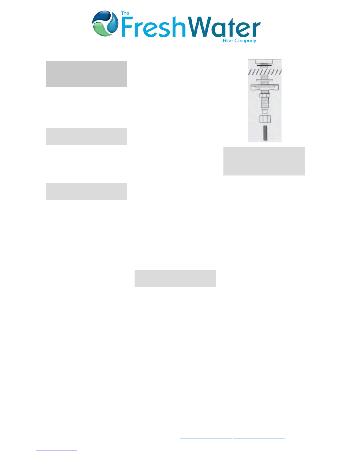
H.) Leaks from the bottom of the
dispensing tap could be due to in-
correct installation. Make sure that
the components are fitted correctly
and that the compression nuts are
fully tightened. Be certain to check
the small white washer seal in the
adapter.

Fresh Water Filter Co Ltd. Carlton House, Aylmer Road, Leytonstone, London E11 3AD.
Tel: +44 (0)20 8558 7495 Fax: +44 (0)20 8556 9270 Email: mail@freshwaterfilter.com www.freshwaterfilter.com
FW1000 & FW2000 Installation Guide & Technical Information (29/05/08) E & OE
FW1000 & FW2000 Installation Guide and Technical Information
I) If there is a leak from the body
of the tap, check that the tap out-
let arm is pushed down firmly. Two
‘O’ rings are fitted to the tap out-
let spout - ensure they are still in
position.
A drip from the tap can be cured by
removing the outlet arm. First,
slip off the black lever handle. Un-
der this will be found a small ‘T’
bar. Give the ‘T’ bar a half turn
anticlockwise and reassemble.
Note The above should be carried
out with the water turned off at
the line-piercing valve.
2.7: Sanitising the System
(A) Place 3 ‘Puritabs’ disinfecting
tablets in each housing with the
cartridge(s)
(B) Fill the system with water by
opening the outlet tap for 10
seconds ignore the colour of the
water
(C) Turn off the water at the tap
and allow to stand for 20 minutes.
(D) Now run the system for a few
minutes until the water tastes pal-
atable.
2.8: Going on Holiday
If you go away for a holiday or are
away for a few days, it is recom-
mended practise to turn off the
household mains water, whether or
not you have a FRESHWATER FILTER
system. When you return, run the
water through the system for a few
minutes so that the water you drink
is freshly filtered.
Section 5
FW1000
FW2000
Part No. Diagram
No.
Component/Parts (s) Quantity -
FW1000
Quantity
-
FW2000
MS 3 Stainless steel housing head
sump and seal
Part Nos (F1012A, F1011A
and FW1007B)
1 2
FW1001 Stainless Steel Bracket
FW1000
1
FW1002/
2
3/8" insert plastic 2 2
FW2001 Stainless Steel Bracket
FW2000
1
FW1008 Bracket screws 48
FW1007B MS Seal Washer 1 1
FW1009 Wall Mounting Screws 2 3
TB-P-1/4 6 1/4 inch flexi pipe tubing 1 1
TB-PR-
3/8
2 3/8 Inch Flexi pipe tubing 1 1
LPV03 1 Opella line piercing valve
for 15mm pipe
1 1
CI321214
S
1/2" FI to 3/8" JG Adaptor 1 1
GSP-09/B 5 Candle Sealing Washer 1 2
1000X-
25-SM
4 FW1000 cartridge (Inc seal
GSP09/B)
1
2000X-
25-SM
FW2000 cartridges
Type A & B (inc seal
GSP09/B x 2)
1
This manual suits for next models
1
Table of contents
Other FreshWater Water Filtration System manuals
Popular Water Filtration System manuals by other brands

JRC
JRC NSVA276 manual

SteriPEN
SteriPEN Classic 3 user manual

STODDART
STODDART SPWA.PCRO1 Specification, installation and operation manual

BWT
BWT bestaqua24 HQ Fitting and operating instructions

3P Technik
3P Technik 3P Rustico instruction sheet

Savio
Savio Livingponds F070 Operating Manual & Specifications