Frick RXB PLUS Owner's manual

ROTARY SCREW COMPRESSOR UNITS
WITH
MICROPROCESSOR CONTROL
ALL REFRIGERANTS
THIS MANUAL CONTAINS RIGGING, ASSEMBLY, START-UP, AND
MAINTENANCE INSTRUCTIONS. READTHOROUGHLY BEFORE BE-
GINNING INSTALLATION. FAILURE TO FOLLOW THESE INSTRUC-
TIONS COULD RESULT IN DAMAGE OR IMPROPER OPERATION
OF THE UNIT.
Form S70-101 IOM (JAN 2000)
INSTALLATION - OPERATION - MAINTENANCE
File: SERVICE MANUAL - Section 70
Replaces: S70-101 IOM (APR 96)
Dist: 3, 3a, 3b, 3c

RXB PLUS ROTARY SCREW COMPRESSOR UNITS
INSTALLATION - OPERATION - MAINTENANCE
S70-101 IOM
Page 2
GENERAL INFORMATION
Preface .............................................................................. 3
Design Limitations ............................................................. 3
Job Inspection ................................................................... 3
Transit Damage Claims ..................................................... 3
Compressor/Unit Identification .......................................... 3
INSTALLATION
Foundation......................................................................... 4
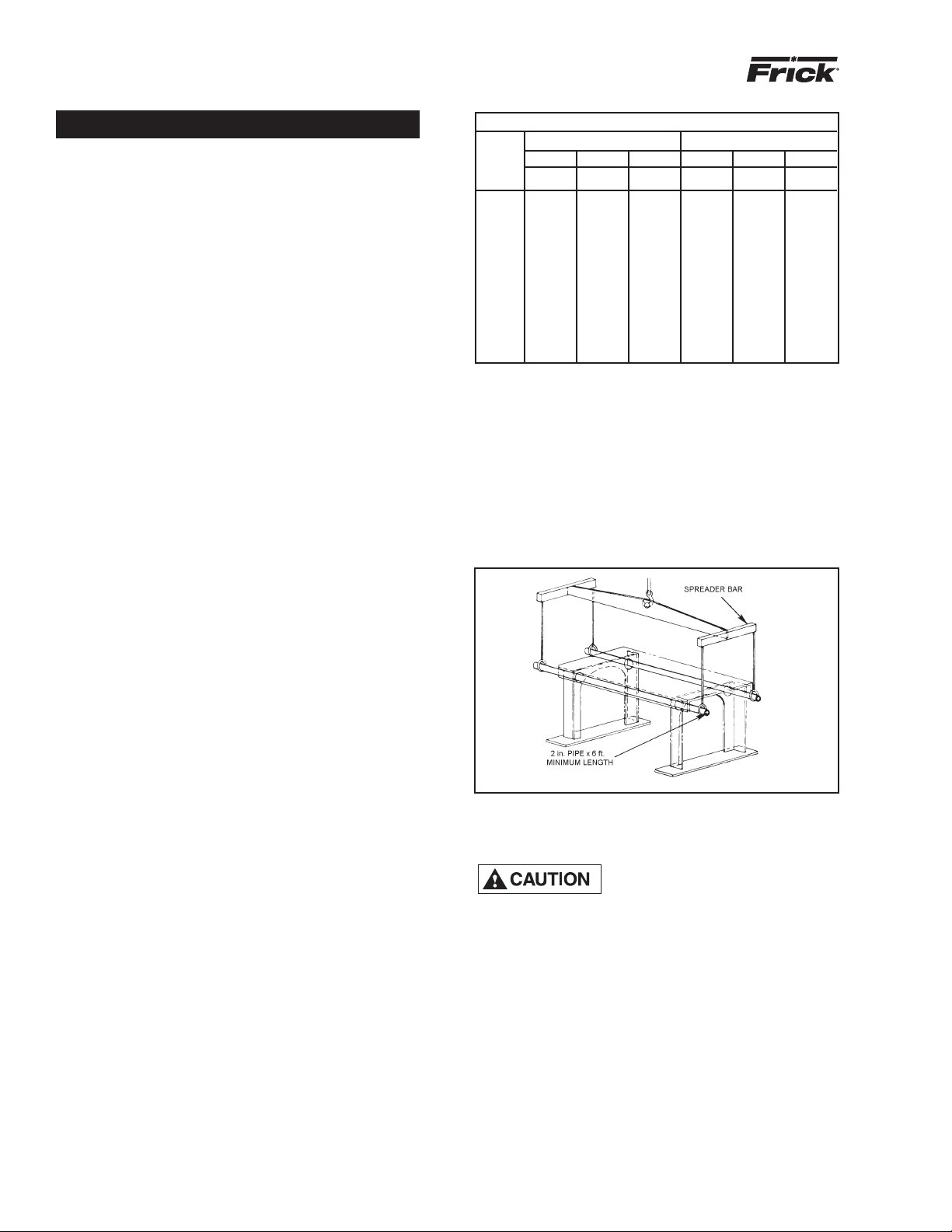
Handling and Moving......................................................... 4
Skid Removal .................................................................... 5
Motor Mounting.................................................................. 5
Compressor/Motor Coupling Installation ........................... 5
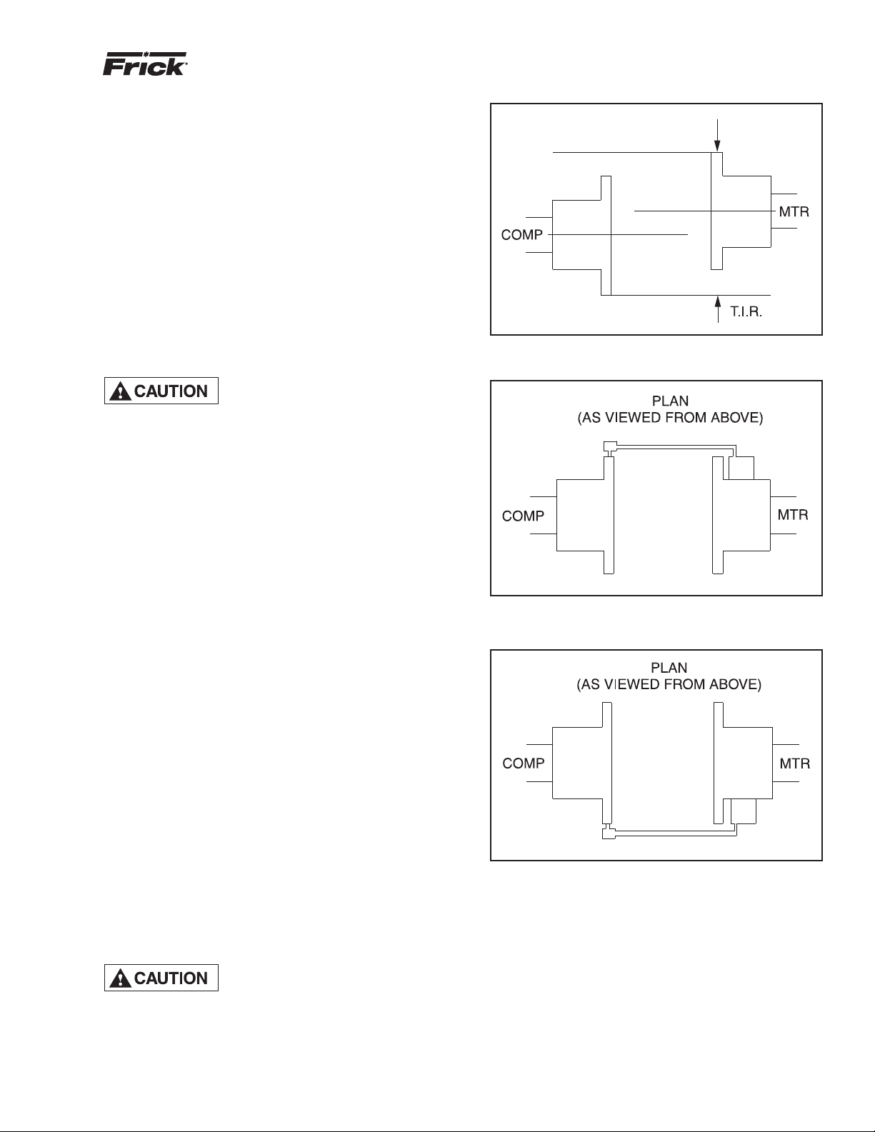
Coupling Alignment Procedure.......................................... 6
Hot Alignment of Compressor/Motor ................................. 8
Checking Motor/Compressor Rotation .............................. 8
Holding Charge and Storage............................................. 8
Compressor Oil.................................................................. 8
Oil Charge ......................................................................... 8
Oil Heater .......................................................................... 8
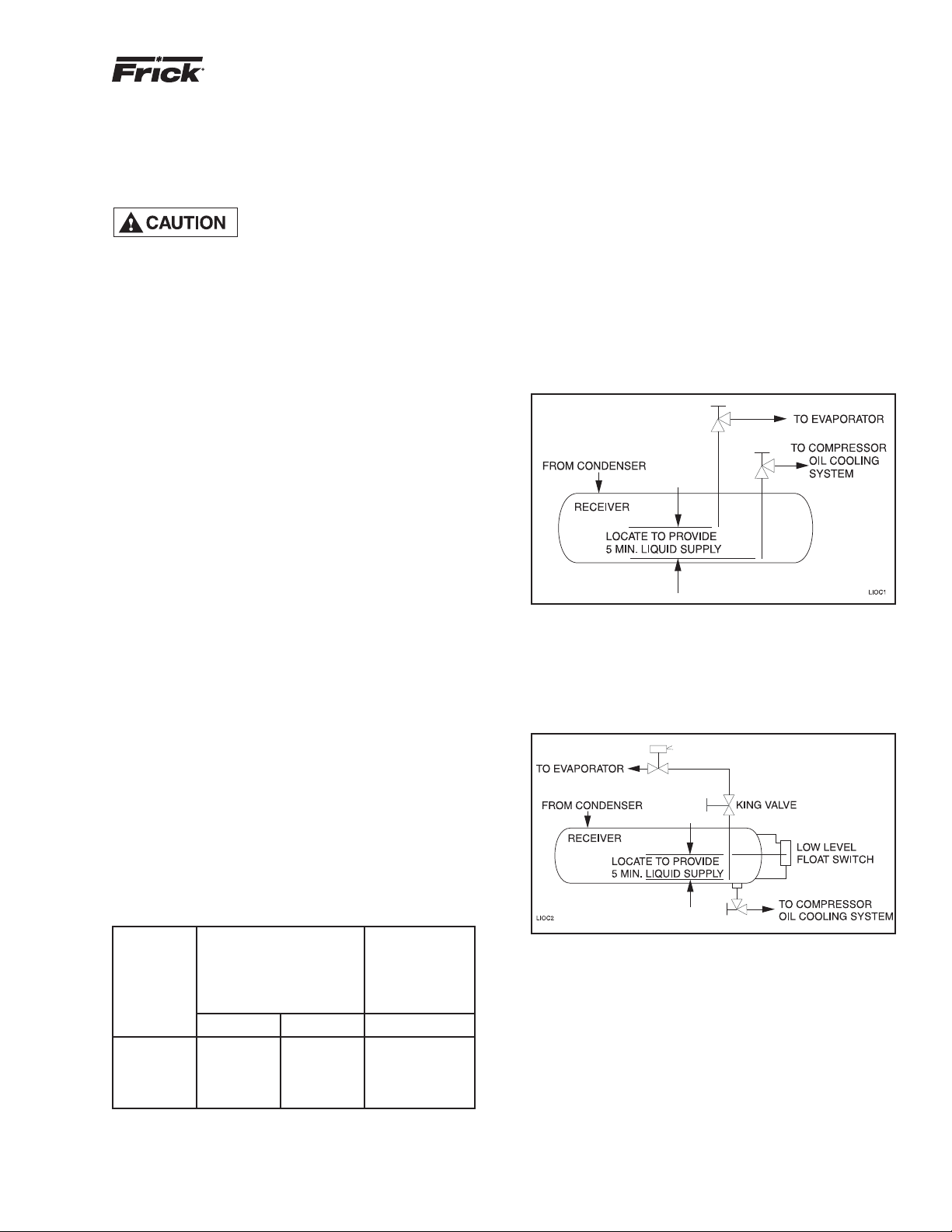
Liquid Injection Oil Cooling................................................ 9
Dual Dip Tube Method ....................................................... 9
Level Control Method......................................................... 9
Water-Cooled Oil Cooling................................................ 10
Thermosyphon Oil Cooling.............................................. 10
Economizer - High Stage................................................. 12
Electrical.......................................................................... 13
Motor Starter Package..................................................... 13
Current Transformers (CT) Ratios ................................... 14
Minimum Burden Ratings ................................................ 14
Battery Backup ................................................................ 14
OPERATION
General Information......................................................... 15
Microprocessor Control Panel ......................................... 15
Keys and Key Functions .................................................. 16
To Change The Adjustable Setpoints .............................. 18
How To Determine Adjustable Setpoints ......................... 18
Temperature-Pressure Control Program ......................... 22
Lead-Lag (Option) ........................................................... 24
Communications Troubleshooting.................................... 24
How The Microprocessor Works - Summary ................... 25
Multiple Compressor Sequencing.................................... 26
Microprocessor Telecommunications............................... 27
Communications Protocol Specifications ........................ 27
RXB Compressor............................................................. 30
Compressor Lubrication System ..................................... 30
Full-Lube Oil System ....................................................... 30
Compressor Oil Separation System ................................ 30
Compressor Hydraulic System ....................................... 31
Compressor Oil Cooling Systems.................................... 32
Single-Port Liquid Injection.............................................. 32
Dual-Port Liquid Injection ................................................ 33
Liquid Injection Adjustment Procedure............................ 33
TABLE OF CONTENTS
Prestart Checklist ............................................................ 34
Initial Start-up Procedure................................................. 35
Normal Start-up Procedure ............................................. 35
Restarting Unit After Power Failure ................................. 35
MAINTENANCE
Normal Maintenance Operations..................................... 36
Compressor Shutdown and Start-up ............................... 36
General Instructions For Replacing
Compressor Unit Components..................................... 36
Suction Check Valve Bypass Valve.................................. 36
Oil Filter, Single ............................................................... 36
Oil Filter, Dual.................................................................. 37
Strainer, Oil Return.......................................................... 37
Strainer, Oil Pump (Optional)........................................... 37
Strainer, Liquid Injection .................................................. 37
Coalescer Filter Element ................................................. 38
Changing Oil.................................................................... 38
Recommended Maintenance Program............................ 38
Vibration Analysis ............................................................ 39
Oil Quality and Analysis................................................... 39
Motor Bearings ................................................................ 39
Operating Log.................................................................. 39
Maintenance Schedule.................................................... 40
Troubleshooting Guide..................................................... 41
Abnormal Operation Analysis and Correction ................. 41
Troubleshooting The Microprocessor............................... 42
EPROM Memory I/C Chip Replacement ......................... 45
SBC Board Replacement ................................................ 45
Microprocessor Display Replacement ............................. 45
Output Fuse Replacement............................................... 45
Pressure Transducers - Testing ....................................... 45
Pressure Transducer Conversion Data............................ 45
Pressure Transducers - Replacement ............................. 46
Volumizer Potentiometer - Replace/Adjust ...................... 47
Temperature/Pressure Adjustment .................................. 47
Bare Compressor Mounting............................................. 47
Troubleshooting The RXB PLUS:
Compressor ................................................................. 48
Oil Separator System................................................... 48
Hydraulic System ......................................................... 48
Full-Time Pump Systems............................................. 49
Liquid Injection Oil Cooling .......................................... 49
Thermal Expansion Valves .............................................. 50
Temperature Control Valve .............................................. 51
Wiring Diagrams .............................................................. 52
P and I Diagrams............................................................. 58
PROPER INSTALLATION OF ELECTRONIC
EQUIPMENT................................................................ 60
OPERATING LOG........................................................... 63

RXB PLUS ROTARY SCREW COMPRESSOR UNITS
INSTALLATION - OPERATION - MAINTENANCE
S70-101 IOM
Page 3
PREFACE
This manual has been prepared to acquaint the owner and
serviceman with the INSTALLATION, OPERATION, and
MAINTENANCE procedures as recommended by Frick for
RXB PLUS Rotary Screw Compressor Units.
It is most important that these units be properly applied to an
adequately controlled refrigeration system. Your authorized
Frick representative should be consulted for his expert guid-
ance in this determination.
Proper performance and continued satisfaction with these
units is dependent upon:
CORRECT INSTALLATION
PROPER OPERATION
REGULAR, SYSTEMATIC MAINTENANCE
To ensure correct installation and application, the equipment
must be properly selected and connected to a properly de-
signed and installed system. The Engineering plans, piping
layouts, etc. must be detailed in accordance with the best
practices and local codes, such as those outlined in ASHRAE
literature.
A refrigeration compressor is a VAPOR PUMP. To be certain
that it is not being subjected to liquid refrigerant carryover, it
is necessary that refrigerant controls are carefully selected
and in good operating condition; the piping is properly sized
and traps, if necessary, are correctly arranged; the suction
line has an accumulator or slugging protection; that load
surges are known and provisions made for control; operating
cycles and defrosting periods are reasonable; and that high
side condensers are sized within system and compressor
design limits.
It is recommended that the entering vapor temperature to the
compressor be superheated to 10OF above the refrigerant
saturation temperature. This ensures that all refrigerant at
the compressor suction is in the vapor state.
DESIGN LIMITATIONS
The compressor units are designed for operation within
the pressure and temperature limits as shown in Frick Pub.
E70-100 SED.
JOB INSPECTION
Immediately upon arrival examine all crates, boxes and
exposed compressor and component surfaces for damage.
Unpack all items and check against shipping lists for any
possible shortage. Examine all items for damage in transit.
TRANSIT DAMAGE CLAIMS
All claims must be made by consignee. This is an ICC re-
quirement. Request immediate inspection by the agent of the
carrier and be sure the proper claim forms are executed.
Report damage or shortage claims immediately to Frick ,
Sales Administration Department, in Waynesboro, PA.
COMPRESSOR and UNIT IDENTIFICATION
Each compressor unit has 2 identification data plates. The
compressor data plate, containing compressor model
and serial number, is mounted on the compressor body.
The unit data plate, containing unit model, serial number,
and Frick sales order number, is mounted on the side of the
motor base.
NOTE: When inquiring about the compressor or unit,
or ordering repair parts, provide the MODEL, SERIAL,
and FRICK SALES ORDER NUMBERS from these data
plates.
UNIT DATA PLATE
COMPRESSOR DATA PLATE

RXB PLUS ROTARY SCREW COMPRESSOR UNITS
INSTALLATION
S70-101 IOM
Page 4
Installation
FOUNDATION
Each RXB PLUS Rotary Screw Compressor Unit is shipped
mounted on a wood skid which must be removed prior to unit
installation. CAUTION: Allow space for servicing both ends
of the unit. A minimum of 24 inches is recommended.
The first requirement of the compressor foundation is that it
must be able to support the weight of the compressor pack-
age including coolers, oil, and refrigerant charge. Screw
compressors are capable of converting large quantities of
shaft power into gas compression in a relatively small space
and a mass is required to effectively dampen these relatively
high frequency vibrations.
Firmly anchoring the compressor package to a suitable
foundation by proper application of grout and elimination of
piping stress imposed on the compressor is the best insur-
ance for a trouble free installation. Use only the certified
general arrangement drawings from Frick to determine the
mounting foot locations and to allow for recommended clear-
ances around the unit for ease of operation and servicing.
Foundations must be in compliance with local building codes
and materials should be of industrial quality.
The floor should be a minimum of 6 inches of reinforced
concrete and housekeeping pads are recommended. Anchor
bolts are required to firmly tie the unit to the floor. Once the
unit is rigged into place (See HANDLING and MOVING), the
feet must then be shimmed in order to level the unit. The
shims should be placed to position the feet roughly one inch
above the housekeeping pad to allow room for grouting. An
expansion-type epoxy grout must be worked under all areas
of the base with no voids and be allowed to settle with a slight
outward slope so oil and water can run off of the base.
When installing on a steel base, the following guidelines
should be implemented to properly design the system base:
1. Use I-beams in the skid where the screw compressor will
be attached to the system base. They should run parallel to
the package feet and support the feet for their full length.
2. The compressor unit feet should be continuously welded to
the system base at all points of contact, or bolted.
3. The compressor unit should not be mounted on vibration
isolators in order to hold down package vibration levels.
4. The customer’s foundation for the system base should fully
support the system base under all areas, but most certainly
under the I-beams that support the compressor package.
When installing on the upper floors of buildings, extra precau-
tions should be taken to prevent normal package vibration
from being transferred to the building structure. It may be
necessary to use rubber or spring isolators, or a combination
of both, to prevent the transmission of compressor vibration
directly to the structure. However, this may increase package
vibration levels because the compressor is not in contact with
any damping mass. The mounting and support of suction
and discharge lines is also very important. Rubber or spring
pipe supports may be required to avoid exciting the building
structure at any pipe supports close to the compressor pack-
age. It is best to employ a vibration expert in the design of
a proper mounting arrangement.
In any screw compressor installation, suction and discharge lines
should be supported in pipe hangers (preferably within 2 ft. of
vertical pipe run) so that the lines won’t move if disconnected
from the compressor. See table for Allowable Flange Loads.
HANDLING AND MOVING
THIS UNIT MAY BE TOP HEAVY.
USE CARE WHILE HANDLING.
Spreader bars should be used on
both the length and width of the package to prevent
bending of oil lines and damage to the package.
The unit can be moved with rigging, using a crane or forklift.
The recommended method is to insert lengths of 2” pipe
through the lifting holes in the vertical supports (see FIG. 1).
Alternatively, hooks may be used in rigging, inserting them
in the lifting holes (see FIG. 2).
Use CAUTION in locating the lifting ring. If no motor is
mounted, the lifting ring should be moved off center to
the compressor side of the unit because 60 percent of the
weight is toward the compressor end. If a motor is mounted,
appropriate adjustment in the lifting point should be made
to compensate for motor weight. Adjustment of the lifting
point must also be made for any additions to the standard
package, such as an external oil cooler, etc., as the center
of balance will be affected.
FIG. 1 - RECOMMENDED LIFTING METHOD
A licensed architect should be consulted to determine the
proper foundation requirements for any large engine or
turbine drive.
When applying screw compressors at high pressures, the
customer must be prepared for package vibration and noise
higher than the values predicted for normal refrigeration duty.
Proper foundations and proper installation methods are vital;
and even then, sound attenuation or noise curtains may be
required to reduce noise to desired levels.
For more detailed information on Screw Compressor Founda-
tions, please request Frick publication S70-210 IB.
ALLOWABLE FLANGE LOADS
NOZ. MOMENTS (ft-lbf) LOAD (lbf)
SIZE AXIAL VERT. LAT. AXIAL VERT. LAT.
NPS MRM
C ML P VC VL
1 25 25 25 50 50 50
1.25 25 25 25 50 50 50
1.5 50 40 40 100 75 75
2 100 70 70 150 125 125
3 250 175 175 225 250 250
4 400 200 200 300 400 400
5 425 400 400 400 450 450
6 1000 750 750 650 650 650
8 1500 1000 1000 1500 900 900
10 1500 1200 1200 1500 1200 1200
12 1500 1500 1500 1500 1500 1500
14 2000 1800 1800 1700 2000 2000

RXB PLUS ROTARY SCREW COMPRESSOR UNITS
INSTALLATION
S70-101 IOM
Page 5
FIG. 2 - ALTERNATIVE LIFTING METHOD
The unit can be moved with a forklift by forking under the skid,
or it can be skidded into place with pinch bars by pushing
against the skid. NEVER MOVE THE UNIT BY PUSHING
OR FORKING AGAINSTTHE SEPARATOR SHELL OR ITS
MOUNTING SUPPORTS.
SKID REMOVAL
If the unit is rigged into place the skid can be removed
by taking off the nuts and bolts that are fastening the unit
mounting supports to the skid before lowering the unit onto
the mounting surface.
If the unit is skidded into place, remove the cross members
from the skid and remove the nuts anchoring the unit to the
skid. Using a 5-ton jack under the separator, raise the unit
at the compressor end until it clears the two mounting bolts.
Spread the skid to clear the unit mounting support, then lower
the unit to the surface. Repeat procedure on opposite end.
MOTOR MOUNTING
The following procedure is required only when the motor is
mounted at the job site.
1. Thoroughly clean the motor feet and mounting pads of
grease, burrs, and other foreign matter to ensure firm seat-
ing of the motor.
2. Attach the motor to the base using the bolts and motor-
raising blocks, if required. Bolt snugly through the base.
3. Weld the four kick bolts into place so that they are posi-
tioned to allow movement of the motor feet.
4. Now that the motor has been set, check that the shafts
are properly spaced for the coupling being used. Refer to
the coupling data table for the applicable dimension.
COMPRESSOR/MOTOR COUPLING
INSTALLATION
RXB PLUS units are arranged for direct motor drive and
require a flexible drive coupling to connect the compressor
to the motor. Before installing, perform the following:
1. Inspect the shaft of the motor and compressor to ensure
that no nicks, grease, or foreign matter is present.
2. Inspect the bores in the coupling hubs to make sure that
they are free of burrs, dirt, and grit.
3. Check that the keys fit the hubs and shafts properly.
CH COUPLING – The T.B.Woods Elastomeric CH Coupling
is used in most applications. It consists of two drive hubs
and a loose, gear-type Hytrel Drive Spacer. The split hub is
clamped to the shaft by tightening the clamp screws.Torque
is transmitted from the motor through the elastomeric gear
which floats freely between the hubs. Install as follows:
IT IS MANDATORYTHATTHE COU-
PLING CENTER BE REMOVED
AND THE DIRECTION OF MOTOR
ROTATION BE CONFIRMED BEFORE RUNNING THE
COMPRESSOR. Proper rotation of the compressor shaft
is clockwise looking at the end of the compressor shaft.
FAILURE TO FOLLOW THIS STEP COULD RESULT IN
BACKWARD COMPRESSOR ROTATION WHICH CAN
CAUSE COMPRESSOR FAILURE OR EXPLOSION OF
THE SUCTION HOUSING.
1. Slide one hub onto each shaft as far as possible. It may
be necessary to use a screwdriver as a wedge in the slot to
open the bore before the hubs will slide onto the shafts.
2. Hold the elastomeric gear between the hubs and slide both
hubs onto the gear to fully engage the mating teeth. Make
sure that the keys on the compressor and motor halves of
the coupling are offset 180O(see FIG. 3). Center the gear
and hub assembly so there is equal engagement on both
shafts. Adjust the space between hubs as specified in the
CH Coupling Data Table below.
3. Torque the clamping bolts in both hubs to the torque value
given in the CH Data Table. DO NOT USE ANY LUBRICANT
ON THESE BOLTS.
4. Proceed to Coupling Alignment.
FIG. 3 - COUPLING/SHAFT KEYS INSTALLATION
CH COUPLING DATA TABLE
Coupling Hub
CH Between Shaft Spacing Shaft Engagement Face
Spacing
Clamp Bolt Keyway
Series Min. Max. Min. Max.
Torque (Dry)
Size Setscrew Torque Size
Size In. mm In. mm In. mm In. mm In. mm Ft-Lb Nm Ft-Lb Nm UNC
6 2 50.8 2¾ 69.9 1 25.4 1¹⁵⁄₁₆ 49.2 7/8 22.2 15 20.3 1/4-20 UNC 13 17.6 5/16-18
72⁵⁄₁₆ 58.7 3⁷⁄₁₆ 87.3 1 25.4 2³⁄₁₆ 55.6 1¹⁄₁₆ 27 30 40.7 5/16-24 UNF 13 17.6 5/16-18
82⁹⁄₁₆ 65.1 4 101.6 1¹⁄₁₆ 27 2½ 63.5 1¹⁄₈ 28.6 55 74.6 3/8-24 UNF 13 17.6 5/16-18
93¹⁄₁₆ 77.8 4⁵⁄₈ 117.5 1⁷⁄₁₆ 36.5 3 76.2 1⁷⁄₁₆ 36.5 55 74.6 3/8-24 UNF 13 17.6 5/16-18

RXB PLUS ROTARY SCREW COMPRESSOR UNITS
INSTALLATION
S70-101 IOM
Page 6
FIG. 1 - ANGULAR MISALIGNMENT
COUPLING ALIGNMENT PROCEDURE
The life of the compressor shaft seal and bearings, as well
as the life of the motor bearings, is dependent upon proper
coupling alignment. Couplings may be aligned at the factory
but realignment MUST ALWAYS be done on the job site
after the unit is securely mounted on its foundation. Initial
alignment must be made prior to start-up and rechecked
after a few hours of operation. Final (HOT) field alignment
can only be made when the unit is at operating temperature.
After final (HOT) alignment has been made and found to be
satisfactory for approximately one week, the motor may be
dowelled to maintain alignment.
NOTE: Frick recommends cold aligning the motor .005”
high. This cold misalignment compensates for thermal
growth when the unit is at operating temperature.
Use dial indicators to measure the angular and parallel shaft
misalignment. Coupling alignment is attained by alternately
measuring angular and parallel misalignment and reposi-
tioning the motor until the misalignment is within specified
tolerances. The following procedure is recommended.
MISALIGNMENT MUST NOT EX-
CEED .004” FOR ALL CH COU-
PLINGS.
ANGULAR ALIGNMENT
1. To check angular alignment, as shown in Fig. 1., attach
dial indicator rigidly to the motor hub. Move indicator stem
so it is in contact with the outside face of compressor hub,
as shown in Fig. 2.
2. Rotate both coupling hubs several revolutions until they
seek their normal axial positions.
Check the dial indicator to be sure that the indicator stem is
slightly loaded so as to allow movement in both directions.
3. Set the dial indicator at zero when viewed at the 12 o’clock
position, as shown in Fig. 2.
4. Rotate both coupling hubs together 180O(6 o’clock posi-
tion), as shown in Fig. 3. At this position the dial indicator will
show TOTAL angular misalignment.
NOTE: The use of a mirror is helpful in reading the indi-
cator dial as coupling hubs are rotated.
5. Loosen motor anchor bolts and move or shim motor to
correct the angular misalignment.
After adjustments have been made for angular misalignment
retighten anchor bolts to prevent inaccurate readings. Repeat
Steps 3 through 5 to check corrections. Further adjustments
and checks shall be made for angular misalignment until the
total indicator reading is within the specified tolerance.
FIG. 2 - DIAL INDICATOR ATTACHED (AT 12 O’CLOCK)
FIG. 3 - DIAL INDICATOR AT 6 O’CLOCK

RXB PLUS ROTARY SCREW COMPRESSOR UNITS
INSTALLATION
S70-101 IOM
Page 7
PARALLEL ALIGNMENT
6. To check parallel alignment, as shown in Fig. 4, reposition
dial indicator so the stem is in contact with the rim of the
compressor hub, as shown in Fig. 5.
Check the dial indicator to be sure that the indicator stem is
slightly loaded so as to allow movement in both directions.
7. Check parallel height misalignment by setting dial indica-
tor at zero when viewed at the 12 o’clock position. Rotate
both coupling hubs together 180O(6 o’clock position). At this
position the dial indicator will show TWICE the amount of
parallel height misalignment.
8. Loosen motor anchor bolts and add or remove shims under
the four motor feet until parallel height misalignment is within
specified tolerance when anchor bolts are retightened.
CARE MUST BE USED WHEN
CORRECTING FOR PARALLEL
MISALIGNMENTTO ENSURETHAT
THE AXIAL SPACING AND ANGULAR MISALIGNMENT
IS NOT SIGNIFICANTLY DISTURBED.
9. After the parallel height misalignment is within tolerance,
repeat Steps 1 through 5 until angular misalignment is within
specified tolerance.
10. Check parallel lateral misalignment by positioning dial
indicator so the stem is in contact with the rim of the com-
pressor hub at 3 o’clock, as shown in Fig. 6.
Set indicator at zero and rotate both coupling hubs together
180O(9 o’clock position), as shown in Fig. 5.
Adjust parallel lateral misalignment using the motor adjusting
screws until reading is within specified tolerance.
11. Recheck angular misalignment and realign if neces-
sary.
12. Tighten motor anchor bolts and rotate both coupling hubs
together, checking the angular and parallel misalignment
through the full 360Otravel at 90Oincrements. If dial readings
are in excess of specified tolerance, realign as required.
13. When the coupling hubs have been aligned to within
specified tolerance, a recording of the cold alignment must
be made for unit records and usage during hot alignment.
14. Bump the motor to check for correct compressor rotation.
COMPRESSOR ROTATION IS CLOCKWISE WHEN FAC-
ING COMPRESSOR SHAFT (see “CHECKING MOTOR/
COMPRESSOR ROTATION”, page 8). After verification,
install gear or disk drive spacer, as applicable.
15. Install the coupling guard before operating the compres-
sor.
When installing drive spacer, make
sure that hub spacing is within
limits shown on the Coupling Data
Table applicable to the coupling being installed and that
the clamping bolt(s) are properly torqued.
FIG. 4 - PARALLEL MISALIGNMENT
FIG. 5 - DIAL INDICATOR ATTACHED (AT 9 O’CLOCK)
FIG. 6 - DIAL INDICATOR AT 3 O’CLOCK

RXB PLUS ROTARY SCREW COMPRESSOR UNITS
INSTALLATION
S70-101 IOM
Page 8
HOT ALIGNMENT OF COMPRESSOR/MOTOR
Hot alignments can only be made after the unit has oper-
ated for several hours and all components are at operating
temperatures.
Shut down the unit and quickly affix dial indicator to coupling
motor hub, then take readings of both the face and rim of the
compressor hub. If these readings are within tolerance, record
reading, attach coupling guard, and restart unit. However, if
the reading is not within limits, compare the hot reading with
the cold alignment and adjust for this difference; i.e. if the
rim at 0° and 180° readings indicates that the motor rises
.005" between its hot and cold state, .005" of shims should
be removed from under the motor.
After the initial hot alignment adjustment is made, restart unit
and bring to operating temperature. Shut down and recheck
hot alignment. Repeat procedure unit hot alignment is within
specified tolerance.
INSTALL COUPLING GUARD BE-
FORE OPERATING COMPRES-
SOR.
CHECKING MOTOR/COMPRESSOR
ROTATION
COMPRESSOR ROTATION IS CLOCKWISE WHEN FAC-
ING THE END OF THE COMPRESSOR SHAFT. Under
NO conditions should the motor rotation be checked with
the coupling center installed as damage to the compressor
may result.
HOLDING CHARGE AND STORAGE
Each compressor unit is pressure and leak tested at the Frick
factory and then thoroughly evacuated and charged with dry
nitrogen to ensure the integrity of the unit during shipping
and short term storage prior to installation.
NOTE: Care must be taken when entering the unit to
ensure that the nitrogen charge is safely released.
All units must be kept in a clean, dry location to prevent
corrosion damage. Reasonable consideration must be
given to proper care for the solid state components of the
microprocessor. Unit which will be stored for more than
two months must have the nitrogen charge checked
periodically.
COMPRESSOR
COMPRESSOR UNIT OIL
DO NOT MIX OILS of different
brands, manufacturers, or types.
Mixing of oils may cause exces-
sive oil foaming, nuisance oil level cutouts, oil pressure
loss, gas or oil leakage and catastrophic compressor
failure.
Use of oils other than Frick Oil
must be approved in writing by
Frick engineering or warranty
claim may be denied.
Use of filter elements other than
Frick must be approved in writing
by Frick engineering or warranty
claim may be denied.
The oil charge shipped with the unit is the best suited lu-
bricant for the conditions specified at the time of purchase.
If there is any doubt due to the refrigerant, operating pres-
sures, or temperatures; refer to Frick Pub. E160-802 SPC
for guidance.
OIL CHARGE
The normal charging level is midway in the top sight glass
located midway along the oil separator shell.Normal oper-
ating level is between the top sight glass and bottom
sight glass. The following table gives the approximate oil
charge quantity.
TABLE - BASIC OIL CHARGE (Gal)
MODEL BASIC CHARGE* (GAL.)
12 10
15 10
19 14
24 14
30 17
39 17
50 21
* Add oil volume for external oil cooler, according to cooler
size selected: 6 x 5 TSOC - 4 gal.; 6 x 5 WCOC - 5 gal.; 8 x
5 TSOC - 6-1/2 gal.; and 8 x 5 WCOC - 8 gal.
Add oil by attaching the end of a suitable pressure type
hose to the oil charging valve, located on the top of the oil
separator on the compressor end of the separator. Using a
pressure-type pump and the recommended Frick oil, open
the charging valve and pump oil into the separator.
Oil distillers and similar equipment which act to trap oil must
be filled prior to unit operation to normal design outlet levels.
The same pump used to charge the unit may be used for
filling these auxiliary oil reservoirs.
NOTE: The sight glass, located near the bottom of the
separator shell at the discharge end, should remain
empty when the unit is in operation.The presence of oil
in this end of the vessel during operation indicates liquid
carryover or malfunction of the oil return.
OIL HEATER
Standard units are equipped with a 500 watt oil heater,
providing sufficient heat to maintain the oil temperature for

RXB PLUS ROTARY SCREW COMPRESSOR UNITS
INSTALLATION
S70-101 IOM
Page 9
LEVEL CONTROL METHOD
The level control method utilizes a float level control on the
receiver to close a solenoid valve feeding the evaporator
when the liquid falls below that amount necessary for 5
minutes of liquid injection oil cooling.
most indoor applications during shutdown cycles to permit
safe start-up. Should additional heating capacity be required
because of unusual environmental condition, contact Frick
Company. The heater is energized only when the unit is not
in operation.
DO NOT ENERGIZE THE HEATER
WHEN THERE IS NO OIL IN THE
UNIT, OTHERWISE THE HEATER
WILL BURN OUT.THE OIL HEATER WILL BE ENERGIZED
WHENEVER 120 VOLT CONTROL POWER IS APPLIED
TOTHE UNIT ANDTHE COMPRESSOR IS NOT RUNNING
UNLESS THE 10 AMP FUSE (1FU) IN THE CONTROL
PANEL IS REMOVED.
LIQUID INJECTION OIL COOLING
The liquid injection system provided on the unit is self-con-
tained but requires the connection of the liquid line sized as
shown in the table and careful insertion of the expansion valve
bulb into the thermowell provided in the separator. High pres-
sure gas is connected through the regulator to the external
port on the liquid injection valve to control oil temperature.
Refer to the liquid injection piping diagram.
NOTE: For booster applications, the high pressure gas
connection must be taken from a high side source (high-
stage compressor discharge).This should be a minimum
3/8" line connected into the solenoid valve provided.This
gas is required by the expansion valve external port to
control oil temperature.
High-stage compressor units may be supplied with single-
port (low Vi) or dual-port (low Vi and high Vi), liquid injection
oil cooling. Single port will be furnished for low compression
ratio operation and dual port for high compression ratio opera-
tion. Booster compressor units use single-port, liquid injection
oil cooling due to the typically lower compression ratios.
The control system on high-stage units with dual-port, liquid
injection oil cooling switches the liquid refrigerant supply to
the high port when the compressor is operating at higher
compression ratios (3.5 Vi and above) for best efficiency.
The following table gives the condensing temperature(s)
with the corresponding maximum evaporator temperature
limit for liquid injection usage and the minimum evaporator
temperature for a single-port application.
TABLE - EVAPORATOR TEMPERATURE with
SINGLE-PORT LIQUID INJECTION
MAXIMUM MINIMUM *
EVAPORATOR EVAP TEMP
CONDENS- TEMPERATURE FOR FOR
ING LIQUID INJECTION SINGLE PORT
TEMP USAGE (LOW Vi)
R-717 R-22 R-717 & R-22
75°F +10°F +5°F -23°F
85°F +25°F +15°F -17°F
95°F +35°F +25°F -11°F
105°F +40°F +35°F - 4°F
* Dual Injection Kit will be shipped by Frick
below these temperatures.
Where low compression ratios (low condensing pressures)
are anticipated, thermosyphon or water-cooled oil cooling
should be used. It is IMPERATIVE that an uninterrupted
supply of high pressure liquid refrigerant be provided to
the injection system at all times. Two items of EXTREME
IMPORTANCE are the design of the receiver/liquid injection
supply and the size of the liquid line. It is recommended that
the receiver be oversized sufficiently to retain a 5 minute
supply of refrigerant for oil cooling. The evaporator supply
must be secondary to this consideration. Two methods of
accomplishing this are shown.
DUAL DIP TUBE METHOD
The dual dip tube method uses two dip tubes in the receiv-
er. The liquid injection tube is below the evaporator tube to
ensure continued oil cooling when the receiver level is low.

RXB PLUS ROTARY SCREW COMPRESSOR UNITS
INSTALLATION
S70-101 IOM
Page 10
OIL COOLER DATA TABLE
SIZE - Inches APPROX
WATER FLOW
COOLER WATER CONN RANGE (GPM)
5 Foot Lengths
6" DIA. 1 NPT 10 – 23
8" DIA. 1-1/4 NPT 35 – 60
*100 ft. liquid line. For longer runs, increase line size ac-
cordingly.
Liquid line sizes and the additional receiver volume (quantity
of refrigerant required for 5 minutes of liquid injection oil
cooling) are given in the following table:
LIQ. LINE SIZE* FLOW LIQUID
REF RXB RATE VOLUME
MODEL PIPE TUBING (lb.) CU.FT.
SCH 80 OD 5 MIN
12 1/2 – 10 .3
15 1/2 – 12.5 .4
HIGH 19 1/2 – 15 .4
STAGE 24 1/2 – 20 .6
R-717 30 1/2 – 25 .7
39 1/2 – 30 8
50 3/4 – 40 1.1
12 3/4 5/8 30 .4
15 3/4 5/8 37.5 .5
HIGH 19 3/4 5/8 45 .6
STAGE 24 3/4 7/8 60 .8
R-22 30 3/4 7/8 75 1.0
39 3/4 7/8 95 1.3
50 1 1 125 1.7
12 1/2 – 2 .1
15 1/2 – 2.5 .1
BOOST- 19 1/2 – 3.5 .1
ER 24 1/2 – 4.5 .1
R-717 30 1/2 – 5.5 .2
39 1/2 – 6.5 .2
50 1/2 –- 8.5 .3
12 3/4 1/2 6 .1
15 3/4 1/2 7 .1
BOOST- 19 3/4 1/2 9 .1
ER 24 3/4 1/2 12 .2
R-22 30 3/4 1/2 14.5 .2
39 3/4 1/2 18 .3
50 3/4 5/8 24 .3
WATER-COOLED OIL COOLING (OPTIONAL)
The shell and tube-type, water-cooled oil cooler is mounted
on the unit complete with all oil piping. The customer must
supply adequate water connections and install the two-way
water regulating valve. It is recommended that (local codes
permitting) the water regulator be installed on the water outlet
connection. Insert the water regulator valve bulb and well in
the chamber provided on the oil outlet connection. Determine
the size of the water-cooled oil cooler supplied with the unit,
then refer to table for the water connection size and water
flow range (GPM). The water supply must be sufficient to
meet the required flow.
It is imperative that the condition of cooling water and closed
loop fluids be analyzed and maintained regularly and as
necessary to prevent corrosion of heat exchanger surfaces.
The oxygen content of river water and some other cooling
water sources will oxidize steel tubes and cause premature
failure. Careful attention to water treatment is essential to
ensure adequate life of steel cooler tubes if cooling tower
water is used.The condition of heat exchanger tubes should
be checked semiannually to prevent hazard.
NOTE: The water regulating valve shipped with the unit
will be sized to the specific flow for the unit.
THERMOSYPHON OIL COOLING (OPTIONAL)
Thermosyphon oil cooling is an economical, effective method
for cooling oil on screw compressor units. Thermosyphon
cooling utilizes liquid refrigerant at condenser pressure and
temperature which is partially vaporized at the condenser
temperature in a shell and tube- or plate-type vessel cool-
ing the oil to within 15°F of that temperature. The vapor, at
condensing pressure, is vented to the condenser inlet and
reliquified. This method is the most cost effective of all cur-
rently applied cooling systems since no compressor capacity
is lost or compressor power penalties incurred. The vapor
from the cooler need only be condensed, not compressed.
Refrigerant flow to the cooler is automatic, driven by the
thermosyphon principle, and cooling flow increases as the
oil inlet temperature rises.
EQUIPMENT - The basic equipment required for a ther-
mosyphon system consists of:
1. A source of liquid refrigerant at condensing pressure and
temperature located in close proximity to the unit to minimize
piping pressure drop.The liquid level in the refrigerant source
must be 6 to 8 feet above the center of the oil cooler.
2. A shell and tube- or plate-type oil cooler with a 300 psi
minimum design working pressure on both the oil and re-
frigerant sides.
Due to the many variations in refrigeration system design
and physical layout, several systems for ensuring the above
criteria are possible.
SYSTEM OPERATION - Liquid refrigerant fills the cooler tube
side up to the Thermosyphon receiver liquid level.
Water or hot oil (above the liquid temperature) flowing through
the cooler will cause some of the refrigerant to boil and
vaporize in the tubes. The vapor rises in the return line. The
density of the refrigerant liquid/vapor mixture in the return
line is considerably less than the density of the liquid in the
supply line. This imbalance provides a differential pressure
that sustains a flow condition to the oil cooler. This relation-
ship involves:
1. Liquid height above the cooler.
2. Oil heat of rejection.
3. Cooler size and piping pressure drops.

RXB PLUS ROTARY SCREW COMPRESSOR UNITS
INSTALLATION
S70-101 IOM
Page 11
1. The thermosyphon oil cooler is supplied with the oil side piped to the compressor unit and stub ends supplied on the refriger-
ant side.
2. A three-way oil temperature control valve is required where condensing temperature is expected to go below 65OF.
3. A refrigerant-side safety valve is required in this location only when refrigerant isolation valves are installed between the cooler
and thermosyphon receiver. If no valves are used between the cooler and TSOC receiver, the safety valve on the TSOC receiver
must be sized to handle the volume of both vessels. Then, the safety valve on the cooler vent (liquid refrigerant side) can be
eliminated.
4. The system receiver must be below the thermosyphon receiver in this arrangement.
Current thermosyphon systems are using two-pass oil cool-
ers and flow rates based on 4:1 overfeed.
The liquid/vapor returned from the cooler is separated in the
receiver. The vapor is vented to the condenser inlet and need
only be reliquified since it is still at condenser pressure.
INSTALLATION - The shell and tube- or plate-type thermo-
syphon oil cooler with oil-side piping and a thermostatically
controlled mixing valve (if ordered) are factory mounted and
piped. The customer must supply and install all piping and
equipment located outside of the shaded area on the piping
diagram with consideration given to the following:
1. The refrigerant source, thermosyphon or system receiver,
should be in close proximity to the unit to minimize piping
pressure drop.
2. The liquid level in the refrigerant source must be 6to 8
feet above the center of the oil cooler.
3. A safety valve should be installed if refrigerant isolation
valves are used for the oil cooler.
4. Frick recommends the installation of an angle valve in the
piping before the thermosyphon oil cooler to balance the
thermosyphon system. Frick also recommends the instal-
lation of sight glasses at the TSOC inlet and outlet to aid in
troubleshooting.The factory-mounted, plate-type ther-mosy-
phon oil cooler requires a refrigerant-side drain valve to be
provided and installed by the customer.
TSOC AND WCOC OPTIONAL OIL SIDE SAFETY RELIEF
- Compressor units, which have valves in the oil piping to
isolate the oil cooler from the oil separator for servicing, may
have factory installed piping to relieve the shell side (oil side)
safety valve directly into the oil separator, as shown in the
P & I diagrams on pages 58 through 60.
This arrangement uses a special UV stamped safety valve
rated for liquid and vapor relief. The safety valve is designed
for 500 psi DWP and is set to relieve at 75 psi delta P. The
safety valve piping contains flanged connections should the
valve require maintenance or replacement.
Extra caution should be used when servicing an oil sepa-
rator with this arrangement. If the oil cooler is valved off
from an oil separator which has been evacuated for ser-
vicing, then the oil cooler could relieve into the separator
vessel if the 75 psi delta p setpoint is exceeded.
Other units, which do not use this special safety valve ar-
rangement, will have factory mounted safety valves on the
shell side of the oil cooler which the installing contractor
should pipe into house safety systems designated suitable
for oil relief.
The component and piping arrangement shown below is
intended only to illustrate the operating principles of thermo-
syphon oil cooling. Other component layouts may be better
suited to a specific installation. Refer to publication E70-900E
for additional information on Thermosyphon Oil Cooling.
BC
A
OIL TEMP
CONTROL VALVE
HOT COOL
OIL OUT
HOT OIL IN
THERMOSYPHON
OIL COOLER
LIQUID
LEVEL
STATIC HEAD
TO OVERCOME
CONDENSER
PRESSURE DROP
8 Ft.
Min.
SYSTEM
CONDENSER
SAFETY
VALVE
VAPOR
THERMOSYPHON
RECEIVER
LIQUID OVERFLOW
DRAIN TO RECEIVER
TO SYSTEM
EVAPORATOR
SYSTEM
RECEIVER
1
3
4
(Mounted below Thermosyphon
receiver level)
2
TSOCA
Refrigerant-side drain valve
required for plate-type
thermosyphon oil coolers.

RXB PLUS ROTARY SCREW COMPRESSOR UNITS
INSTALLATION
S70-101 IOM
Page 12
ECONOMIZER - HIGH STAGE (OPTIONAL)
The economizer option provides an increase in system ca-
pacity and efficiency by subcooling liquid from the condenser
through a heat exchanger or flash tank before it goes to the
evaporator. The subcooling is provided by flashing liquid in
the economizer cooler to an intermediate pressure level.The
intermediate pressure is provided by a port located part way
down the compression process on the screw compressor.
As the screw compressor unloads, the economizer port will
drop in pressure level, eventually being fully open to suction.
Because of this, an output from the microprocessor is gener-
ally used to turn off the supply of flashing liquid on a shell and
coil or DX economizer when the capacity falls below approxi-
mately 45%-60% capacity (85%-90% slide valve position).
This is done because the compressor will be more efficient
operating at a higher slide valve position with the economizer
turned off, than it will at a low slide valve position with the
economizer turned on. Please note however that shell and
coil and DX economizers can be used at low compressor
capacities in cases where efficiency is not as important as
ensuring that the liquid supply is subcooled. In such cases,
the economizer liquid solenoid can be programmed to be left
open whenever the compressor is running.
Due to the tendency of the port pressure to fall with de-
creasing compressor capacity, a back-pressure regulator
valve (BPR) is generally required on a flash economizer
system (FIG. 3) in order to maintain some preset pressure
difference between the subcooled liquid in the flash vessel
and the evaporators. If the back-pressure regulator valve is
not used on a flash economizer, it is possible that no pressure
difference will exist to drive liquid from the flash vessel to the
evaporators, since the flash vessel will be at suction pressure.
In cases where wide swings in pressure are anticipated in
the flash economizer vessel, it may be necessary to add an
outlet pressure regulator to the flash vessel outlet to avoid
overpressurizing the economizer port, which could result
in motor overload. Example: A system feeding liquid to the
flash vessel in batches.
The recommended economizer systems are shown below.
Notice that in all systems there should be a strainer (STR)
and a check valve (VCK) between the economizer vessel
and the economizer port on the compressor. The strainer
prevents dirt from passing into the compressor and the check
valve prevents oil from flowing from the compressor unit to
the economizer vessel during shutdown.
Other than the isolation valve
needed for strainer cleaning, it is
essential that the strainer be the
last device in the economizer line before the compres-
sor. Also, piston-type check valves are recommended
for installation in the economizer line, as opposed to
disc-type check valves.The latter are more prone to gas-
pulsation-induced failure.The isolation and check valves
and strainer should be located as closely as possible to
the compressor, preferably within three feet.
For refrigeration plants employing multiple compressors on
a common economizing vessel, regardless of economizer
type, each compressor must have a back-pressure regulat-
ing valve in order to balance the economizer load, or gas
flow, between compressors. The problem of balancing load
becomes most important when one or more compressors
run at partial load, exposing the economizer port to suction
pressure. In the case of a flash vessel, there is no need for
the redundancy of a back-pressure regulating valve on the
vessel and each of the multiple compressors. Omit the BPR
valve on the flash economizer vessel and use one on each
compressor, as shown in FIG. 4.
FIG. 2 - Direct Expansion Economizer System
FIG. 1 - Shell And Coil Economizer System
FIG. 4 - Multiple Compressor Economizer System
FIG. 3- Flash Economizer System
HIGH
PRESSURE
LIQUID
INTERMEDIATE PRESSURE
GAS TO COMPRESSOR
SUCTION
STR VCK
SUBCOOLED
HIGH PRESSURE
LIQUID TO
EVAPORATOR
ECONOMIZER
COOLER
ECON1
HV-2
HIGH
PRESSURE
LIQUID
INTERMEDIATE PRESSURE
GAS TO COMPRESSOR
SUCTION
STR VCK
SUBCOOLED
HIGH PRESSURE
LIQUID TO
EVAPORATOR
ECONOMIZER
COOLER
WIRING
ECON2
HV-2
HIGH
PRESSURE
LIQUID
INTERMEDIATE PRESSURE
GAS TO COMPRESSOR
SUCTION
STR VCK
CONTROLLED
PRESSURE
SATURATED LIQUID
TO EVAPORATOR
ECONOMIZER
VESSEL
BPR
ECON3
HV-2
INTERMEDIATE PRESSURE
GAS TO COMPRESSOR
SUCTION
STR VCK BPR
CONTROLLED PRESSURE
SATURATED LIQUID TO EVAPORATOR
ECONOMIZER
VESSEL
ECON4
HV-2

RXB PLUS ROTARY SCREW COMPRESSOR UNITS
INSTALLATION
S70-101 IOM
Page 13
ELECTRICAL
NOTE: Before proceeding with electrical installation,
read the instructions in the section “Proper Installation
of Electronic Equipment in an Industrial Environment”.
RXB PLUS units are supplied with a SBC (single-board
computer) microprocessor control system. Care must be
taken that the controls are not exposed to physical damage
during handling, storage, and installation. The microproces-
sor enclosure cover must be kept tightly closed to prevent
entry of moisture and foreign matter.
Customer-control power connec-
tions are made at the BOTTOM
of the microprocessor enclosure.
Consult local ordinances before installation. Current
transformer wiring should be kept separate. Extreme
care should be taken that metal filings or other foreign
material is not left in the microprocessor enclosure. Use
seal-tight conduit fittings to prevent moisture entry into
the microprocessor enclosure.This is the ONLY electri-
cal enclosure that should be opened during installation
and it should be kept tightly closed whenever work is
not being performed in it.
1. The compressor motor starter of the specified HP and
voltage for the starting method specified (across-the-line,
autotransformer, wye-delta, or solid state).
NOTE: If starting methods other than across-the-line
are desired, a motor/compressor torque analysis must
be done to ensure that sufficient starting torque is avail-
able, particularly in booster applications. Contact FRICK
Company if assistance is required.
2. If specified, the starter package can be supplied as a
combination starter with circuit breaker disconnect. However,
the motor overcurrent protection/disconnection device can be
supplied by others, usually as a part of an electrical power
distribution board.
3. A 2.0 KVA control power transformer (CPT), to supply
120 volt control power to the control system and separator
oil heaters, is included. If environmental conditions require
more than a 500 watt oil heater, an appropriately oversized
control transformer will be required.
4. One normally open, compressor-motor-starter auxiliary
contact and one normally open, oil-pump-motor-starter aux-
iliary contact (opt.) should be supplied and wired as shown
on the starter package wiring diagram. In addition, the com-
pressor and oil pump motor starter (opt.) coils and the CPT
secondaries should be wired as shown on starter package
wiring diagram.
5. The compressor motor Current Transformer (CT) can be
installed on any one phase of the compressor leads. NOTE:
The CT must see all the current on any one phase; there-
fore in wye-delta applications, BOTH leads of any one
phase must pass through the CT.
6. Oil Pump Option: If the optional oil pump is specified,
an oil pump starter must be a component of the unit starter
package. The pump starter should be equipped with fuses
or, in the case where the compressor motor is a different
voltage from the oil pump motor, a circuit breaker disconnect
suitable for separate power feed.
NOTE: Do not install a compressor HAND/OFF/AUTO
switch in the starter package as this would bypass the
compressor safety devices.
MOTOR STARTER PACKAGE
Motor starter and interlock wiring requirements are shown in
the wiring diagram, above. All the equipment shown is sup-
plied by the installer unless a starter package is purchased
from Frick . Starter packages should consist of:
NOTE: When compressor motor voltage is different from
oil pump motor voltage, supply a circuit breaker discon-
nect for separate feed in lieu of fuses.
NOTE: Customer ground required, see Micro Panel As-
sembly Wiring Diagram.

RXB PLUS ROTARY SCREW COMPRESSOR UNITS
INSTALLATION
S70-101 IOM
Page 14
CURRENT TRANSFORMER (CT) RATIOS
The CT ratio for various motor sizes (with a 5 amp second-
ary) is given in the following table:
VOLTAGE
HP 200 230 380 460 575 2300 4160
20 100:5 100:5 100:5 100:5 100:5 - -
25 100:5 100:5 100:5 100:5 100:5 - -
30 200:5 100:5 100:5 100:5 100:5 - -
40 200:5 200:5 100:5 100:5 100:5 - -
50 200:5 200:5 100:5 100:5 100:5 - -
60 300:5 200:5 200:5 100:5 100:5 - -
75 300:5 300:5 200:5 200:5 100:5 - -
100 400:5 300:5 200:5 200:5 200:5 - -
125 500:5 400:5 300:5 200:5 200:5 - -
150 500:5 500:5 300:5 300:5 200:5 - -
200 800:5 600:5 400:5 300:5 300:5 100:5 50:5
250 800:5 800:5 500:5 400:5 300:5 100:5 50:5
MINIMUM BURDEN RATINGS
The following table gives the minimum CT burden ratings.
This is a function of the distance between the motor starting
package and the compressor unit.
BURDEN MAXIMUM DISTANCE FROM
RATING FRICK PANEL
USING # USING # USING #
ANSI VA 14 AWG 12 AWG 10 AWG
B-0.1 2.5 15 ft 25 ft 40 ft
B-0.2 5 35 ft 55 ft 88 ft
B-0.5 12.5 93 ft 148 ft 236 ft
In addition to the starter package interlocks shown on the
starter package diagram, the following optional interlocks are
on the typical RXB PLUS Screw Compressor unit with the
SBC Microprocessor Control System wiring diagram:
1. Remote LOAD, UNLOAD, and RUN interlocks in case the
customer desires to operate the unit from a remote control
device.
2. Alarm Horn output.
3. Control solenoid valve for the economizer option.
For customer control options, consult FRICK.
NOTE: The microprocessor will not operate without
EPROM chips installed. When EPROM chips are not
installed, the microprocessor display will typically in-
dicate two dark lines across both the upper and lower
display screens.
BATTERY BACKUP
The battery backup prevents data loss during power interrup-
tion. It will maintain the adjustable setpoints stored in RAM
(Random Access Memory) for up to 1 year after power loss.
Expected battery life is 10 years. A trickle charge maintains
the battery backup at peak charge when control voltage is
present.
To prevent power loss, the battery backup is shipped disabled.
To enable the battery backup, a jumper pin located near the
top of the microprocessor circuit board (see illustration page
52) must be moved from OFF (pins 1-2) to ON (pins 2-3).
NOTE: It is not necessary to disconnect the battery
backup during extended downtime.

RXB PLUS ROTARY SCREW COMPRESSOR UNITS
OPERATION
S70-101 IOM
Page 15
OPERATION and START-UP INSTRUCTIONS
GENERAL INFORMATION
The Frick RXB PLUS Rotary Screw Compressor Unit is an
integrated system consisting of six major subsystems:
1. Microprocessor Control Panel
2. Compressor
3. Compressor Lubrication System
4. Compressor Oil Separation System
5. Compressor Hydraulic System
6. Compressor Oil Cooling System
The information in this section of the manual provides the
logical step-by-step instructions to properly start up and
operate the RXB PLUS Rotary Screw Compressor Unit.
THE FOLLOWING SUBSECTIONS MUST BE READ AND
UNDERSTOOD BEFORE ATTEMPTING TO START OR
OPERATE THE UNIT.
MICROPROCESSOR CONTROL PANEL
The RXB PLUS compressor is controlled by a state-of- the-art
microprocessor control system.The microprocessor continu-
ously monitors the compressor unit’s condition and operation.
The microprocessor also directs instructions to the various
compressor unit subsystems.
The microprocessor has a membrane switch keyboard.
Pressing the keyboard in the area outlined as a key will cause
that function to be recognized by the microprocessor. The
keyboard has 32 membrane-type keys.
In addition to the keyboard, there is an emergency stop but-
ton. Pushing the emergency stop will bypass the computer
and remove all power from the outputs. This will shut down
the compressor motor and all high voltage to the com-
pressor auxiliary systems such as the oil pump and liquid
injection solenoid. THE EMERGENCY STOP BUTTON IS
FOR EMERGENCY SHUTDOWN SITUATIONS ONLY and
MUST NOT BE USED TO ROUTINELY SHUT OFF THE
COMPRESSOR.
The microprocessor continuously monitors the state of the
battery which maintains setpoints and various other data.
If the battery voltage is low, the message “LOW BATT” will
flash in the lower right hand corner of the bottom display
(see page 14 for description of battery backup).
The microprocessor hardware contains an output watchdog
circuit. If the microprocessor should fail, this circuit will dis-
able (turn off) all outputs.
Operation

RXB PLUS ROTARY SCREW COMPRESSOR UNITS
OPERATION
S70-101 IOM
Page 16
KEYS AND KEY FUNCTIONS
NOTE: The microprocessor will automatically return to
the main operating display after 60 seconds of keyboard
nonactivity.
The [CHANGE] key rotates the dual display screen through
six display modes.The [CHANGE] key is also used to change
the status of various setpoints.
The [STEP] key steps or moves a set of flashing brackets
through the variable setpoints on the Adjustable setpoints
display, the Auto-cycle display, the Security display and the
Setback display. The setpoint enclosed within the flashing
brackets may be changed or updated. The [STEP] key is
also used when the Annunciator display is selected to step
through the annunciator’s four information displays.
NOTE: The [ * ] key is used to step or move the flashing
brackets, described above, backwards.
The [ENTER] key is used to enter new setpoint limits.
The [CLEAR] key will reset an alarm or cutout indication on
the annunciator screen and will clear the microprocessor
to allow continued operation or restarting if all conditions
have returned to normal and no other control lockouts are
in force.
The [NUMERIC KEYPAD] is used to introduce new setpoint
limits.
The [+/-] key is used to toggle between pounds per square
inch gauge (g) and inches of mercury (hg).
The [RUN], [STOP], and [REMOTE START] keys control the
starting and stopping of the compressor unit.
The [ALARM SILENCE] key will de-energize the alarm
horn output.
The [AUTO], [REMOTE], and [MANUAL] keys control the
operation of the compressor slide valve.
The [AUTO],[MANUAL 2.2],[MANUAL 3.5], and [MANUAL
5.0] keys control the operation of the compressor slide
stop.
The [F1] function key will return the operator to the main
operating display. This function may be invoked at any time,
even during setpoint entry.
The [F2] function key will call up the Security display. NOTE:
Press the [F2] key, as prompted by the display, to return
to the previously selected display.
The [F3] function key will call up the Setback display.
NOTE: To exit the Setback display, press the [F1] key
as prompted by the display.
The [F4] function key will call up the Auto Cycle display.
NOTE: To exit the Auto Cycle display, press the [F1] key
as prompted by the display.
The microprocessor has two liquid crystal displays in an 8
line by 40 character format, for a total of 320 characters.
When power is first applied to the control panel, the unit will
be in the Operating display mode. To change to a different
display mode, press the [CHANGE] key. The display modes
in their order of rotation are:
1. Operating displays
2. Setpoints displays
3. Annunciator displays
4. Shutdown Record displays
5. Freeze displays
[F1] Operating display
[F2] Security display
[F3] Setback display
[F4] Auto Cycle display
NOTE: On initial powering of the microprocessor, and
any time power has been removed from the micropro-
cessor, only the Operating, Setpoints, Annunciator, and
Shutdown displays will display information. The Freeze
display will appear as a dark screen.The Freeze display
will only be present after a compressor unit cutout.
OPERATING DISPLAY *, Pages 1 and 2
OP.DISPLAY PAGE 1 Thu 03-01-89 15:33:36
Suction Disch Oil Compressor
14.3 hg 024 g 060 g Man Mode
-040OF 135OF 135OF Running
OP.DISPLAY PAGE 2 Thu 03-01-89 15:33:36
V Ratio S V Pos Pump %FLA Sep 132OF
2.2 070% on 096% HTR off
Auto Auto U
OPERATING DISPLAY, Page 1
The Operating display is continuously updated and provides
a variety of information in regard to the current status of the
compressor’s condition and performance.
The information furnished by the Operating display is as
follows:
The DAY, DATE, and TIME are displayed at the top right of
the display.
NOTE: To set day, date, and time, see TO CHANGE THE
ADJUSTABLE SETPOINTS.
SUCTION - Suction Pressure and Temperature are measured
at the compressor inlet and are, respectively, displayed in
pounds per square inch gauge (g) or inches of mercury (hg)
and degrees Fahrenheit.
DISCH - Discharge Pressure and Temperature are measured
at the compressor outlet and are, respectively, displayed in
pounds per square inch gauge (g) and degrees Fahrenheit.
OIL - Oil Pressure and Temperature are measured prior to
entering the compressor and are, respectively, displayed
in pounds per square inch gauge (g) and degrees Fahren-
heit.
ALARM/CUTOUT - An Alarm or Cutout message indicates
an Alarm or Cutout setpoint has been reached, or exceeded.
Rotate the display mode to the Annunciator display for de-
tails. In the event of a cutout, rotate to the Freeze display for
further details.
COMPRESSOR - The compressor displays the status of the
compressor unit. The mode of operation will be indicated as
either manual (Man Mode) when the [RUN] key has been
*Display for illustrative purposes only.

RXB PLUS ROTARY SCREW COMPRESSOR UNITS
OPERATION
S70-101 IOM
Page 17
pressed, automatic (AUTO MODE) when Auto Cycle has
been activated, remote (RMT MODE) when the [REMOTE]
key has been pressed, or off (OFF MODE).
RECYCLE DELAY - A Recycle Delay message indicates that
the compressor has started and has shut down within the
time delay setpoint period. The Recycle Delay will prevent
the compressor from starting until the delay time expires
and is intended to prevent damage to the compressor motor
from successive restarts. During Recycle Delay, the micro-
processor will alternatively flash “RECYCLE DELAY” and the
remaining delay time in minutes.
NOTE: Consult Motor Manufacturer for the recom-
mended duration of the Recycle Delay.
If the [RUN] key is pushed while
the unit is in Recycle Delay, the
compressor will start at the end of
the delay period.
OPERATING DISPLAY, Page 2
V RATIO - Volume Ratio is the ratio selected by the micro-
processor to provide the highest efficiency at any given
suction and discharge pressure condition. Immediately below
this, an information space has been provided to indicate
whether V ratio is in the automatic (AUTO) or the manual
(MAN) mode.
SV POS - Slide valve position is displayed as a percentage.
This percentage reflects the mechanical position of the slide
valve and does not reflect the percentage of full load opera-
tion. Immediately below this information, space has been pro-
vided to indicate whether SV Pos is in the automatic (AUTO),
manual (MAN), or remote (RMT) mode.The microprocessor
will control this function in the automatic mode.To the right of
the mode indicator, two other messages may appear:
L- Indicates Slide Valve loading.
U- Indicates Slide Valve unloading.
PUMP (Optional) - Pump displays the current status of
the oil pump. The display will read ON or OFF whenever
the HAND-OFF-AUTO switch is selected to AUTO and the
compressor is running.
% FLA - Percent Full-Load Amps displays the percentage
of the drive motor, full-load amperage rating that the motor
is currently using.
SEP - Separator displays the oil separator temperature in
degrees Fahrenheit.
HTR - Heater displays the condition of the oil separator
heater(s), indicating ON or OFF.
FORCED UNLD - A Forced Unload message indicates that
the percentage of motor, full-load amps has exceeded the
maximum limit and the microprocessor is unloading the
compressor until the percentage FLA falls back to normal
limits.
SETPOINTS DISPLAY *
SETPOINTS PAGE 1A ID=[33] [03-01-89]
Cap. Control ----- [14.3 hg] Thu [15:33:36]
Lo Suct Cutout-- [20.0 hg] Baud----[ 2400]
Lo Suct Alarm--- [18.0 hg] Recy.Delay-[30]
SETPOINTS PAGE 1B
Dead Band--[/./#]
Prop. Band--[/ / %]
Cycle Time--[/ / sec]
LOW % FLA---[/ / / %]
SETPOINTS PAGE 2 MLC Stop LD-[095%]
CT Factor-[078] MLC Force ULD[100%]
Aux1[Alarm] [NO] Hi Disch Cutout-[050 g ]
Aux2[Shutd] [NO] Hi Disch Alarm—[045 g ]
SETPOINTS PAGE 3 HIGH STAGE RXB NP-22
PB-[10% DB-[1.0 #]
Oil Heater ----- [113F] Liq Inj Con ------- [122F]
Hi Disch Cut-- [212F] Hi Disch Alarm-- [194F]
SETPOINTS PAGE 4
Hi Oil Temp Cutout--- [167F] Alarm----[158F]
Lo Oil Temp Cutout--- [49F] Alarm----[58F]
Lo Oil Press. Cutout--- [005] Alarm----[010]
The information furnished by these displays is as follows:
SETPOINTS DISPLAY, Page 1A:
CAP CONTROL - The Capacity Control setpoint, reported
in pounds per square inch gauge (g) or inches of mercury
(hg), controls the loading and unloading of the compressor
when Capacity is in the automatic (AUTO) mode.
LO SUCT CUTOUT - The Low Suction Pressure Cutout,
reported in pounds per square inch gauge (g) or inches
of mercury (hg), will shut down the compressor if the suc-
tion pressure drops to this limit or lower, for 90 seconds or
longer.
LO SUCT ALARM - The Low Suction Pressure Alarm,
reported in pounds per square inch gauge (g) or inches of
mercury (hg), will trigger a prealarm if the suction pressure
drops to this limit or lower.
ID - The ID number is a programmable identification code
used
in telecommunications to access a specific compressor.
DATE - The Date displays the current date in the following
format: Month - Day - Year.
DAY - Day will display the current day of the week.
TIME - The Time displays the current time in the following
format: Hours - Minutes - Seconds. The time is in 24:00:00
hour clock format.
BAUD - Shows the baud rate of the RS422 communication
port. Both ports are configured as follows: word = 8 bit, par-
ity = none or even, stop = 1 bit. The communications port is
programmable from 300 to 19200 baud.
RECY. DELAY - The Recycle Delay displays the current
recycle delay setpoint in minutes. NOTE: Consult the motor
manufacturer for recommended setpoint.
*Display for illustrative purposes only.

RXB PLUS ROTARY SCREW COMPRESSOR UNITS
OPERATION
S70-101 IOM
Page 18
SETPOINTS DISPLAY, Page 1B:
Dead Band - This is a + (plus) or - (minus) value above or
below the setpoint at which the compressor will neither load
nor unload. A dead band of 1 is the default value. It is adjust-
able between .5 lb to 5 lb in increments of .5. The [Step] key
is used to select this setpoint; then press the [Change] key
to toggle through the selections.
Proportional Band - This setpoint is used to determine the
amount of time the load/unload solenoid is energized, ac-
cording to how far from the setpoint the actual control pres-
sure is. The smaller the number, the longer a load/unload
signal will be sent; 10% is the default value. Selections are
2, 5, 10, 15, 20, or 25%. The [Step] key is used to select
this setpoint; then press the [Change] key to toggle through
the selections.
Cycle Time - Cycle time is the amount of time between the
beginning of each load/unload response. Ten seconds is
the default value. “Cycle Time” is adjustable between 5 and
30 seconds in 5 second intervals. The [Step] key is used
to select a setpoint; then press the [Change] key to toggle
through the selections.
Low % FLA - This setpoint is used to determine if the coupling
has broken; 20% is the default value. It is adjustable from 0
to 100% FLA. Use the [Step] key to select a setpoint; then
enter the desired setpoint and press the [Enter] key.
SETPOINTS DISPLAY, Page 2:
MLC STOP LD - The Motor Load Control Stop Load, reported
as a percentage of the motor, full-load amps (FLA), will pre-
vent the compressor capacity control pistons from loading
when the setpoint is equaled or exceeded. NOTE: Consult
motor manufacturer for recommended setpoint.
MLC FORCE ULD - The motor Load Control Force Unload,
reported as a percentage of the motor, full-load amps (FLA),
will force the compressor to unload until the motor, full-load
amps (FLA) fall within 1% of the setpoint or lower. NOTE: Con-
sult motor manufacturer for recommended setpoint.
HI DISCH CUTOUT - The High Discharge Pressure Cutout,
reported in pounds per square inch gauge (g), will shut down
the compressor if the discharge pressure equals or exceeds
this setpoint.
HI DISCH ALARM - The High Discharge Pressure Alarm,
reported in pounds per square inch gauge (g) will trigger a
prealarm if the discharge pressure equals or exceeds this
setpoint.
CT FACTOR - The Current Transformer Factor records the
proper current transformer factor to match the compressor
motor FLA rating to the current transformer primary rating.
The CTF factor is programmable and its correct value is
determined by the following formula:
1024 x FLA (Full Load Amps *)
CTF =
10x CT (Current Transformer Primary Amps **)
* See motor nameplate.
** See CT located in starter panel.
EXAMPLE: FLA = 230 Amps
CT = 300 (300:5)
1024 x 230
CTF = = 78 (Round to whole number)
10 x 300
AUX 1 and AUX 2 - May be configured for either an alarm or
shutdown and with either a normally closed (NC) or normally
open (NO) contact.
TO CHANGE THE ADJUSTABLE SETPOINTS:
Adjustable Setpoints are stored in RAM (random access
memory) and are easily changed in the field.
Adjustable Setpoints are lost
if power is interrupted and the
battery is not fully charged. To
facilitate reentry, we suggest that a list of Adjustable
Setpoints be affixed to one end of the microprocessor
cabinet for reference.
NOTE: The following procedure also applies to the
changing of the Security, Setback, and Auto Cycle dis-
play setpoints.
1. Press the [CHANGE] key to rotate the display to the Ad-
justable Setpoints display.
2. Press the [STEP] key to move or step a set of flashing
brackets through the various setpoints. A setpoint is selected
for change or update when it is enclosed by the flashing
brackets.
NOTE:The DAY indicator, itself, will flash when selected
for change or update.
3. Having selected the setpoint to be changed, the [NU-
MERIC KEYPAD] may be used to enter the new setpoint.
NOTE: All digits must be entered, including zeros. For
example, (01.0).
NOTE:The DAY, AUX 1, and AUX 2 setpoints, once selected,
are changed or updated by pressing the [CHANGE] key.
NOTE: Certain setpoints may be reported in either pounds
per square inch gauge (g) or inches of mercury (hg). To
toggle between (g) and (hg), having selected the setpoint,
press the [+/-] key to toggle between (g) and (hg).
4. In the event that an incorrect setpoint is keyed in com-
pletely or partially, press the [CLEAR] key to restore the
original setpoint. Pressing the [CLEAR] key a second time
will eliminate the flashing brackets.
5. Having keyed the desired setpoint, press the [ENTER] key.
The new setpoint will be entered and the flashing brackets
will move or step to the next setpoint.
NOTE: A setpoint entry outside the parameters of the
Adjustable Setpoint display will be refused and the
original Adjustable setpoint will be restored.
NOTE: To clear any time values [STEP] to the desired
setpoint, press [CHANGE] and then press [CLEAR].
HOW TO DETERMINE
ADJUSTABLE SETPOINTS:
Adjustable Setpoints should reflect values compatible with
normal system operation. Too high a Low Suction Pressure
Alarm setpoint may cause nuisance prealarms. Similarly,
cutout setpoints should not fall within what are considered
normal plant operation. As a rule of thumb, set the Low Suc-
tion Pressure Alarm 5 PSIG lower than the lowest normal
suction pressure. The Low Suction Pressure Cutout should
be 5 to 10 PSIG lower than the Low Suction Pressure Alarm
setpoint.

RXB PLUS ROTARY SCREW COMPRESSOR UNITS
OPERATION
S70-101 IOM
Page 19
The High Discharge Pressure Cutout should be set at 90%
of the setting of the lowest high side relief valve. The High
Discharge
Pressure Alarm should be set 10 PSIG lower than
the Cutout.
The Capacity Control setpoint should be the equivalent of
the normal suction condition.
FIXED SETPOINTS:
Fixed setpoints define the limits of acceptable compressor
operation. Fixed Setpoints are factory determined, stored in
programmed memory (PROM), and will remain in memory
if power to the microprocessor is interrupted.
SETPOINTS DISPLAY, Page 3:
OIL HEATER - The Oil Heater setpoint, reported in degrees
Fahrenheit, turns on the oil separator heater(s) when the oil
temperature equals or falls below this setpoint whenever the
compressor is NOT running.
LIQ INJ CON - The Liquid Injection Control, reported in
degrees Fahrenheit, will shut off the liquid refrigerant sup-
ply to the compressor if the oil temperature equals or falls
below this setpoint.
HI DISCH CUT -
The High Discharge Temperature Cutout,
reported in degrees Fahrenheit, will shut down the compressor
if the discharge temperature equals or exceeds this setpoint.
HI DISCH ALARM - The High Discharge Temperature Alarm,
reported in degrees Fahrenheit, will trigger a prealarm if the
discharge temperature equals or exceeds this setpoint.
SETPOINTS DISPLAY, Fixed, Page 4:
HI OIL TEMP CUTOUT - The High Oil Temperature Cutout,
reported in degrees Fahrenheit, will shut down the compres-
sor if the oil temperature equals or exceeds this setpoint.
HI OIL TEMP ALARM - The High Oil Temperature Alarm,
reported in degrees Fahrenheit, will trigger a prealarm if the
oil temperature equals or exceeds this setpoint.
LOW OILTEMP CUTOUT - The Low Oil Temperature Cutout,
reported in degrees Fahrenheit, will shut down the compressor
if the oil temperature equals or falls below this setpoint.
LOW OILTEMP ALARM - The Low Oil Temperature Alarm,
reported in degrees Fahrenheit, will trigger a prealarm if the
oil temperature equals or falls below this setpoint.
LO OIL PRESS CUTOUT - The Low Oil Cutout will shut
down the compressor when the oil pressure equals or falls
below this setpoint.
LO OIL PRESS ALARM - The Low Oil Alarm will trigger
a prealarm when the oil pressure equals or falls below this
setpoint.
When a prealarm or cutout occurs, a flashing ALARM or
CUTOUT indicator will appear in the lower right hand corner
of the Operating display. To determine the fault, rotate to the
Annunciator display by pressing the [CHANGE] key.
The Annunciator display lists all key operative points on
nine sequential displays.These displays can be rotated from
page #1 thru page #9 by pressing the [STEP] key. When a
prealarm or cutout is triggered, the pertinent point will flash
and the time of the occurrence will be recorded to the right
of the alarm.
ANNUNCIATOR DISPLAY *
ANNUNCIATOR: PG-01 Thu 03-01-89 15:33:36
(Use STEP key to advance PAGE)
High Press. Cutout *********************
High Press. Alarm *********************
ANNUNCIATOR: PG-02 Thu 03-01-89 15:33:36
(Use STEP key to advance PAGE)
Low Press. Cutout *********************
Low Press. Alarm *********************
ANNUNCIATOR: PG-03 Thu 03-01-89 15:33:36
(Use STEP key to advance PAGE)
Oil Press. Cutout *********************
Oil Press. Alarm *********************
ANNUNCIATOR: PG-04 Thu 03-01-89 15:33:36
(Use STEP key to advance PAGE)
Hi Oil Temp Cutout *********************
Hi Oil Temp Alarm *********************
ANNUNCIATOR: PG-05 Thu 03-01-89 15:33:36
(Use STEP key to advance PAGE)
Low Oil Temp Cutout *********************
Low Oil Temp Alarm *********************
ANNUNCIATOR: PG-06 Thu 03-01-89 15:33:36
(Use STEP key to advance PAGE)
Disch. Temp Cutout *********************
Disch. Temp Alarm *********************
ANNUNCIATOR: PG-07 Thu 03-01-89 15:33:36
(Use STEP key to advance PAGE)
Comp. Auxiliary *********************
Pump Aux. Not Used *********************
ANNUNCIATOR: PG-08 Thu 03-01-89 15:33:36
(Use STEP key to advance PAGE)
Oil Level *********************
Comp. Differential *********************
ANNUNCIATOR: PG-09 Thu 03-01-89 15:33:36
(Use STEP key to advance PAGE)
Superheat Cutout *********************
Superheat Alarm *********************
ANNUNCIATOR: PG-10Thu 03-01-89 15:33:36
(Use STEP key to advance PAGE)
Aux. 1 (Alarm) *********************
Aux. 2 (Shutdown) *********************
ANNUNCIATOR: PG-11 Thu 03-01-89 15:33:36
(Use STEP key to advance PAGE)
Low Motor Amps *********************
Sensor Fault *********************
*Displays for illustrative purposes only.

RXB PLUS ROTARY SCREW COMPRESSOR UNITS
OPERATION
S70-101 IOM
Page 20
Compressor Differential Cutout - The differential cutout
has been lowered from 55 lb to 25 lb. Cutout will occur after
five minutes. To allow operation at low differential pressures,
the micro will take the following steps:
A. Force unload the compressor to 50% and display an “F
Unload” when the oil pressure is within 10 lb of the main oil
injection port pressure and the slide valve position is greater
than 50%.
B. Prohibit the compressor from loading and display a “Ld
Inhib” message when the differential is within 15 lb of the
main oil injection port pressure.
Oil Pressure Alarm and cutout - Prelube and Cycling Oil
Pump version when pump is not running. Alarm will occur if
oil pressure is 25 lb below discharge pressure or within 10
lb of suction pressure for 30 seconds. Cutout occurs if oil
pressure is 30 lb below discharge pressure or if oil pressure
is within 7 lb of suction pressure for 10 seconds and alarm
has already been set.
Full Lube and Cycling Oil Pump version when oil pump is run-
ning. Alarm occurs if oil pressure is within 10 lb of discharge
pressure for 30 seconds. Cutout occurs when oil pressure
is within 5 lb of discharge pressure for 10 seconds and oil
pressure alarm has been set.
Cycling Oil Pump Control - The oil pump will cut off when
differential pressure between suction and discharge pressure
is 55 lb or greater. Upon pump termination the above cutout
logic (pump not running) is utilized. Pump cut-in occurs when
the differential pressure between suction and discharge is
45 lb or less. Oil pressure alarm and cutout logic (pump
running) begins after a 30 second delay which allows the oil
pump to build pressure.
Prealarms are self-clearing. At this time the alarm will stop
flashing, but the time of the first occurrence will still be re-
corded to the right of the alarm. Pressing the [CLEAR] key
while at the Annunciator display will clear all alarms and/or
cutouts.
In order to restore the Annunciator display and resume
normal operation it will be necessary to go through the fol-
lowing steps:
1. Correct the conditions causing the alarm.
2. Press the [ALARM SILENCE] key. (This action may pre-
cede correcting the conditions causing the alarm).
3. To clear or reset the Annunciator pages, press the
[CLEAR] key. This will also clear the ALARM or CUTOUT
indicator from the Operating display.
4. Press [F1] to call up the Operating display. If the condi-
tions causing the alarm have not been corrected or a new
fault has occurred, a new ALARM or CUTOUT message
will appear.
NOTE: Use of the Emergency Stop Button may trip one
or more alarm setpoints.
SHUTDOWN RECORD DISPLAY *
SHUTDOWN RECORD P1 Thu 03-01-89 15:33:36
Hi Oil Temp Cutout *********************
Low Temp Cutout *********************
*Display for illustrative purposes only.
SHUTDOWN RECORD P2 Thu 03-01-89 15:33:36
Low Temp Cutout *********************
Disch. Temp Cutout *********************
The Shutdown Record display keeps a record of the last six
shutdowns (cutouts). This information will help troubleshoot
persistent operational problems. The most recent cutout will
appear on the top line of page 1 of the display with the old-
est appearing on the last or bottom line of page 2. When a
cutout occurs, all information is moved down one line and the
new cutout appears at the top of page 1. When the display
is full, the oldest record is dropped off the display and is not
retained in memory. The information presented is echoed
from the Annunciator display, providing the type of cutout,
the day, the date, and the time. NOTE: This information
will not be lost due to power failure.
FREEZE DISPLAY *
FREEZE DISPLAY P1 Thu 03-01-89 15:33:36
Suction Disch Oil CUTOUT Compressor
14.3 hg 120 g 060 g OFF Mode
-040 F 135 F 135 F
FREEZE DISPLAY P2 Thu 03-01-89 15:33:36
V Ratio SV Pos Pump %FLA Sep 132OF
2.2 000% off 000% HTR off
Auto Auto L
The Freeze display has the same appearance and contains
the same information as the Operating display. (For a de-
scription of the information presented by the Freeze display,
refer to the Operating display.) The Freeze display freezes
the information of the Operating display AT THE MOMENT
OF A COMPRESSOR CUTOUT. The information on the
Freeze display can help the operator to identify the cause
of a fault which occurred when no one was present. The
Freeze display will retain the information generated by a
cutout until a new cutout occurs or power is removed from
the microprocessor.
Do not confuse the Freeze display
with the Operating display. In order
to avoid confusion remember that
the displayed information on the Operating display is
constantly being updated and changed.The Freeze dis-
play is fixed and FREEZE DISPLAY appears in the upper
left hand corner of the display.
NOTE:The Freeze display will appear as a blank screen
when power is initially furnished to the unit, and it will
return to a blank screen anytime power is removed from
the microprocessor.
SECURITY DISPLAY *
SECURITY DISPLAY Press F2 To Exit
Setpoints Access ---- [Enabled ] Keyboard
Enter Access Code-- [*****]
Other manuals for RXB PLUS
1
Table of contents
Other Frick Compressor manuals
Popular Compressor manuals by other brands

GreenWorks
GreenWorks 4104107 user manual

Manitowoc
Manitowoc 7620283 R12 400 Series Replacement instructions

alca
alca AeroPressor instruction manual

American Eagle
American Eagle SRS-65RP owner's manual

Coltri Compressors
Coltri Compressors MCH-6 SILENT Use and maintenance manual

Allegro Industries
Allegro Industries 9860 manual

Sound Skulptor
Sound Skulptor CP5176 Assembly guide

WilTec
WilTec AS06 Operation instructions

Thomas
Thomas TG-550 Series manual

Gardner Denver
Gardner Denver ELECTRA-SAVER Operating and service manual

Proheat
Proheat M Series Service bulletin

Emerson
Emerson Copeland Scroll UltraTech CoreSense Application Engineering Bulletin