FRIENDCOM GW300 User manual

Page 1
GW300 LoRaWAN Gateway User Manual
GW300 LoRaWAN Gateway
User Manual
Version 1.1.0
Date: 2021-01
Shenzhen Friendcom Technology Co., Ltd.

Page 2
GW300 LoRaWAN Gateway User Manual
Friendcom has always been committed to technological innovation. Our aim is to provide
customers with timely and comprehensive service. For any assistance, please contact our
Shenzhen headquarters:
FRIENDCOM TECHNOLOGY CO., LTD.
6th Floor, 17 Building, Guangqian Industrial Park, Xili Town, Nanshan District, Shenzhen, 518055,
China
Tel: +86-755-86026600 +86-755- 23230320
Fax: +86-755-86026300
For technical support, or to report documentation errors, please visit:
http://www.friendcom.cn
NOTICE
Information in this document has been carefully reviewed and is considered to be accurate.
However, Friendcom assumes no liability resulting from any inaccuracies or omissions in this
document, or from use of the information obtained herein. Friendcom reserves the right to make
changes to any products described herein and reserves the right to revise this document and to
make changes from time to time in content hereof with no obligation to notify any person of
revisions or changes. Friendcom does not assume any liability arising out of the application or use
of any product described herein.
COPYRIGHTS
This manual and Friendcom products described herein may include or describe copyrighted
Friendcom material and are considered technical proprietary of Friendcom CO., LTD. Accordingly,
any copyrighted material of Friendcom and its licensors contained herein or in Friendcom products
described in this manual may not be copied, reproduced, distributed, merged or modified in any
manner without the express written permission of Friendcom.
TRADEMARKS
and Friendcom logo are registered Trademarks. All other product
or service names which are mentioned in this document are the property of their respective
owners.
Copyright © Friendcom Communications 2020. All rights reserved.

Page 3
GW300 LoRaWAN Gateway User Manual
About This Document
Scope
Scope of this document is to presents features and application of Friendcom WSL05-A0
LoRaWAN series modules.
Audience
This document is intended for system engineers (SEs), development engineers, and test
engineers.
Related Documents
LoRaWAN IoT Industrial Gateway GW300 Product Specification
GW300 LoRaWAN Gateway Installation Manual
Conventions
Symbol
Indication
This warning symbol means danger. You are in a situation that could cause fatal device
damage or even bodily damage.
Means reader be careful. In this situation, you might perform an action that could result in
module or product damages.
Means note or tips for readers to use the module.

Page 4
GW300 LoRaWAN Gateway User Manual
History
Issue
Date
Change
1.0
2019-12
Initial draft
1.1
2021-01
Changes have been made to the content of the gateway into
the TTN server

Page 5
GW300 LoRaWAN Gateway User Manual
Content
About This Document..................................................................................................................................... 3
1
Introduction............................................................................................................................................5
2
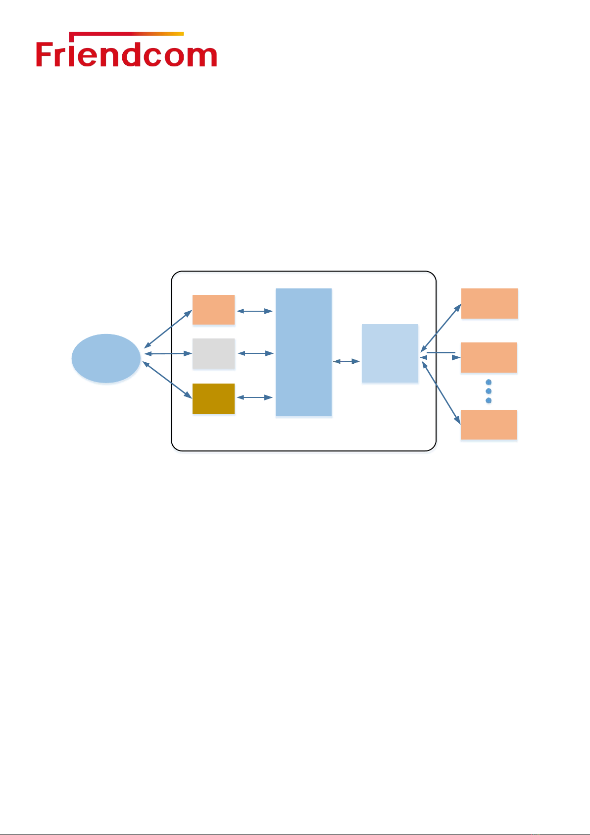
Product overview.................................................................................................................................. 6
2.1
General Description
............................................................................................................................6
2.2
Technical specifications
..................................................................................................................... 7
2.3
Technical specifications................................................................................................................... 8
2.4
LoRa Specifications.......................................................................................................................... 9
3
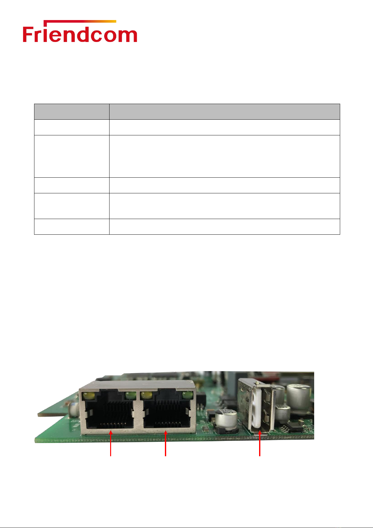
Hardware Resources........................................................................................................................... 9
3.1
Network interface.............................................................................................................................. 9
3.2
Power interface................................................................................................................................10
3.3
The Button........................................................................................................................................10
3.4
Indicator light....................................................................................................................................11
4
Quick start........................................................................................................................................... 12
4.1
Web interface login......................................................................................................................... 12
4.2
Status................................................................................................................................................14
4.2.1
Overview................................................................................................................................ 14
4.2.2
Firewall................................................................................................................................... 15
4.2.3
Routes.................................................................................................................................... 15
4.2.4
System Log............................................................................................................................16
4.2.5
Kernel Log..............................................................................................................................16
4.2.6
Processes.............................................................................................................................. 17
4.2.7
Realtime Graphs...................................................................................................................17
4.3
System..............................................................................................................................................19
4.4
Network.............................................................................................................................................22
4.4.1
LoRa GW............................................................................................................................... 22
4.4.2
WiFi.........................................................................................................................................22
4.4.3
Interfaces............................................................................................................................... 23
4.4.4
DHCP and DNS.................................................................................................................... 24
4.4.5
Diagnostics............................................................................................................................ 24
5
Connected to the Network Server....................................................................................................26
6
LoRaWAN Communication Example.............................................................................................. 29
7
Factory Data Reset............................................................................................................................ 34
8
To upgrade the firmware................................................................................................................... 34
8.1
USB port local update firmware....................................................................................................34
8.2
WEB remote update firmware.......................................................................................................35
9
Frequently Asked Questions............................................................................................................ 35

Page 6
GW300 LoRaWAN Gateway User Manual
1
Introduction
GW300 is an intelligent gateway for industrial Internet of Things integrating Lora, WiFi,
4G/3G, GPS and POE functions. It can be applied to smart agriculture, smart city,
wireless meter remote collection, M2M/LPWAN, fire safety and other fields. It is
independently developed by FRIENDCOM (Shenzhen) Co., Ltd.GW300 has the
characteristics of simple operation, convenient installation, high reliability, high waterproof
rating, etc., which can be easily realized in a variety of complex environment.
The LoRaWAN communication structure block diagram is shown as follows:
LoRaWAN Gateway
Network
Server
LoRaWAN
Node n
Ethernet
LoRaWAN
Node 2
4G/3G
SX1301
+
SX1257/
SX1255
WIFI
LoRaWAN
Node 1
ARM
Figure 1-1 LoRaWAN communication structure block diagram
2
Product Overview
2.1
General Description
GW300 Gateway integrates Lorawan, WiFi, 4G/3G, GPRS and POE functions. WiFi
supports AP mode and Station mode (not yet open), POE power supply and external DC
power supply, and supports 4G wireless or Ethernet connection to Network Server.GW300
supports WIFI wireless function, and supports external devices to be configured through
WIFI access gateway. At the same time, the built-in GPS module in the gateway can
provide accurate positioning function, which is convenient for users to manage the location
information of terminal devices.
The GW300 Industrial Gateway features a high-performance TI Cortex-A8 core and
integrates the SX1301+SX1257 LoRa baseband processing chip to support eight multi-SF
channels (SF12 to SF7), one single-SF channel and one high-speed GFSK channel. The
output power can be up to 26dBm and the sensitivity is -141dBm@SF12. A single gateway
can access tens of thousands of nodes under specific transmission periods and data

Page 7
GW300 LoRaWAN Gateway User Manual
lengths.
GW300 gateway is divided into several sub-models according to different frequency bands,
and the frequency band information of each sub-model is shown in the table below:
Table 2-1 GW300 gateway sub-model frequency band
Model
Frequency range
Support
GW300-470
470MHz~510MHz
CN470
GW300-868
862MHz~870MHz
IN865, EU868
GW300-915
900MHz~930MHz
AU915, US915, AS920, AS923
2.2
Technical Specifications
Technical specifications of GW300 gateway are shown in the following table:
Table 2-2 GW300 Technical specifications
Item
Project name
Functional description
System
Configuration
Kernel
TI Cortex-A8
Main frequency
800MHz
RAM
256MB DDR3 SDRAM
Flash
256MB NAND Flash
Operating system
Linux 3.18.91
Communication
mode
WAN Port
10/100/1000Mbps Ethernet with PoE
LAN Port
10/100Mbps Ethernet
WiFi
2.4~2.4835GHz, the highest rate is 150Mbps
GPRS/3G/4G
Support LTE-FDD, LTE-TDD, WCDMA, TDSCDMA,
CDMA, GSM
Wireless transmission
LoRa
Electrical
characteristics
Power supply input
PoE +48V input, IEEE 802.3 af/at
10~56V DC input
Average power
consumption typical
5W
Maximum power
consumption typical
15W (full load operation)
LoRa output power
Typ. 14dBm@868MHz
LoRa receiving sensitivity
-141dBm @ SF12, BW=125KHz
User interface
(external interface)
4G antenna interface
Wireless network connection network server
LoRaWAN antenna
interface
LoRaWAN wireless data collection
GPS antenna interface
Connect external GPS antenna to output GPS position
information

Page 8
GW300 LoRaWAN Gateway User Manual
WiFi antenna interface
AP mode supports external device connection gateway
PoE interface
10/100/1000Mbps Ethernet wired connection network
server
External DC power
supply interface
10~56V DC input port
Working
environment
Operating temperature
-40°C~+85°C (WiFi -10°C~+50°C)
Storage humidity
-40°C~+85°C (WiFi -40°C~+70°C)
Operating humidity
10% to 90% RH non-condensing
General
characteristics
External dimensions
230(L) x 230(W) x 100(H) mm
Weight
3.05kg
Installation mode
Pole mounting
2.3
Technical Specifications
Technical specifications of GW300 gateway are shown in the following table:
Table 2-3 GW300 Software Specification
Item
Functional description
Internet Connectivity
- thru WAN port with fixed IP/ DHCP client/ PPPoE
- thru 3G/4G
WiFi Configuration
SSID/ Encryption
Network Configuration
- DHCP server for IP leasing
- Diagnostics with Ping, TraceRoute and NSlookup
System Status
- Overview with system, software version, memory usage and wireless
configuration
- System Log shows system console information
- Kernel Log shows kernel information
- Processes shows running process information
- Real-time graphs shows system load, inbound/outbound traffic and IP
connections
LoRa Information
- Current LoRa channel configuration and Gateway ID
- Supported spreading factors
- External network server configuration and logs
Time Sync
- Support Network Time Protocol (NTP)
- Sync up with browser’s time
Firmware Upgrade
- Over-the-air (OTA) upgrade
- Thru USB port

Page 9
GW300 LoRaWAN Gateway User Manual
2.4
LoRa Specifications
The LoRa specifications of GW300 gateway are shown in the following table:
Table 2-4 GW300 LoRa Specifications
Item
Functional description
Protocol Standard
LoRaWAN™ Specification V1.0.2
LoRa Classes
- Class A: supported
- Class B: to be supported in later release
- Class C: supported
ADR
Adaptive data rate is supported to control the spreading factor of nodes
Activation
- Activation-by-Personalization (ABP)
- Over-the-Air Activation (OTAA)
MAC Commands
LoRaWAN™ Specification V1.0.2
3
Hardware Resources
GW300 gateway in order to user easy to use, retain some user interfaces for user
debugging, such as a key to restore factory Settings button, USB firmware upgrade
interface, LAN interface, etc. At the same time, you can know the working state of the
gateway according to the state of the display light on the motherboard.
3.1
Network Interface
The GW300 gateway provides a standard Ethernet interface, as shown below:
① ② ③
Figure 3-1 GW300 Network Interface

Page 10
GW300 LoRaWAN Gateway User Manual
The description is as follows:
Num
Description
①
WAN port, PoE connection port, used to connect to a wide area network
②
LAN port, can be directly connected with the PC end, through access to the
Web interface for parameter configuration
③
USB port, available for gateway firmware upgrade
3.2
Power Interface
The GW300 gateway provides POE and direct power supply, and the direct power supply
adopts DC power supply. The interface is shown in the figure below:
+-
①②③
Figure 3-2 GW300 Power interface
The description is as follows:
Num
Description
①
TF card holder, debug port, not open
②
Direct DC power supply interface, power supply range 10~56V
③
SIM card holder, for 4G uplink network, currently supports micro-SIM card
3.3
The Button
GW300 Gateway supports one-key restoration of factory Settings. Two keys are retained on
the gateway motherboard, as shown in the figure below:

Page 11
GW300 LoRaWAN Gateway User Manual
①②
Figure 3-3 GW300 Button
The description is as follows:
Num
Description
①
Processor reset button, press the system reset and restart
②
Restore factory Settings button. After pressing, all parameters will be restored to
default configuration. Long press 5s or more is effective
After the factory Settings button is pressed, all parameters will be restored to their default configuration.
At this time, all parameters need to be reconfigured.
3.4
Indicator light
GW300 can know the working situation through the status of the indicator light, which is
convenient for users to debug, as shown in the figure below:
②
①

Page 12
GW300 LoRaWAN Gateway User Manual
Figure 3-4 GW300 Indicator light
The description is as follows:
Num
Description
①
The red color, which flashes when the factory Settings are restored, indicates that
the gateway is performing the factory Settings restoration action
②
Green, always bright indicates that the gateway network connection is normal, can
surf the Internet
4
Quick Start
GW300 has two ways to enter the configuration mode through wireless WiFi and wired LAN
network port.In the wireless way, the gateway is connected to WiFi to access the hot spots
routed from AP mode.In wired mode, the LAN port on the gateway mainboard is directly
connected through PC, and the parameters are configured through Web interface.
4.1
Web interface login
GW300 built-in Web interface for users to configure parameters, users can access
"192.168.1.1" to enter the Web configuration interface.Default login username: root and
password: friendcom.GW300 factory default AP mode, provides two ways to log in the Web
interface.
1
)
Open the wireless scanning device SSID (WiFi name) through the computer, find the
wireless network of "Lorawan-GW-Friendcom", click the connection network, enter the
default password "Password" to connect to the WiFi hotspot of GW300, and access
192.168.1.1 with the browser to enter the Web configuration page.
2
)
Connect directly with PC through LAN interface using network cable, access
192.168.1.1 using browser to enter Web configuration page.
The login steps for GW300 are as follows:
Step 1: Enter IP "192.168.1.1" in the browser and open the interface as shown below:

Page 13
GW300 LoRaWAN Gateway User Manual
Figure 4-1 GW300 login interface
Step 2: Enter Username and password. Default Username: root;The Password: friendcom,
login interface is shown below:
Figure 4-2 GW300 Login interface
GW300 Web The general interface menu is as follows:
一级菜单:
Status:mainly displays the Status of the system
Network:Network related configuration, provides the gateway

Page 14
GW300 LoRaWAN Gateway User Manual
Internet mode setting, Network testing and other functions
System:Common System Settings
Logout:Exit the configuration
4.2
Status
The Status menu contains the following categories: Overview, Firewall, Routes, System Log,
Kernel Log, Processes, and Realtime Graphs, which are described below.
4.2.1
Overview
The Overview category can be used to view system status, memory usage, and network
Settings, as shown in the figure below:

Page 15
GW300 LoRaWAN Gateway User Manual
Figure 4-3 Overview Interface
In the upper right corner of the Overview screen, there is an "Auto Refresh On/Off" button in
the upper right corner of the panel. This function refreshes the status data every 5
seconds.By default, it is "Auto Refresh On" (green state). Click the Change button to turn
this function OFF, that is, "Auto Refresh Off" (gray state).
4.2.2
Firewall
The Firewall is used to view Firewall status information, including IPv4 Firewall and IPv6
Firewall.
4.2.3
Routes
The Routes is used to view the ARP table and IPv4 / IPv6 routing information, as shown
below:

Page 16
GW300 LoRaWAN Gateway User Manual
Figure 4-4 Routes interface
4.2.4
System Log
System Log is used to view System log information, as shown in the figure below:
Figure 4-5 System Log Interface
4.2.5
Kernel Log
Kernel Log is used to view the kernel log information, as shown in the figure below:
Figure 4-6 Kernel Log Interface

Page 17
GW300 LoRaWAN Gateway User Manual
4.2.6
Processes
Processes is used to see the progress of the System processes in which you are running, and
can suspend, terminate, and terminate individual process items for each process.
Figure 4-7 Processes Interface
4.2.7
Realtime Graphs
Realtime Graphs is used to view real-time chart information: Realtime Load、
Realtime Traffic、
Realtime Wireless、Realtime Connections.
1
)
Realtime Load
Realtime Load is used to view the current load value and the average value of different time
intervals, as shown below:
Figure 4-8 Realtime Load Interface

Page 18
GW300 LoRaWAN Gateway User Manual
2
)
Realtime Traffic
Realtime Traffic is used to view real-time data interaction information, as shown below:
Figure 4-9 Realtime Traffic Interface
3
)
Realtime Wireless
Realtime Wireless is used to view the current wireless network information, as shown below:
Figure 4-10 Realtime Wireless Interface
4
)
Realtime Connections

Page 19
GW300 LoRaWAN Gateway User Manual
Realtime Connections is used to view the current wireless network information, as shown
below:
Figure 4-11 Realtime Connections Interface
4.3
System
The System menu contains the following categories: System, Administration, Software, Startup,
Schedured Tasks, LED Configuration, Backup/Flash Firmware, and Reboot, which are described
below.
4.3.1
System
You can customize the hostname and time zone in the System properties.Click "SYNC WITH
BROWSER" (WITH BROWSER synchronization) button to adjust the local time, check the
"Enable the NTP client" (check mark next to Enable the NTP client) to synchronize the NTP server
time, if you choose to use other NTP server, please check the check mark next to the
"dojo.provide NTP server" (NTP server) and fill in "the NTP server candidate" text field.Different
languages can be applied according to the purpose (English and simplified Chinese are
supported).
After the setting is completed, you need to click the Save&Apply button in the lower right corner to take
effect;
Clicking the Save button will SAVE the user configuration information, but it will not take effect;
Click the Reset button to restore the default configuration;

Page 20
GW300 LoRaWAN Gateway User Manual
Figure 4-12 System Interface
4.3.2
Administration
Administration can configure the login password and other information of the gateway. Click
the symbol on the right to see the plaintext of the password, as shown below:
Figure 4-13 Administration Interface
4.3.3
Backup / Flash Firmware
Backup/ Flash Firmware allows you to Backup or restore the gateway's Settings and update
the gateway's Firmware.Click the 'Generate Archive' button in the Backup/ Restore column to
Backup the Gateway Settings, and click the 'Upload Archive' button to load the saved Gateway
Settings.
Click the "Flash Image" button in the Flash New Firmware Image column to load the new
gateway firmware and update the gateway firmware.
Table of contents