FRIENDCOM FC-302 User manual

FC-302 Data Radio
User Manual
Address: Comprehensive building, Wanyelong science and technology Park,
Liyuan Industrial Zone, Shiyan Street, Bao'an District, Shenzhen City 518108
P.R.CHINA.
Tel: +86-755-86026600 +86-755-23230518
Fax: +86-755-86026300
E-mail: [email protected]
Website: http://www.friendcom.com
SHENZHENG FRIENDCOM TECHNOLOGY DEVELOPMENT CO., LTD

1
FCC RF Exposure Compliance Requirements
The Federal Communications Commission (FCC), with its action in General Docket
93-62, November 7, 1997, has adopted a safety standard for human exposure to
Radio Frequency (RF) electromagnetic energy emitted by FCC regulated equipment.
Friendcom subscribes to the same safety standard for the use of its products. Proper
operation of this radio will result in user exposure far below the Occupational Safety
and Health (OSHA) and Federal Communications Commission limits.
About your FC-302 Series Data Radio
FC-302 is a PLL synthesized 5-watt FM transceiver module, which is designed for
data transmission and voice communication. It can support pre-emphasis, squelch
CTCSS/DCS and audio amplifier. Two-point modulation technology makes good low
frequency response and POCSAG application possible. The radio has fast start-up
time and makes it a competitive choice for 1200-19200bps rate data application.
Compact dimension and wide range DC support make it flexible to use.
Should you have questions regarding the operation of the radio, please consult us.

2
Features
CE, FCC& AS/NZS 4295: 2015 certified
Programmable 16 channels
Configurable power save feature
FSK, 4FSK& GMSK modem option
Frequency step 6.25KHz
CTCSS/DCS
Support maximum RF data rate: 19200bps
Fast start-up time: 5ms
SQ programmable via PC
POCSAG Modulation
PC programmable & Software tune & Calibration
Applications
Industrial telemetry & wireless remote control or Paging system
Gas and oil flow monitoring
Electricity, water and gas utilities
Earthquake, weather, environmental protection
Vehicle tracking and asset tracking systems
Water monitoring, waste water management and irrigation control
Railway, police, army automation system
Aerial defense and fire alarm system
Urban lighting control

3
Specifications
GENERAL
Working Frequency
V: 136-174MHz
U0: 400-440MHz
U1: 430-470MHz
U2: 450-490MHz
Channel Spacing
12.5KHz/25KHz Programmable
Modulation Type
F3D/F3E
Number of Channels
16
Nominal Working Voltage
12V DC
Extreme Working Voltage
9.6 V~16V DC
Storage Temperature
-40℃~+80℃
Operating Temperature
-30℃~+65℃
Current
Consumption
Standby
<100mA
Transmit 5 watts RF Power
<1.5A
Transmit 1 watt RF Power
<1A
TX to RX Attack Time
<5ms
RX to TX attack time
<5ms
Frequency Error
<2.5ppm
Antenna Connector
BNC 50Ω
External interface
DB15 Female

4
TRANSMITTER Specification
RF Power
1W/2W/3W/4W/5W Programmable
Frequency
Deviation
25KHz Channel Spacing
<5KHz
12.5KHz Channel Spacing
<2.5KHz
Subsonic
0.5KHz
Audio Response
25KHz Channel Spacing
300Hz~3KHz +1/-3dB
12.5KHz Channel Spacing
300Hz~2.55KHz +1/-3dB
Adjacent
Channel Power
25KHz Channel Spacing
<-70dBc
12.5KHz Channel Spacing
<-65dBc
Conducted Spurious Emission
<1GHz,<-36dBm
>1GHz,<-30dBm
Modulation
Sensitivity
Voice
8~15mV
Data
80~130mV
TX SNR
25KHz Channel Spacing
>45dB
12.5KHz Channel Spacing
>40dB
RECEIVER Specification
RX Sensitivity
(12dB SINAD)
25KHz Channel Spacing
<-119dBm Extreme<-115dBm
12.5KHz Channel Spacing
<-119dBm Extreme<-115dBm
Adjacent Channel
Selectivity
25KHz Channel Spacing
>70dB
12.5KHz Channel Spacing
>60dB
Image Rejection
>70dB
5
IF Rejection
>70dB
Spurious Rejection
>70dB
Intermodulation Suppression
>65dB
Conducted Spurious Emission
<-57dBm
Receiving Audio Distortion
<5%
RX SNR
25KHz Channel Spacing
>45dB
12.5KHz Channel Spacing
>40dB
Audio Output Power
0.5W @ 8Ωload
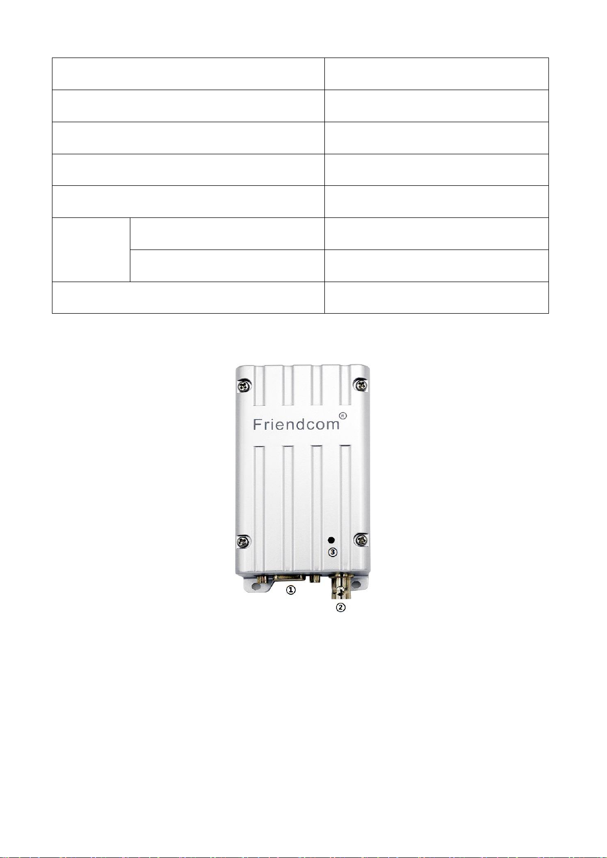
Exterior View
Description of radio components
①DB15 Female connector
②BNC Antenna connector
③LED(Red for TX, Green for RX)
6
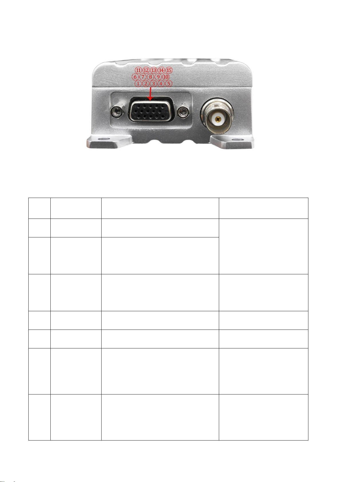
FC-302 External DB15 female Pin Assignment
FC-302 is manufactured by default with modem, if the radio does not have a built-in
modem; the corresponding pin is defined as empty.
Pin
No.
Function
Description
Note
①
AUDIO_IN
(MOD IN)
Audio input, 3Khz LPF, Modulation
sensitivity is 100mV.
AUDIO_IN is effective only
when Pin7 (MIC) is vacant or
with +5V high level. 3KHz
LPF filter existed in audio
channel.
②
AUDIO_OUT
(AF OUT)
Audio output, 3Khz LPF. Output level at
60% frequency deviation is 250±50mV.
This line has an internal pull-up resistor
to +5V.
③
PTT
TX control, active low, only when PTT is
active AUDIO_IN and MIC IN are
effective. This line has an internal pull-
up to 5V.
④
B+
(9.6~16V DC)
Positive pole input from DC power,
nominal +12V.
⑤
PROG
(DATA OUT)
Programming data output, 5V TTL
⑥
BUSY
Logical level output to indicate
whether there is a carrier or not. Low
lever means carrier, high level means
no carrier. This line has a pull-up to
+5V.
⑦
MIC IN/RSSI
MIC IN: Microphone input.
RSSI: To detect the air signal strength.
Jumper selectable.
Can directly connect to
electrets MIC, the DC voltage
of this pin should lower than
3.5V, then MIC transmission
can be activated.

7
⑧
PROG
(DATA IN)
Programming data input, 5V TTL
⑨
SPK/POCSAG
SPK: Audio output from the audio
amplifier, @ 8Ω.
POCSAG: To transmit POCSAG code.
Jumper selectable.
AUDIO_IN is effective only
when PIN7 (MIC) is vacant or
with +5V high level. 3KHz
LPF filter existed in audio
channel.
⑩
RXD
(MODEM)
The serial data is input to modem
through this pin. Default is RS232.
The hardware is one of
RS232, RS485 or TTL/5V
when delivery.
⑪
TXD
(MODEM)
Serial data is output from modem via
this pin. Default is RS232.
The hardware is one of
RS232, RS485 or TTL/5V
when delivery.
⑫
CD_OUT
(MODEM)
Logical level output to indicated
whether a carrier or not. Low lever for
carrier, high level for no carrier.
⑬
NC
No connection
⑭
GND
Ground
⑮
NC
No connection
Antenna installation
Fasten the antenna to the radio by turning the antenna connector clockwise into the
receptacle on right of radio when looking at front of radio.
Powering the data radio
FC-302 accepts many sources of DC power to permit more versatile use. This radio
operates from 9.6V to 16V DC and standard voltage for test is 12V DC. The 4th pin of
DB15 female connector for radio's power input pin.
FC-302 Function
Channel Spacing
The radio is capable of programmable channel spacing, having 12.5KHz or 25KHz
channel spacing.

8
SQ (Squelch) Level
Five SQ levels are set in the radio and can be selected by PC software.
Level 0 is for fully open mute. The audio signal will continuously transmit. Other
levels are shown as below:
Level 1:0.15uV
Level 2:0.25uV
Level 3:0.35uV
Level 4:0.45uV
Level 5:0.55uV
CTCSS/DCS
To help to block out unwanted calls to your radio, FC-302 can be programmed by
software to set CTCSS/DCS code. When enabled, receiver only can receive useful RF
signal with the same CTCSS/DCS code of the transmitter to avoid interference from
useless signal. For fast lock time, the CTCSS/DCS is not available for high speed data
transmission.
Channel Scan
The radio enables to detect the channels by initiate scanning mode. Scanning mode
is optional and programmable. This PC software allows user to decide scan mode
and establish channel scanning sequence. Four scan modes are provided in “Option”
and shown as below:
0 ---------normal scan with carry only

9
1 ---------normal scan, Carry with tone
2 ---------priority scan, Carry only
3 ---------priority scan, carry with tone
Channel Select
FC-302’s 16 channels can be selected by inner dip (4) switch (HW) on power board
or serial command inputted from our PC software (SW). Only in SW control mode,
channel can be selected by PC software in “Channel” feature. It is recommended
to change it via SW.
Channel dip switch chart
TX Protection
This feature, when enabled, limits the amount of time that the radio can
continuously transmit for protecting the radio from block of the channel and
damage on radio which is caused by sustained transmission. In TX mode, if PTT is
effective all through and exceed set time, radio will stop transmitting automatically
until restart the PPT again. The time can be set by PC software.
Other manuals for FC-302
2
Table of contents
Other FRIENDCOM Radio manuals


