OPERATING
INSTRUCTIONS
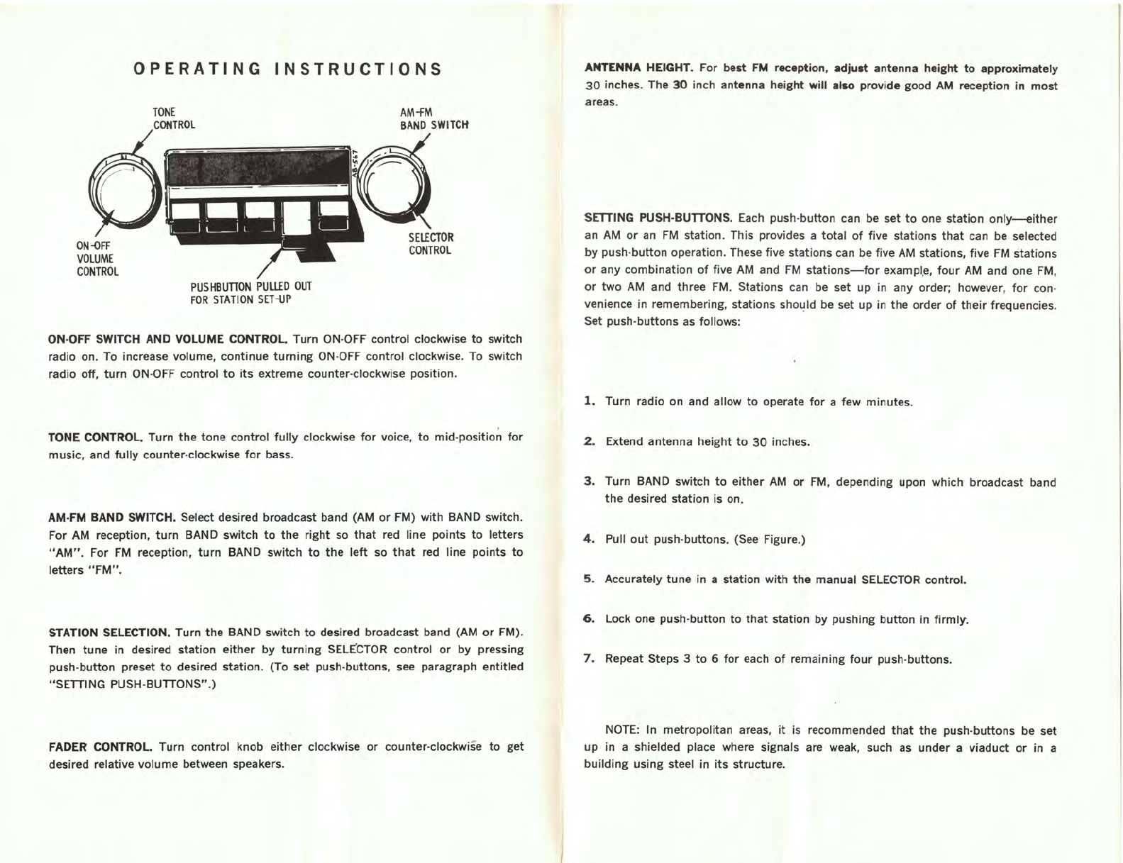
TONE
CONTROl
PUSHBunON
PUllED
OUT
FOR
STATION
SET-UP
AM-fM
BAND
SWITCIt
ON·OFF SWITCH AND
VOlUME
CONTROL Turn ON-OFF controi clockwise
to
switch
radio
on_
To increase volume, continue
turning
ON-OFF controi clockwise_ To switch
radio off,
turn
ON-OFF controi
to
its
extreme counter-clockwise position_
TONE CONTROl. Turn
the
tone
controi
fully
clockwise
for
voice,
to
mid-position
for
music, and
fully
counter-clockwise
for
bass_
AM·FM BAND
SWITCH_
Select desired broadcast band (AM
or
FM) with BAND switch_
For AM reception,
turn
BAND switch
to
the
right
so
that
red line points
to
letters
"AM"_
For
FM
reception,
turn
BAND switch
to
the
left
so
that
red line points
to
letters
"FM"_
STATION SElECTION. Turn
the
BAND switch
to
desired broadcast band (AM
or
FM).
Then
tune
in desired station
either
by
turning
SElECTOR controi
or
by
pressing
push-button preset
to
desired station. (To set push-buttons, see paragraph entitled
"SETTING PUSH-BUTTONS".)
FADER CONTROL Turn controi knob
either
clockwise
or
counter-clockwise
to
get
desired relative volume between speakers.
ANTENNA
HEIGHT_
For best
FM
reception,
adjult
antenna
height
to
approximately
30
inches. The
30
inch antenna height
will
allo
provide good
AM
reception
in
most
areas.
SETTING PUSH-BUTTONS. Each push-
button
can be set
to
one station
only-either
an AM
or
an
FM
station. This provides a
total
of
five stations
that
can be selected
by
push-
button
operation. These five stations can be five
AM
stations, five
FM
stations
or
any combination
of
five
AM
and
FM
stations-for
exampl,
e,
four
AM
and
one
FM,
or
two
AM and three
FM
. Stations can be set up in any order; however,
for
con-
venience in remembering, stations should be set up in the order
of
their
frequencies_
Set push-buttons
as
follows:
l.
Turn radio on and allow
to
operate
for
a few minutes.
2.
Extend antenna height
to
30
inches.
3.
Turn BAND switch
to
either
AM
or
FM
, depending upon which broadcast band
the
desired station is on.
4.
Pull
out
push-buttons. (See Figure.)
5.
Accurately
tune
in a station
with
the
manual SElECTOR controI.
6.
lock
one push-button
to
that
station
by
pushing
button
in
firmly
.
7.
Repeat Steps 3
to
6
for
each
of
remaining
four
push-buUons.
NOTE: In metropolitan areas,
it
is recommended
that
the
push·buUons be set
up
in a shielded place where signals are weak, such
as
under a viaduct
or
in a
building
using steel in
its
structure.