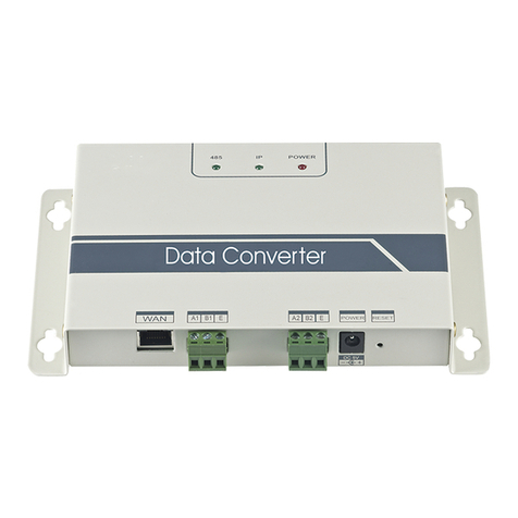
Frigicoll GW-KNX(A) User manual

Owner's Manual
Hydraulic Module KNX Gateway
GW-KNX(A) - (K05-KNX 01 A)
Thank you for purchasing our product.
Read this manual carefully before using this product and keep it for future reference.

● Thismanualgivesdetaileddescriptionoftheprecautions
that should be brought to your attention during operation.
● InordertoensurecorrectserviceofGW-KNX(A)-(K05-
KNX 01 A), please read this manual carefully before using
the unit.
● Forconvenienceoffuturereference,keepthismanual
after reading it.

Table of Contents
I.Safetyprecautions........................................................................................ 1
II.Otherprecautions........................................................................................ 3
III.Installationprocedure ................................................................................. 5
IV.ETSdatabasegroupobjectsintroduction .................................................. 8

1
I. Safety precautions
The following contents are stated on the product and the operation
manual, including usage, precautions against personal harm and
property loss, and the methods of using the product correctly and safely.
Afterfullyunderstandingthefollowingcontents(identiersandicons),
readthetextbodyandobservethefollowingrules.
Identierdescription
Icondescription
Identier Meaning
Warning Means improper handling may lead to
personalsevereinjury.
Caution Means improper handling may lead to
personalinjury.
[Note]:1.“Harm”meansinjury,burnandelectricshockwhichneed
long-term treatment but need no hospitalization.
2. “Property loss” means loss of properties and material.
lcon Meaning
Itindicatesforbidding.Theforbiddensubject-matteris
indicated in the icon or by images or characters aside.
Itindicatescompulsoryimplementation.Thecompulsory
subject-matterisindicatedintheiconorbyimagesor
characters aside.

2
WARNING
CAUTION
Please entrust the distributor or professionals to install the unit.
Strictly follow this manual.
Reinstallation must be performed by professionals.
Do not disassemble your air conditioner at will.
Do not install the unit in a place vulnerable to leakage of ammable gases.
The wiring should adapt to the wire controller current.
The specied cables shall be applied in the wiring. No external force may
be applied to the terminal.
Do not place the wired remote controller near the lamps, to avoid the remote
signal of the controller to be disturbed. (refer to the right gure)
Installationbyotherpersonsmayleadtoimperfectinstallation,electricshockorre.
Imporperinstallationmayleadtoelectricshockorre.
improperinstallationmayleadtoelectricshockorre.
Arandomdisassemblymaycauseabnormaloperationorheating,whichmayresultinre.
Onceammablegasesareleakedandleftaroundthewirecontroller,remayoccure.
Otherwise,electricleakageorheatingmayoccurandresultinre.
Otherwise,wirecutandheatingmayoccurandresultinre.

3
II. Other precautions
InstallationLocation
Preparation before installation
Donotinstalltheunitinaplacewithmuchoil,steam,suldegas.Otherwise,the
product may be deformed and failed.
1. Check whether the following assemblies are complete.
No. Name Qty. Remarks
1GW-KNX(A) - (K05-KNX 01 A) 1
2Cross round head wood
mounting screw 3GB950-86M4X20(ForMountingontheWall)
3Cross round head mounting
screw 2M4X25 GB823-88
(ForMountingontheElectricalSwitchBox)
4InstallationManual 1
5Plastic expansion pipe 3 ForMountingontheWall
63-core shielded cable 1 ForconnectingtheindoorunitandGW-
KNX(A) - (K05-KNX 01 A)

4
2. Prepare the following assemblies on the site.
Note to installation of GW-KNX(A) - (K05-KNX 01 A):
1. One KNX module can only connect with one indoor unit;The KNX module should
connecttoindoorD1D2Eports.
2.CircuitofGW-KNX(A)-(K05-KNX01A)islowvoltagecircuit.Neverconnect
itwithastandard220V/380VcircuitorputitintoasameWiringTubewiththe
circuit.
3. Do not attempt to extend the shield cable by cutting, if it is necessary, use
Terminal Connection Block to connect.
4.Afternishingconnection,donotuseMeggertohavetheinsulationchecktothe
signal wire.
5.ThedefaultphysicaladdressoftheGW-KNX(A)-(K05-KNX01A)is15.15.255,If
there are two or more KNX modules, then the physical addresses can not repeat.
ThephysicaladdresscanbechangedbyETSsoftware.
No. Name Qty.(embeded
into wall)
Specication(only
for reference) Remarks
12-core shielded cable 1 RVVP-0.5mm2x2 Max 350m
286Electricianbox 1
3
WiringTube(Insulating
SleeveandTightening
Screw)
1
4KNX power module 1
5Communicate module 1

5
III. Installation procedure
1. The product parameters
2. The product parameters
No. Name Remarks
1Dimensions 85*51*16mm
2Power supply 29VDC10mA,SuppliedthroughKNXbus
3LEDindicator KNX programming
4Push button KNX programming button
5Conguration CongurationwithETSsoftware.
GW-KNX(A)
E
AC Unit
①
②
③
④

6
Bus interface:PowersupplyDC29V,10mAandconnecttoKNXbus;
RS485 communication ports: Communication port between KNX module
and indoor unit.(support 2nd generation DC indoor unit)
GW-KNX(A)-(K05-KNX01A)iscompletelyinconformitywithEIB/
KNXstandard.ETSsoftwaremustbeusedbyintegratortocarryout
congurationandprojectdesign.FordetailedinformationofETSsoftware,
please contact knx association: www.knx.org.
ETSdatabase(*.knxprod*)ofGW-KNX(A)-(K05-KNX01A)canbe
downloadedfromourwebsite:http://cac.midea.com,orconsultour
company.
The Wiring diagram follows,the GW-KNX(A) - (K05-KNX 01 A) connect to
the indoor Unit and KNX Power.
KNX programming button: press once to enter the programming mode,
press it again will exit.
KNX programming statues lamp: when it is light up means programming
status and can write data to the module by KNX bus
3. Wiring installation instruction
+-
E
D2
D1
E
D2
D1
indoor unit
GW-KNX(A)
KNX TP-1
(EIB) bus
MAX 500m
.

7
TheIntroductionGW-KNX
Simpleinstallation.
GreatexibilityofintegrationintoyourKNXprojects.
Allows the use of a KNX temperature sensor for the air conditioning control.
GW-KNX allows monitoring and control, fully bi-directionally, of all the functioning
parameters of Midea Air Conditioners from KNX installations.
Can be installed inside the own indoor unit, it connects directly in one side to the
electronic circuit of the indoor unit (cable supplied) and in the other side to the KNX
TP-1(EIB)bus.
CongurationismadedirectlyfromETS,thedatabaseofthedevicecomeswitha
completesetofcommunicationobjectsallowing,fromasimpleandquickintegration
usingthebasicobjects,tothemostadvancedintegrationwithmonitoringandcontrol
alltheindoorunit’sparameters.Alsoavailablespecicdevice’scommunication
objects,asforexamplesaveandexecutescenes.

8
IV. ETS database group objects introduction
1)Whenthegatewayispoweredon,itscanstheIDUtoobtaintheIDUdatathatcan
becommunicatedrst.
2)TheKNXbuscontrolcommandisparsedandrepackagedintotheIDUD1D2E
communicationprotocolformat,andthensenttotheIDU.
3) KNX access points:
Function Group
Address Length Data Type Function Attribute Remarks
On/offinheatingmode 0/0/1 1 bit Boolean Input CRW 0: Off
1: On
Water outlet temperature
control in heating mode 0/0/2 2 bytes F16/Float Input CRW 25-80 ºC
Room temperature control in
heating mode 0/0/3 2 bytes F16/Float Input CRW 17-30 ºC
On/offinwaterheatingmode 0/0/4 1 byte Boolean Input CRW 0: Off
1: On
Temp. control in water
heating mode 0/0/5 2 bytes F16/Float Input CRW 25-80 ºC
Current running mode 0/0/20 1 byte N8/
Enumeration Output CRT 0: Off
1: Heating
Setwateroutlettemperature
in heating mode 0/0/21 2 bytes F16/Float Output CRT ºC
Current water outlet
temperature in heating mode 0/0/22 2 bytes F16/Float Output CRT ºC

9
Function Group
Address Length Data Type Function Attribute Remarks
Setroom
temperature in
heating mode
0/0/23 2 bytes F16/Float Output CRT ºC
Current room
temperature in
heating mode
0/0/24 2 bytes F16/Float Output CRT ºC
Settemperature
in water heating
mode
0/0/25 2 bytes F16/Float Output CRT ºC
Current
temperature in
water heating
mode
0/0/26 2 bytes F16/Float Output CRT ºC
Enablingthewater
heating mode and
heating mode
0/0/27 1 byte Output CRT
0:Defaultvalue
1:Enablingthe
heating mode and
water heating mode
2: Water heating
mode, without heating
mode
3: Heating mode, with
water heating mode
Current control
status in heating
mode
0/0/28 1 byte N8/
Enumeration Output CRT
0:Defaultvalue
1: Water outlet
temperature control is
valid
2: Room temperature
controlisvalid

Function Group
Address Length Data Type Function Attribute Remarks
Lowbyteof
error code 0/0/29 1 bytes N8/
Enumeration Output CRT
N8/
Enumerationdenition
in the table below
High byte of
error code 0/0/30 1 bytes N8/
Enumeration Output CRT
N8/
Enumerationdenition
in the table below
Isthere
currently an
error
0/0/31 1 bytes N8/
Enumeration Output CRT 0: No error
1:Error
Notes:
C: Communication; R: Read; W: Write; T: Transmit
Denitionofhigh-temperaturehydraulicmoduleerror
Lowbyteoferrorcode+highbyteBit0oferrorcoderepresenttheerrorcategory;
High bytes Bit1 to Bit4 of error code represent the error sub-categories;
High bytes Bit5 to Bit7 of error code represent the error no.
10

11
Byte Meaning Value Remarks
Lowbyteoferror
code+Bit0ofhigh
byte of error code
Lowbyteoferror
code+Bit0ofhigh
byte of error code
0: No error
1-20:A0-AF,AH,AL,AP,AU
21-40:b0-bF,bH,bL,bP,bU
41-60:C0-CF,CH,CL,CP,CU
61-80:E0-EF,EH,EL,EP,EU
81-100:F0-FF,FH,FL,FP,FU
101-120:H0-HF,HH,HL,HP,HU
121-140:L0-LF,LH,LL,LP,LU
141-160:J0-JF,JH,JL,JP,JU
161-180:n0-nF,nH,nL,nP,nU
181-200:P0-PF,PH,PL,PP,PU
201-220:r0-rF,rH,rL,rP,rU
221-240:t0-tF,tH,tL,tP,tU
241-260:U0-UF,UH,UL,UP,UU
Others:reserved
High bytes Bit1 to
Bit4 of the error code Reserved 0
High bytes Bit5 to
Bit7 of the error code
represent the error
no. 0 to 7 0: no error No.
1 to 7: error No.
Examplesoferrorcodes
1)Ifthelowbyteoferrorcode+highbyteBit0oferrorcodeis1,thehighbytesBit1toBit4oferror
code is 0, and the high bytes Bit5 to Bit7 of error code is 0, the error code is A0.
2)Ifthelowbyteoferrorcode+highbyteBit0oferrorcodeis1,thehighbytesBit1toBit4oferror
code is 0, and the high bytes Bit5 to Bit7 of error code is 1, the error code is 1A0.
WP-MD20U-036A-EN
16110900000244V.A

This manual suits for next models
1
Table of contents
Other Frigicoll Gateway manuals