manuals.online logo
Brands
  1. Home
  2. •
  3. Brands
  4. •
  5. Frigidaire
  6. •
  7. Cooktop
  8. •
  9. Frigidaire FEF314BWB User guide

Frigidaire FEF314BWB User guide

Other Frigidaire Cooktop manuals

Frigidaire FPEC3085KSA User manual

Frigidaire

Frigidaire FPEC3085KSA User manual

Frigidaire FEF377CFTE Quick start guide

Frigidaire

Frigidaire FEF377CFTE Quick start guide

Frigidaire FEFB65ASD Quick start guide

Frigidaire

Frigidaire FEFB65ASD Quick start guide

Frigidaire FEF367CGTD Quick start guide

Frigidaire

Frigidaire FEF367CGTD Quick start guide

Frigidaire FGC36C4HWD User manual

Frigidaire

Frigidaire FGC36C4HWD User manual

Frigidaire FES367ASH Quick start guide

Frigidaire

Frigidaire FES367ASH Quick start guide

Frigidaire FGC30S4ASB User manual

Frigidaire

Frigidaire FGC30S4ASB User manual

Frigidaire FED367DSB Quick start guide

Frigidaire

Frigidaire FED367DSB Quick start guide

Frigidaire FEC36C2AQC User manual

Frigidaire

Frigidaire FEC36C2AQC User manual

Frigidaire FEC30S6ABC User manual

Frigidaire

Frigidaire FEC30S6ABC User manual

Frigidaire Gallery Series GLEC36S8CS Quick start guide

Frigidaire

Frigidaire Gallery Series GLEC36S8CS Quick start guide

Frigidaire FGC36C4AW - 36" Gas Cooktop User manual

Frigidaire

Frigidaire FGC36C4AW - 36" Gas Cooktop User manual

Frigidaire FPEC3085KS - 30" Electric Cooktop User manual

Frigidaire

Frigidaire FPEC3085KS - 30" Electric Cooktop User manual

Frigidaire Compact 30 User manual

Frigidaire

Frigidaire Compact 30 User manual

Frigidaire FEC30S6A User manual

Frigidaire

Frigidaire FEC30S6A User manual

Frigidaire Professional PLEF489GC User manual

Frigidaire

Frigidaire Professional PLEF489GC User manual

Frigidaire FGEC3645PS Instruction sheet

Frigidaire

Frigidaire FGEC3645PS Instruction sheet

Frigidaire FEFL74ASE Quick start guide

Frigidaire

Frigidaire FEFL74ASE Quick start guide

Frigidaire Gallery FGGC3065K S Manual

Frigidaire

Frigidaire Gallery FGGC3065K S Manual

Frigidaire FEF455BBE Quick start guide

Frigidaire

Frigidaire FEF455BBE Quick start guide

Frigidaire 318201451 User manual

Frigidaire

Frigidaire 318201451 User manual

Frigidaire GAS COOKTOP User manual

Frigidaire

Frigidaire GAS COOKTOP User manual

Frigidaire FPGC3677RS User manual

Frigidaire

Frigidaire FPGC3677RS User manual

Frigidaire PLGC36S9C User manual

Frigidaire

Frigidaire PLGC36S9C User manual

Popular Cooktop manuals by other brands

Fisher & Paykel CE302CBX2 manual

Fisher & Paykel

Fisher & Paykel CE302CBX2 manual

Whirlpool GJC3634RB00 parts list

Whirlpool

Whirlpool GJC3634RB00 parts list

Whirlpool ACH7324/BLV Use, care and installation guide

Whirlpool

Whirlpool ACH7324/BLV Use, care and installation guide

Bonnet OPTIMUM 700 Technical instructions

Bonnet

Bonnet OPTIMUM 700 Technical instructions

Jenn-Air JGCP430 installation instructions

Jenn-Air

Jenn-Air JGCP430 installation instructions

Bompani BO374AA/E User instructions

Bompani

Bompani BO374AA/E User instructions

Kleenmaid cooking GCTK9011 Instructions for use and warranty details

Kleenmaid

Kleenmaid cooking GCTK9011 Instructions for use and warranty details

Waldorf RN8603E-B Technical data sheet

Waldorf

Waldorf RN8603E-B Technical data sheet

Whirlpool SMP658CNEIXL quick guide

Whirlpool

Whirlpool SMP658CNEIXL quick guide

Electrolux E36IC80ISS - 36" Induction Cooktop Wiring diagram

Electrolux

Electrolux E36IC80ISS - 36" Induction Cooktop Wiring diagram

Wolf CI243C/B Use and care guide

Wolf

Wolf CI243C/B Use and care guide

Fulgor Milano F5PGK305S1 installation instructions

Fulgor Milano

Fulgor Milano F5PGK305S1 installation instructions

Wells WV-2HFG owner's manual

Wells

Wells WV-2HFG owner's manual

Samsung NA36N9755 installation manual

Samsung

Samsung NA36N9755 installation manual

Miele KM 404 operating instructions

Miele

Miele KM 404 operating instructions

Lacor 69562 Instructions for use and maintenance

Lacor

Lacor 69562 Instructions for use and maintenance

Keating Of Chicago MG-2 manual

Keating Of Chicago

Keating Of Chicago MG-2 manual

Jenn-Air CCE1400 Use and care guide

Jenn-Air

Jenn-Air CCE1400 Use and care guide

manuals.online logo
manuals.online logoBrands
  • About & Mission
  • Contact us
  • Privacy Policy
  • Terms and Conditions

Copyright 2025 Manuals.Online. All Rights Reserved.

If the infinite switch contacts are good, and the element does
not heat, check for voltage at the element receptacle. If no
voltageisindicated,checkforbrokenwiringorlooseconnec-
tions. If voltage is indicated, the problem is in the heating ele-
ment.
Indicator Light
If the elements heat up but the indicator light does not glow,
check for voltage at the indicator terminals. 240 VAC should
be present at the indicator terminals. If voltage is present at
theindicatorterminals,replacethe indicatorlight.If novoltage
is present at the
indicator terminals, check for loose connections, broken wir-
ing, or open L1-P contact in the infinite switch.
SurfaceElements
Ifthe heating element does notheatup, check for line voltage
at receptacle.Approximately 240 VAC should be indicated at
the
elementreceptacle with the infinite switchinthe HI position. If
novoltageisindicatedatreceptacle,check for loose connec-
tions, broken wiring, or a defective infinite switch. If voltage is
present at the receptacle terminals, check element for conti-
nuityusing proceduresbelow.
1.Shut off power to range.
2.Remove elementfromreceptacle.
3.Set ohmmeter to R X 10 scale and attach meter leads to
element.A low OHMS reading (continuity)shouldbe indi-
cated, and this reading may vary slightly on each element
tested. If infinite OHMS (open) is indicated, element must be
replaced(see Fig. 3).
Surface Elements (Infinite) Switch
The surface elements and controls provide an infinite choice
ofheat settings forcooking. Controls aresafety type andmust
be pushed in before turning. All surface controls are marked
onthecontrol panelfortheirrespectiveheatingelement.Power
is supplied to the surface elements through the infinite switch
contactsL1-H1 and L2-H2.
Continuity tests can be performed on the infinite switch con-
tacts. All tests should be performed with power to the range
disconnected, and wiring removed from the switch. Set an
ohmmeter on R X 1K scale and check the contacts in the
chart below (Fig. 1). The location of the switch terminals is
shown in Fig. 2.
NOTE:During actual surface element operation,contactsL2-
H2will cycle tomaintainthe correct heat setting.Contacts L1-
P provide power to the surface element indicator light.
THIS SERVICE DATA SHEET IS
INTENDED FOR USE BY PERSONS HAVING
ELECTRICAL AND MECHANICAL TRAINING AND A
LEVEL OF KNOWLEDGE OF THESE SUBJECTS
GENERALLY CONSIDERED ACCEPTABLE IN THE
APPLIANCE REPAIR TRADE. THE MANUFACTURER
CANNOT BE RESPONSIBLE, NOR ASSUME ANY
LIABILITY FOR INJURY OR DAMAGE OF ANY KIND
ARISING FROMTHE USE OFTHIS DATA SHEET.
DISCONNECTPOWERBEFORE SERVICING
IMPORTANT - RECONNECT ALL GROUNDING
DEVICES.ALL PARTS OFTHIS APPLIANCE CAPABLE
OF CONDUCTING ELECTRICAL CURRENT ARE
GROUNDED. IF GROUNDING WIRES, SCREWS,
STRAPS, NUTS ORWASHERS USED TO COMPLETE
A PATH TO GROUND ARE REMOVED FOR SERVICE,
THEY MUST BE RETURNED TO THEIR ORIGINAL
POSITION AND PROPERLY FASTENED.
Contacts Dial Position
OFF LO-MED HI
L1 - P O X X
L1 - H1 O X X
L2 - H2 OX - C X
Fig. 1
Fig. 2
SERVICE DATA SHEET - DO NOT DISCARD
P/N 316218511(0307)
IMPORTANT
DO NOT REMOVETHIS BAG
OR DESTROYTHE CONTENTS
WIRING DIAGRAMS AND SERVICE
INFORMATION ENCLOSED
REPLACE CONTENTS IN BAG
Fig. 3
BakeElement
If the bake element does not heat up, check for line voltage
across element terminals.Approximately 240VAC should be
indicated across terminals. If no voltage is indicated across
terminals,check for broken wire betweenthermostatand ele-
ment. Check thermostat. If voltage is present at the element,
check element for continuity using procedures below.
1.Shut off power to range.
2.Remove wireleadsfrom element terminals.
3.Set ohmmeter to R X 10 scale and attach meter leads to
element.AlowOHMS reading(continuity)shouldbe indicated.
IfinfiniteOHMS(open)isindicated,elementmustbereplaced.
Broil Element
If the broil element does not heat up, check for line voltage at
elementterminals.Approximately240VACshouldbeindicated
at the element. If no voltage is indicated across terminals,
checkforbroken wirebetween thermostatandelement.Check
thermostat. If voltage is present at the element, check ele-
ment for continuity using procedures below.
1.Shut off power to range.
2.Remove wireleadsfrom element terminals.
3.Set ohmmeter to R X 10 scale and attach meter leads to
element.Alow OHMSreading(continuity)shouldbe indicated.
IfinfiniteOHMS(open)is indicated,element mustbe replaced.
Thermostat Selector Switch
The temperature control is a combination thermostat and se-
lector switch assembly.The temperature control is performed
by cycling contacts in the thermostat.
The selection of bake or broil operation is done at the control
dial.The contacts C-BA are closed when a bake temperature
isselected.Thecontacts C-BRareclosed whenthebroil func-
tion is chosen.
Oven Indicator Light
The oven indicator light operates any time the thermostat se-
lectorswitch is placedinoperation. It willcyclewith the opera-
tion of the cycling contacts in the thermostat (glows with con-
tacts closed). It is a 240 VAC indicator light.
OHMS
TYPICALNON-SELF CLEAN RANGE
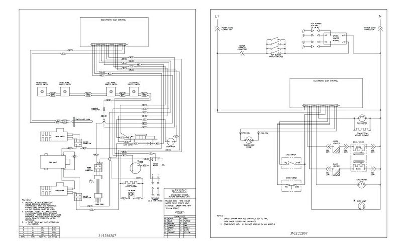
Schematic Diagram
SERVICE DATA SHEET (Cont'd) - DO NOT DISCARD