1. ANTI-TIPBRACKETINSTALLATIONINSTRUCTIONS
-IMPORTANTSAFETY WARNING
To reduce the risk of tipping of the range, the range must be
securedtothefloorbyproperlyinstalledAnti-TipBracketand
screwspacked withtherange. Failureto install theanti-tip bracket
will allow the range to tip over if excessive weight is placed on an
open door or if a child climbs upon it. Serious injury might result
from spilled hot liquids or from the range itself.
Ifrangeis evermovedto adifferentlocation, theAnti-TipBracket
must also be moved and installed with the range.
Instructionsareprovidedforinstallationinwood orcement
fastened to either the floor or wall. When installed to the wall,
make sure that screws completely penetrate dry wall and are
secured in wood or metal. When fastening to the floor or wall, be
sure that screws do not penetrate electrical wiring or plumbing.
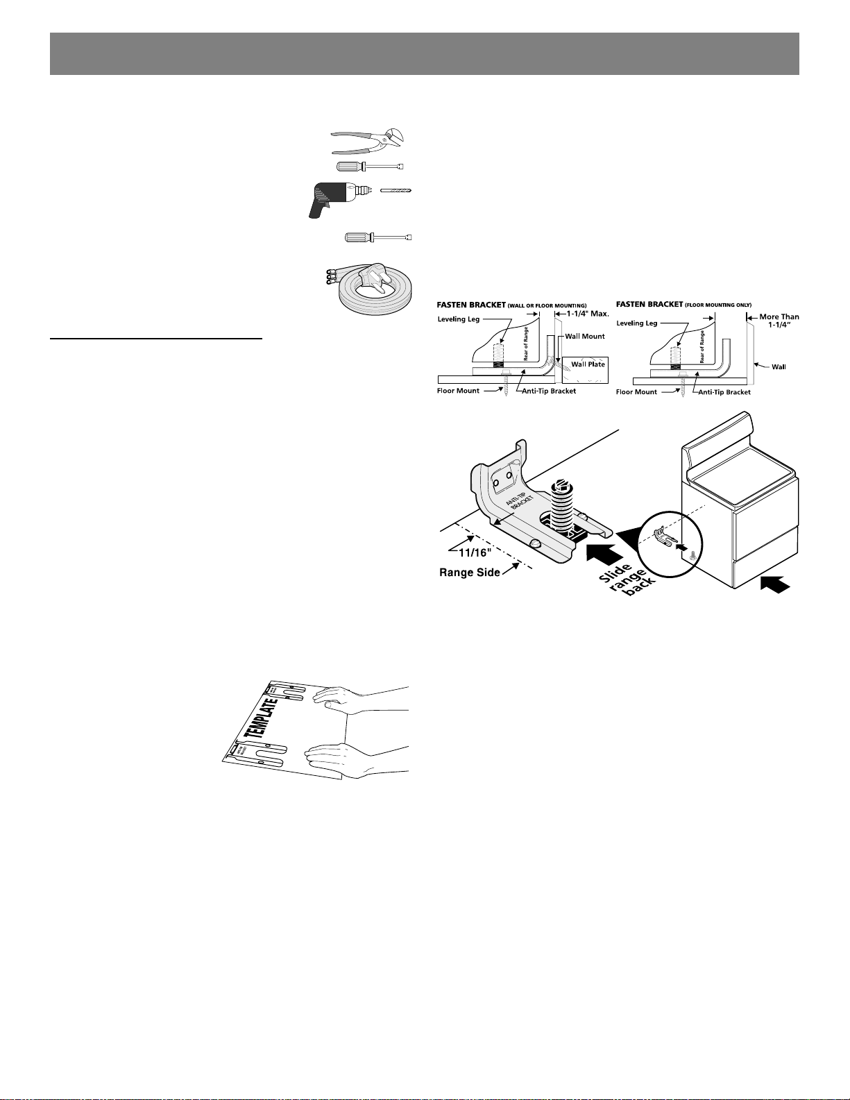
1a. Locate the Bracket using the Template - (Bracket
may be located on either the left or right side of the range. Use
theinformation below tolocate thebracketif templateisnot
2a. Models with Factory Connected Power Supply
Cord. NOTE: Some models may have a factory
installed three (3) conductor Power Supply Cord.
2. ELECTRICAL CONNECTION REQUIREMENTS - This
appliancemustbeproperlyinstalledandgroundedbyaqualified
technicianinaccordancewiththeNationalElectricalCodeANSI/
NFPANo. 70 --latestedition -- andLocal Electrical Code
requirements.
Thisappliancemay be connectedbymeans of "Permanent
Wiring"or "PowerSupplyCord Kit."
WheninstallingPermanent Wiring, do not leaveexcess wire in
range compartment. Excess wire in the range compartment may
notallowthe Rear Access Cover to bereplacedproperly and
couldcreatea potential electricalhazardif wires become pinched.
Connect only as instructed under "Permanent Wire
Connections"in Step 4c. When using flexibleconduitor range
cable use flex connector or range cable strain relief (Fig. 11).
Fig. 4
Fig. 5 Fig. 6
Fig. 7
BEFORESTARTING
Tools You Will Need
For leveling legs and Anti-Tip Bracket:
•Adjustable wrenchor channellock pliers
•5/16"NutdriverorFlatHeadScrewdriver
• Electric Drill & 1/8" Diameter Drill Bit
(MasonryDrillBitifinstallinginconcrete)
For electrical supply connection:
•1/4" &3/8"Socket driveror Nutdriver
AdditionalMaterials YouWillNeed:
• Power Supply Cord or
•Copper ElectricalWiring&MetalConduit
(forhardwiring)
NORMALINSTALLATIONSTEPS
3/16" pilot hole 1-3/4" deep. The screws provided may be used
in wood or concrete material. Use a 5/16" nut-driver or flat
head screwdriver to secure the bracket in place (See Fig. 6).
1c. Level and Position Range - Level range by adjusting
the (4) leveling legs with a wrench. NOTE: A minimum
clearance of 1/8" is required between the bottom of the range
and the leveling leg to allow room for the bracket. Use a spirit
level to check your adjustments. Slide range back into position
(See Fig. 7).
Visuallycheckthatrearlevelinglegisinsertedintoandfully
securedby theAnti-TipBracketbyremoving lowerpanel or
storage drawer. For models with a Warmer Drawer or broiler
compartment,grasp the toprear edgeofthe rangeand carefully
attemptto tilt itforward.
available).
Markthefloororwallwhere
left or right side of the range
willbelocated. If rear of range
is against the wall or no
furtherthan1-1/4"fromwall
wheninstalled,youmayuse
the wall or floor mount
method.Ifmoldingisinstalled
anddoesnot allow the bracket to fitflush against the wall, remove
molding or mount bracket to the floor. For wall mount, locate the
bracketby placing theback edge ofthe templateagainstthe rear
walland the sideedgeof template onthe mark madereferencing
the side of the range (See Fig. 4). Place bracket on top of
template and mark location of the screw holes in wall. If rear of
rangeis further than1-1/4"from the wallwhen installed, attach
brackettothe floor. For floor mount,locate the bracket byplacing
backedgeof the template where therearof the range will be
located. Mark the location of the screw holes, shown in template.
1b. Drill Pilot Holes & Fasten Bracket - Drill a 1/8" pilot
hole where screws are to be located. If bracket is to be mounted
tothewall, drillpilothole atanapproximate20°downwardangle
(SeeFig.5).
If bracket is to be mounted to masonry or ceramic floors, drill a
Mobilehomeinstallations,newbranchcircuitinstallations
(1996NEC)or areaswhereLocal Codesdo not permitgrounding
throughneutral requireafour (4)conductor power supplycord kit
rated at 125/250 volts minimum and marked for use with ranges.
See Range Connection Opening Size Chart (Figs. 9 & 10) for
cordkitampere rating information.Terminalson end ofwires
mustbe either closedloop or open-endspade lugs withupturned
ends.
2
INSTALLATIONINSTRUCTIONSFORFREESTANDINGELECTRICRANGE