manuals.online logo
Brands
  1. Home
  2. •
  3. Brands
  4. •
  5. Frigidaire
  6. •
  7. Range
  8. •
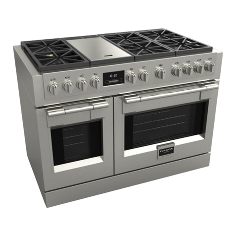
  9. Frigidaire GLGS389ESC User guide

Frigidaire GLGS389ESC User guide

Other Frigidaire Range manuals

Frigidaire GLEF379DBA User manual

Frigidaire

Frigidaire GLEF379DBA User manual

Frigidaire FEFL78C User manual

Frigidaire

Frigidaire FEFL78C User manual

Frigidaire FEF355BF User manual

Frigidaire

Frigidaire FEF355BF User manual

Frigidaire FGGS3045KF - 30' Gas Slide-In Lery SS Group Installation instructions

Frigidaire

Frigidaire FGGS3045KF - 30' Gas Slide-In Lery SS Group Installation instructions

Frigidaire 316901213 User manual

Frigidaire

Frigidaire 316901213 User manual

Frigidaire PLCS389E User manual

Frigidaire

Frigidaire PLCS389E User manual

Frigidaire FGFL77ASE User guide

Frigidaire

Frigidaire FGFL77ASE User guide

Frigidaire FEFD67CHSE User manual

Frigidaire

Frigidaire FEFD67CHSE User manual

Frigidaire GCFI3060BF Owner's manual

Frigidaire

Frigidaire GCFI3060BF Owner's manual

Frigidaire FEF334BGDJ User manual

Frigidaire

Frigidaire FEF334BGDJ User manual

Frigidaire PGLEF385CQ3 User manual

Frigidaire

Frigidaire PGLEF385CQ3 User manual

Frigidaire 318200413 User manual

Frigidaire

Frigidaire 318200413 User manual

Frigidaire FEF339FSE User manual

Frigidaire

Frigidaire FEF339FSE User manual

Frigidaire FEF314A User manual

Frigidaire

Frigidaire FEF314A User manual

Frigidaire PLCF489GC - 40 Inch Dual Fuel Range User manual

Frigidaire

Frigidaire PLCF489GC - 40 Inch Dual Fuel Range User manual

Frigidaire FFES3025LSB Owner's manual

Frigidaire

Frigidaire FFES3025LSB Owner's manual

Frigidaire FFF335ESF User manual

Frigidaire

Frigidaire FFF335ESF User manual

Frigidaire XFGF3005L Owner's manual

Frigidaire

Frigidaire XFGF3005L Owner's manual

Frigidaire FGF375G User manual

Frigidaire

Frigidaire FGF375G User manual

Frigidaire FGF316BSA User manual

Frigidaire

Frigidaire FGF316BSA User manual

Frigidaire PLEF489C User manual

Frigidaire

Frigidaire PLEF489C User manual

Frigidaire Gallery FEF368CJBB User manual

Frigidaire

Frigidaire Gallery FEF368CJBB User manual

Frigidaire GLCS376ABA Installation guide

Frigidaire

Frigidaire GLCS376ABA Installation guide

Frigidaire FGFL87DSC User manual

Frigidaire

Frigidaire FGFL87DSC User manual

Popular Range manuals by other brands

Maytag MGR5875QDW - 30 Inch Gas Range Use and care guide

Maytag

Maytag MGR5875QDW - 30 Inch Gas Range Use and care guide

Capital Precision Series GCR484W Specifications

Capital

Capital Precision Series GCR484W Specifications

Officine Gullo GGS8P Installation and use instruction

Officine Gullo

Officine Gullo GGS8P Installation and use instruction

LG LSD4913 Series owner's manual

LG

LG LSD4913 Series owner's manual

Kenmore 4101 - Elite 30 in. Slide-In Electric Range installation instructions

Kenmore

Kenmore 4101 - Elite 30 in. Slide-In Electric Range installation instructions

Moffat Blue Seal Evolution G576 Technical data sheet

Moffat

Moffat Blue Seal Evolution G576 Technical data sheet

CornuFé C1NF user guide

CornuFé

CornuFé C1NF user guide

GE JGS650SEFSS Dimensions and installation information

GE

GE JGS650SEFSS Dimensions and installation information

LG LDG3015ST Manual De Propietario

LG

LG LDG3015ST Manual De Propietario

Whirlpool RF350PXP Use and care guide

Whirlpool

Whirlpool RF350PXP Use and care guide

Samsung FCQ321HTUW Service manual

Samsung

Samsung FCQ321HTUW Service manual

Kenmore 790.45712 Use & care guide

Kenmore

Kenmore 790.45712 Use & care guide

Wolf CHR CHSSR owner's manual

Wolf

Wolf CHR CHSSR owner's manual

Smeg Built-in Microwave Oven Instructions for the user

Smeg

Smeg Built-in Microwave Oven Instructions for the user

Zanussi ZCG054G user manual

Zanussi

Zanussi ZCG054G user manual

GE JCSS630 quick start guide

GE

GE JCSS630 quick start guide

Samsung NX58M9960P series installation manual

Samsung

Samsung NX58M9960P series installation manual

Hotpoint RB524R Use and care & installation instructions

Hotpoint

Hotpoint RB524R Use and care & installation instructions

manuals.online logo
manuals.online logoBrands
  • About & Mission
  • Contact us
  • Privacy Policy
  • Terms and Conditions

Copyright 2025 Manuals.Online. All Rights Reserved.

1
SERVICE DATA SHEET 318127023 (0505) Rev. A
Gas Slide-in Range with Electronic Oven Control
SAFE SERVICING PRACTICES
To avoid the possibility of personal injury and/or property damage, it is important that safe servicing practices
be observed. The following are examples, but without limitation, of such practices.
1. Do not attempt a product repair if you have any doubts as to your ability to complete it in a safe and
satisfactory manner.
2. Before servicing or moving an appliance, remove power cord from electric outlet, trip circuit breaker to Off,
or remove fuse and turn off gas supply.
3. Never interfere with the proper installation of any safety device.
4. USE ONLY REPLACEMENT PARTS CATALOGED FOR THIS APPLIANCE. SUBSTITUTIONS MAY DEFEAT COMPLIANCE
WITH SAFETY STANDARDS SET FOR HOME APPLIANCES.
5. GROUNDING: The standard color coding for safety ground wires is GREEN OR GREEN WITH YELLOW STRIPES.
Ground leads are not to be used as current carrying conductors. IT IS EXTREMELY IMPORTANT THAT THE
SERVICE TECHNICIAN REESTABLISH ALL SAFETY GROUNDS PRIOR TO COMPLETION OF SERVICE. FAILURE TO
DO SO WILL CREATE A POTENTIAL HAZARD.
6. Prior to returning the product to service, ensure that:
• All electric connections are correct and secure.
• All electrical leads are properly dressed and secured away from sharp edges, high-temperature components,
and moving parts.
• All non-insulated electrical terminals, connectors, heaters, etc. are adequately spaced away from all
metal parts and panels.
• All safety grounds (both internal and external) are correctly and securely reassembled.
• All panels are properly and securely reassembled.
ELECTRONIC OVEN CONTROL
The ES300 electronic oven control is almost identical to the current control with a few exceptions.
Note: The ES300's are not field repairable. Only temperature settings can be changed. See Electronic Oven
Control Guide (section recalibrating your oven temperature).
Note: Depending on model, the size and shape of touch pads may vary (for example round instead of elliptical).
1
P5
15
This service data sheet is intended for use by persons having electrical and mechanical training and a level of
knowledge of these subjects generally considered acceptable in the appliance repair trade. The manufacturer
cannot be responsible, nor assume any liability, for injury or damage of any kind arising from the use of
this data sheet.
NOTICE
Start
time
Bake
time
Timer
On/Off
Clock Bake Broil
Clear
/Off
Controls
Clean
Self-Cleaning Oven
Oven
Preheat
Door Locked
2
1. Shorted keypad.
2. Control's internal checksum may
have become corrupted.
3. Control has sensed a potential
runaway oven condition. Control
may have shorted relay, RTD sensor
probe may have gone bad.
1. Open RTD sensor probe/ wiring
problem. Note: EOC may initially
display an "F1", thinking a runaway
condition exists.
2. Shorted RTD sensor probe / wiring
problem. Note: "F3" is displayed
when oven is in active mode or an
attempt to enter an active mode is
made.
1. Door motor failure / jammed. Latch
motor switch failure.
2. Control software failure, or
component failure (relay stuck).
3. Safety thermostat opened, or cooling
fan stalled.
4. Wiring Problem.
Likely Failure Condition/Cause Suggested Corrective Action
Fault Code
1. Replace EOC.
2. Disconnect power, wait 30 seconds and reapply power.
If fault returns upon power-up, replace EOC.
3. Check RTD sensor probe and replace if necessary. If oven
is overheating, disconnect power. If oven continues to
overheat when the power is reapplied, replace EOC.
Severe overheating may require the entire oven to be
replaced, should damage be extensive.
1. Check wiring in probe circuit for possible open condition.
Check RTD resistance at room temperature (compare to
probe resistance chart). If resistance does not match the
chart, replace the RTD sensor probe.
2. Check wiring in probe circuit for possible short condition.
Check RTD resistance at room temperature (compare to
probe resistance chart). If resistance does not match the
chart, replace the RTD sensor probe.
1. Press CLEAR key.
2. If CLEAR key does not eliminate problem, turn off power
for 30 seconds, then turn on power.
3. Check wiring of Lock Motor, and Lock Switch A and Door
Switch circuits. Look for stalled cooling fan, broken
safety thermostat, shorts or opens.
4. Unplug P4, apply power (L1) directly to the Lock Motor,
if the motor does not rotate, replace Lock Motor Assembly.
Plug P4.
5. Check Lock Switch A for proper operation (do they open
and close, check with ohmmeter). The Lock Motor may
be powered as in above step to open and close Lock
Switch. If the Lock Switch is defective, replace Motor
Lock Assembly.
6. If all above steps fail to correct situation, replace control.
F3
F1
F9
ELECTRONIC OVEN CONTROL FAULT CODE DESCRIPTIONS AND RTD SCALE
ELECTRONIC OVEN CONTROL
During a preheat and/ or normal bake mode, the controller preheats the oven with the bake burner.
During a cleaning process, the oven uses the bake burner. When this mode is called, the door locks right after
start button is pushed.
It is normal to see a temperature overshoot in the
first rise of all modes when you monitor the temperature.
NORMAL BAKE
CLEAN
FIRST RISE
set point
First rise overshoot
T°
t (sec)
3
Oven Temperature
Sensor
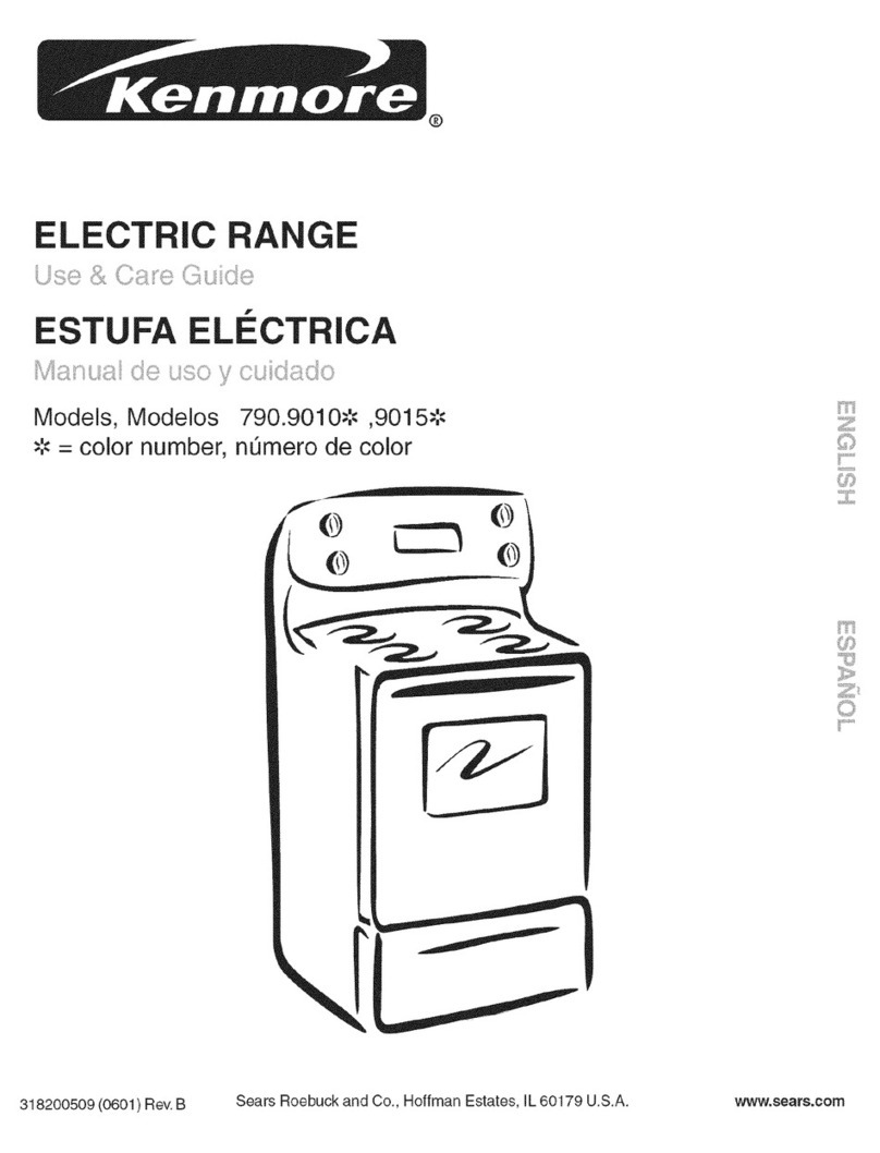
RTD SCALE
Temp. °F Temp. °C Resistance (ohms)
32 ± 1.9 0.0 ± 1.1 1000 ± 4.0
75 ± 2.5 23.9 ± 1.4 1091 ± 5.3
250 ± 4.4 121.1 ± 2.4 1453 ± 8.9
350 ± 5.4 176.7 ± 3.0 1654 ± 10.8
450 ± 6.9 232.2 ± 3.8 1852 ± 13.5
550 ± 8.2 287.8 ± 4.6 2047 ± 15.8
650 ± 9.6 343.3 ± 5.3 2237 ± 18.5
900 ± 13.6 482.2 ± 7.6 2697 ± 24.4
BURNER RATING
Rating See
nameplate
Bake Burner 15 000BTU
Broil Burner 12 000BTU
2 SPEEDS COOLING FAN
A relay and a thermostat (170°/140°) control the speeds of the blower. The high speed should engage in
clean mode only.
CIRCUIT ANALYSIS MATRIX
Bake
P5-1
Broil
P5-2
MDL
P5-6 & N
Lock Motor Switch
A
Bake
Broil
Clean
Unlocked
Locking
Locked
Unlocking
X
X
Cooling Fan
X
X
X
X
X
X
X
X
4
Motor Cooling Fan
Door
Locking
Mechanism
Assembly
Safety
Thermostat
Upper Air Channel
Access Plate
DOOR LOCK MECHANISM
The appliance is equipped with an electronic oven control
and has an auto locking door latch feature. When the self
clean cycle is programmed, the door is locked by a motor
operated latch system. The interior of oven doesn't need to
heat up to 500°F/260°C before the door locks. However, until
the temperature inside oven reaches 500°F/260°C, the self-
clean program can be canceled and door will unlock
immediately. After oven reaches temperatures over 500°F/
260°C, the door will not unlock until temperature drops
below 500°F/260°C.
If a problem appears and the door stays locked it is possible
for the servicer to unlock the door without removing the
appliance from its place. Follow the steps below:
1. Trip the circuit breaker to OFF position.
2. Remove the 2 screws, which are fixing the oven door latch,
located between the control panel and the oven door.
3. When the screws are removed it is possible to unlock the latch with
a flat screwdriver, or one of the tools supplied with the wall oven
which are used to take off the oven from the cabinet. Insert the tool
tip through the slot on top of the oven door. During this step it's
important to take care to not damage the appliance.
4. As soon as the latch is in the unlock position, you can open the door.
5. Replace the motor latch:
1.To have access to the door latch assembly, remove the 3 screws under the control panel which are fixing it.
2.Remove the access plate located on the upper air channel by removing the screw.
3.Replace the motor latch by a new one and reassemble in reverse order.
To Remove the Oven Door:
1. Open the door to the fully opened position.
2. Pull up the lock located on each hinge supports and engage it in the
hinge lever. You may have to apply a little downward pressure on the
door to pull the locks fully over the hooks.
3. Grab the door by the sides, pull the bottom of the door up and toward
you to disengage the hinge supports. Keep pulling the bottom of the
door toward you while rotating the top of the door toward the range to
completely disengage the hinge levers.
OVEN DOOR REMOVAL AND REPLACEMENT
Lock in normal position
Hinge
support
Hinge
lever
HINGE SLOT -Door removed
from the range
Lock engaged for door
removal
To Replace the Oven Door:
1. Grab the door by the sides; place the hinge
supports in the hinge slots. Open the door to
the fully opened position.
2. Disengage the lock from the hinge levers on
both sides.
Note: Make sure the hinge supports are fully
engaged before unlocking the hinge levers.
3. Close the oven door.
The door is heavy. After removing
door, lay it flat on the floor with the inside of the
door facing down.