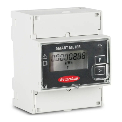
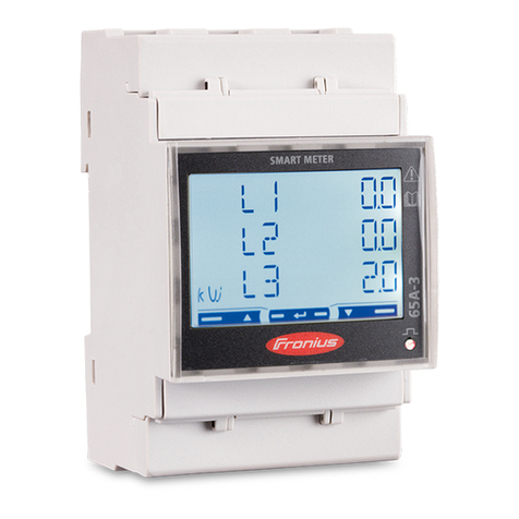
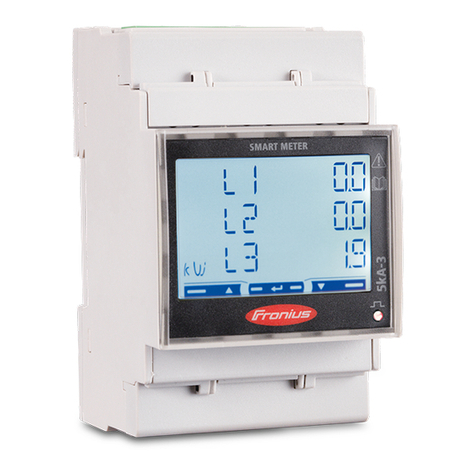
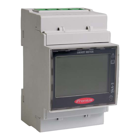
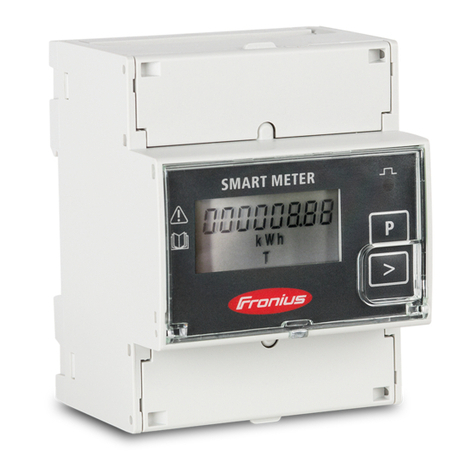
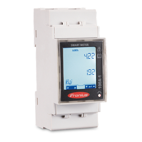
2.3 Connection of external current transducers to the Fronius Smart Meter 50kA-3
The Fronius Smart Meter 50kA-3 is designed for the operation with external current transducers with a
secondary current of 1 A or 5 A. You can select the transducer of your choice, Fronius is not offering
transducers to order! Please note that your selected type has to be in line with the selection criteria outlined in
the document “Selection criteria for a current converter for the Fronius Smart Meter 50kA-3”
http://www.fronius.com/cps/rde/xbcr/SID-C3A503DB-
9EB48230/fronius_international/SE_IS_Selection_criteria_for_current_converter_EN_735004_snapshot.pdf
One of the most important things is the right order of the cable connection from the current transducer to the
Fronius Smart Meter. They have on the primary “P” side an inlet market “P1” and an outlet marked “P2”. Make
sure that you wire the phase cable in the direction from “P1” to “P2” through the aperture. Also, connect the
cables from the current converters secondary connectors “S1” and “S2” to the Fronius Smart Meter in the right
order as shown in graphic 5.
Current transducer on phase “L1”: “S1” to connector “1”; “S2” to connector “3”.
Current transducer on phase “L2”: “S1” to connector “4”; “S2” to connector “6”.
Current transducer on phase “L1”: “S1” to connector “7”; “S2” to connector “9”.
Additionally, there is the possibility to connect a grounding cable to the external current transducers, if required.
Graphic 5: Overview of cable connections to Fronius Smart Meter 50kA-3
When connecting the cables for voltage measurement to the bottom terminal on clamps “2”, “5”, and “8”, please
make sure that each of them is fused with 6 Amp fuses. Neutral can be connected on clamp “11”.
For communication connect the CAT5 / CAT6 twisted pair cables on “D+” “33”, “D –“ “34” and “–“ “35”.
Don’t forget the termination as described in 2.2 above.
2.4 Programming the transmission ratio into the Fronius Smart Meter.
After you have done the commissioning of the Fronius Smart Meter it is mandatory to program the transmission
ratio into the Fronius Smart Meter. Depending on the transmission ratio, indicated in the tech specs of the
current converter, this factor has to be set into the software of the Fronius Smart Meter in order to display the
correct values.
In the example shown in graphic 5, the factors on the primary side is “50” and on the secondary side is “5”. You
can calculate the configuration factor very easy by just dividing the primary value through the secondary value,
