manuals.online logo
Brands
  1. Home
  2. •
  3. Brands
  4. •
  5. FRO­NIUS
  6. •
  7. Measuring Instrument
  8. •
  9. FRO­NIUS 63A-1 User manual

FRO­NIUS 63A-1 User manual

(c) Fronius Australia Pty. Ltd, 2015 1/10
Quick guide:
How to do install a Fronius Smart Meter*
*Single phase or 3-phase Energy Meter
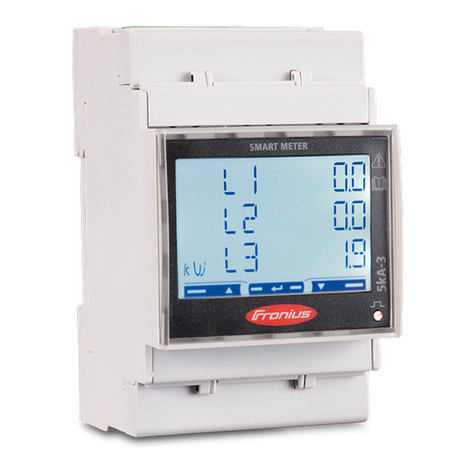
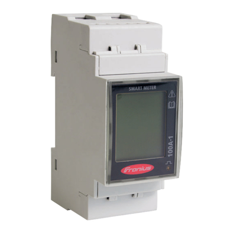
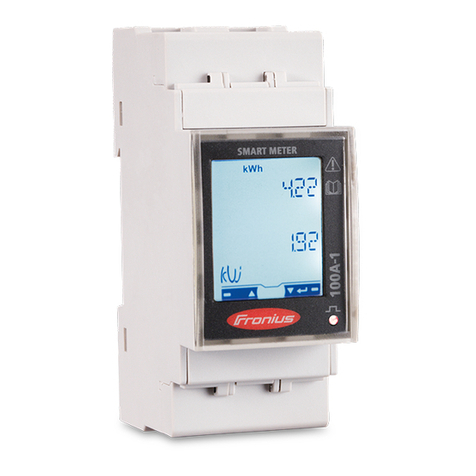
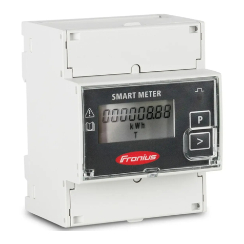
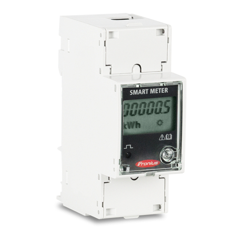
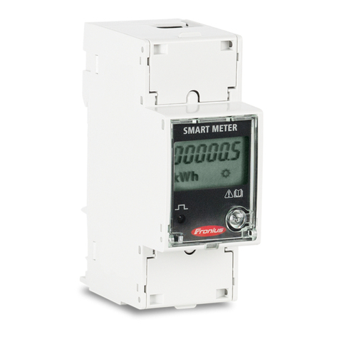
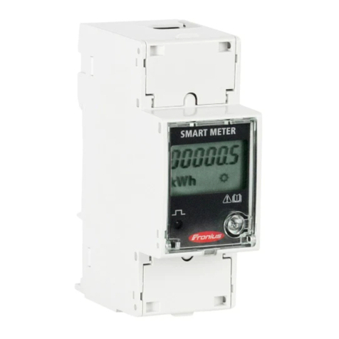
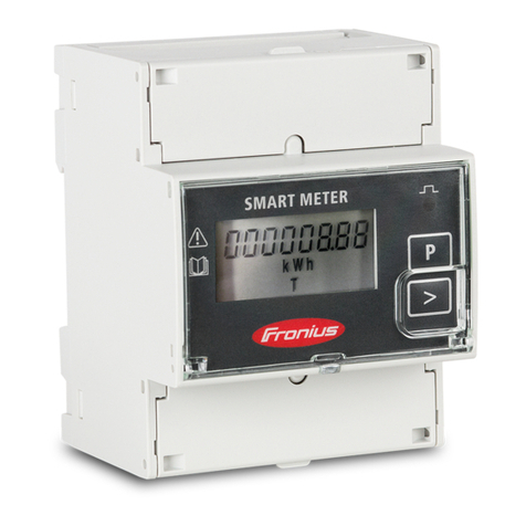
43,0001,1477 Fronius Smart Meter 63A-1
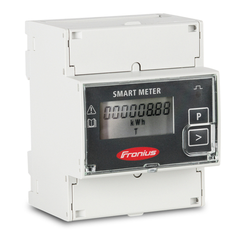
43,0001,1473 Fronius Smart Meter 63A-3
(c) Fronius Australia Pty. Ltd, 2015 2/10
White Paper
© Fronius Australia Pty Ltd., VH
Version 1.0/2015
Fronius reserves all rights, in particular rights of reproduction, distribution and translation.
No part of this work may be reproduced in any way without the written consent of Fronius. It must not be saved, edited,
reproduced or distributed using any electrical or electronic system.
You are hereby reminded that the information published in this document, despite exercising the greatest of care in its
preparation, is subject to change and that neither the author nor Fronius can accept any legal liability
Gender-specific wording refers equally to female and male form.
(c) Fronius Australia Pty. Ltd, 2015 3/10
1 GENERAL
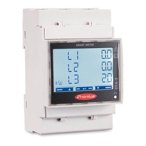
Fronius Smart Meters (single phase or 3-phase) are energy meters that work in conjunction with the Fronius
Datamanager V2. The Smart Meter must be connected to the Fronius Datamanager V2 which comes built-in to
all Fronius SnapINverters (Galvo, Primo, Symo and Eco), and can be retrofitted into all other Fronius inverters.
Using a ModBus RTU / RS 485 connection protocol, the smart meter can be utilised to monitor consumption
data or in order to limit the export of a PV system. They can measure current/voltage/energy/reactive
power/apparent power in total or per line.
Once a battery is added to an installation a Smart Meter is mandatory. If the installation is single or dual phase
a 3-phase Smart Meter can be used.
This document describes how to do install and setup the Fronius Smart Meter.
1.1 Requirements
/ Important! The Fronius Smart Meter cannot be used in combination with the Fronius Datamanager Version 1.
/ The Fronius Datamanager V2 needs to have a software version of V3.3.6-13 or greater. (For details how to
upgrade the firmware see chapter 1.3 Software update of Fronius Datamanager).
/ The Datamanager needs to be set up before executing the meter settings. For information on how to set up
the Fronius Datamanager please see the Fronius inverter or the Fronius Datamanager manual (for Fronius
Galvo/Symo/Primo/Eco):
http://www.fronius.com/cps/rde/xbcr/SID-DBD64F5C-
18F6818F/fronius_australia/42_0426_0191_EA_388899_snapshot.pdf
1.2 Where to put the Fronius Smart Meter
Due to the setup of installations in Australia, in most cases the meter will be put into the feed-in path (diagram
1). If the PV system is connected to a sub board it’s most likely to achieve the load measurement by having the
meter in the feed-in path. In rare occasion it can be put into the consumption path (diagram 2).
/ Feed-in point
In this setting the solar generation passes through the meter as well as the site load.
(Diagram 1)
Loads
Grid
Fronius
Smart Meter
Loads
PV System
Site
main
switch
(c) Fronius Australia Pty. Ltd, 2015 4/10
/ Consumption path
The meter in this scenario does not measure the solar production, only the consumption.
(Diagram 2)
1.3 Software update for Fronius Datamanager
The easiest way to update the Fronius Datamanager is to use the Datamanager’s web interface. To update
your software access the web interface follow the steps below:
/ Activate the Wi-Fi hotspot on the Datamanager card (inverter) or Datamanager Box V2
/ Connect your computer/tablet/smart phone to the Datamanager’s WLAN hotspot
/ Open a web browser and go to http://192.168.250.181 or http://datamanager/
Alternatively you can use Fronius SolarWeb App for tablet or smart phone and go to ‘Settings’ and click
‘PV Inverter Homepage’
/ Select Firmware update The Datamanager web interface (PV Inverter Homepage)
Go to ‘Firmware update’’
Grid
Fronius
Smart Meter
PV System
Loads
Loads
Site
main
switch
(c) Fronius Australia Pty. Ltd, 2015 5/10
/ Check and run update on the firmware update page
/ Start the download
/ The software will automatically download
Check whether a newer
software is available.
Start the update procedure.
Read through the information
and click ‘Yes’
Select ‘Update via Web’if internet connection is
available (recommended)
Select ‘Update via LAN’ if the update file is
stored locally on the computer*.
(c) Fronius Australia Pty. Ltd, 2015 6/10
/ To finish the update klick OK
For more detailed information on how to upgrade the firmware for Fronius Datamanager V2 please see the
Operating Instructions on the Fronius website under Solar Energy / Products / System monitoring / Datalogging
/Fronius Datamanager 2.0 or click: http://www.fronius.com/cps/rde/xbcr/SID-DBD64F5C-
18F6818F/fronius_australia/42_0426_0191_EA_388899_snapshot.pdf
*In case there is no internet connection on the Datamanager the software update can be done via a computer.
The software can be downloaded from the Fronius Website under Solar Energy/Info & Support/Software
Downloads/Software Updates or click here: http://www.fronius.com/cps/rde/xchg/SID-1CE5A97E-
8EC72008/fronius_australia/hs.xsl/25_7671.htm
(c) Fronius Australia Pty. Ltd, 2015 7/10
2 INSTALLATION AND SETUP OF THE FRONIUS SMART METER
2.1 Schematics and Wiring
Diagram 3 shows the system configuration
(Diagram 3)
Please note:
/ Wiring between meter and inverter should use CAT5 or CAT6 cable (LAN cable)
/ Connection is a data line for Modbus RTU / RS485 using screw terminals on the meter
/ Maximum distance: 300 m (980 feet)
Meter connection on the Datamanager V2
The meter needs to be connected to the Datamanager’s binary output, as shown in diagram 4.
(Diagram 4)
L1
N
ModBus RTU / RS485
Fronius inverter with
Datamanager V2
Fronius Smart Meter
(c) Fronius Australia Pty. Ltd, 2015 8/10
Wiring detail for 3-Phase Smart Meter 63A/3PH and Datamanager V2
(Diagram 5)
Wiring detail for Single Phase Smart Meter 63A/1PH*** and Fronius Datamanager V2
(Diagram 6)
Modbus termination switch on the Datamanager
The internal bus termination 120-Ohm resistance (for Modbus RTU) needs to
be switched to ON to be activated.
Please Note:
The termination resistance must be activated for the first and last device in an
RS-485 bus.
* The 120 Ohm terminating
resistor comes with the meter
*** Please note that the
connections 33, 34, 35 on the
Fronius Smart Meter are in
reverse order to those shown
in diagram 6!
* The 120 Ohm terminating
resistor comes with the
meter
** It is important to connect
the Neutral.
(c) Fronius Australia Pty. Ltd, 2015 9/10
2.2 Activate the meter on the Fronius Datamanager web interface
The dynamic power reduction can be set on the web interface of the Fronius Datamanager as shown below.
/ On the Datamanager web interface select Settings
/ Before it is possible to enter the METER settings a service password is required. If no service password has
been set, it needs to be created first!
Go to ‘METER’ to do the
relevant settings.
Important! If no service
password has been set:
Choose a service password
under PASSWORDS.
Go to ‘Settings’.
(c) Fronius Australia Pty. Ltd, 2015 10/10
/ Choose the type of meter.
/ Choose the installation location.
For further explanations on feed-in path and consumption path see chapter 1.2 Where to put the Fronius Smart
Meter
/ The meter is activated once you get the following message. Click OK!
Done!
For more information on the Fronius Datamanager V2 please see the Operating Instructions on the Fronius
website under Solar Energy / Products / System monitoring / Datalogging /Fronius Datamanager 2.0
or click: http://www.fronius.com/cps/rde/xbcr/SID-DBD64F5C-
18F6818F/fronius_australia/42_0426_0191_EA_388899_snapshot.pdf
Select ‘Fronius Smart Meter’
Select whether the meter is
located in the feed-in path or in
the consumption path
Save the setting by
clicking the tick!

Other manuals for 63A-1

5

This manual suits for next models

1

Other FRO­NIUS Measuring Instrument manuals

FRO­NIUS Smart Meter 240V-3 UL User manual

FRO­NIUS

FRO­NIUS Smart Meter 240V-3 UL User manual

FRO­NIUS Smart Meter 50kA-3 User manual

FRO­NIUS

FRO­NIUS Smart Meter 50kA-3 User manual

FRO­NIUS String Control 100/12 MET User manual

FRO­NIUS

FRO­NIUS String Control 100/12 MET User manual

FRO­NIUS TS 5kA-3 User manual

FRO­NIUS

FRO­NIUS TS 5kA-3 User manual

FRO­NIUS Smart Meter 50kA-3 User manual

FRO­NIUS

FRO­NIUS Smart Meter 50kA-3 User manual

FRO­NIUS TS 5kA-3 User manual

FRO­NIUS

FRO­NIUS TS 5kA-3 User manual

FRO­NIUS 63A-1 User manual

FRO­NIUS

FRO­NIUS 63A-1 User manual

FRO­NIUS RI FB PRO/i User manual

FRO­NIUS

FRO­NIUS RI FB PRO/i User manual

FRO­NIUS Smart Meter 240-3 UL User manual

FRO­NIUS

FRO­NIUS Smart Meter 240-3 UL User manual

FRO­NIUS 63A-3 User manual

FRO­NIUS

FRO­NIUS 63A-3 User manual

FRO­NIUS 63A-1 User manual

FRO­NIUS

FRO­NIUS 63A-1 User manual

FRO­NIUS Smart Meter TS 100A-1 User manual

FRO­NIUS

FRO­NIUS Smart Meter TS 100A-1 User manual

FRO­NIUS Smart Meter IP User manual

FRO­NIUS

FRO­NIUS Smart Meter IP User manual

FRO­NIUS Smart Meter IP User manual

FRO­NIUS

FRO­NIUS Smart Meter IP User manual

FRO­NIUS 63A-1 User manual

FRO­NIUS

FRO­NIUS 63A-1 User manual

FRO­NIUS Smart Meter 50kA-3 User manual

FRO­NIUS

FRO­NIUS Smart Meter 50kA-3 User manual

FRO­NIUS LaserHybrid WF 25i User manual

FRO­NIUS

FRO­NIUS LaserHybrid WF 25i User manual

FRO­NIUS WR User manual

FRO­NIUS

FRO­NIUS WR User manual

FRO­NIUS 63A-3 User manual

FRO­NIUS

FRO­NIUS 63A-3 User manual

FRO­NIUS Smart Meter 240V-3 UL User manual

FRO­NIUS

FRO­NIUS Smart Meter 240V-3 UL User manual

FRO­NIUS TS 5kA-3 User manual

FRO­NIUS

FRO­NIUS TS 5kA-3 User manual

FRO­NIUS 63A-1 User manual

FRO­NIUS

FRO­NIUS 63A-1 User manual

FRO­NIUS 63A-3 User manual

FRO­NIUS

FRO­NIUS 63A-3 User manual

FRO­NIUS Smart Meter TS 65A-3 User manual

FRO­NIUS

FRO­NIUS Smart Meter TS 65A-3 User manual

Popular Measuring Instrument manuals by other brands

PRO-TEK WI Series user manual

PRO-TEK

PRO-TEK WI Series user manual

A/DA COSMO 40 operating manual

A/DA

A/DA COSMO 40 operating manual

Metrol RC Series instruction manual

Metrol

Metrol RC Series instruction manual

Alfalaval TE67X000002029 instruction manual

Alfalaval

Alfalaval TE67X000002029 instruction manual

Microtech e-DIAGNOSTIC quick start guide

Microtech

Microtech e-DIAGNOSTIC quick start guide

In-situ Partech 228531 Operator's manual

In-situ

In-situ Partech 228531 Operator's manual

Check-line TI-CMXDL operating manual

Check-line

Check-line TI-CMXDL operating manual

JB Systems Light TWINBEAM COLOR Operation manual

JB Systems Light

JB Systems Light TWINBEAM COLOR Operation manual

Digi-Sense 20250-65 user manual

Digi-Sense

Digi-Sense 20250-65 user manual

Sel BOX BASIC RI 3000 EtherNet/IP instruction manual

Sel

Sel BOX BASIC RI 3000 EtherNet/IP instruction manual

Check-line StroboVision SMS-400B Operation manual

Check-line

Check-line StroboVision SMS-400B Operation manual

Unit UT181A operating manual

Unit

Unit UT181A operating manual

Lake Shore 340 installation instructions

Lake Shore

Lake Shore 340 installation instructions

AutomationDirect ProSense DPM2 Series user manual

AutomationDirect

AutomationDirect ProSense DPM2 Series user manual

B+K precision 885 instruction manual

B+K precision

B+K precision 885 instruction manual

Delta HD2105.2 operating manual

Delta

Delta HD2105.2 operating manual

Skywatch ATMOS user manual

Skywatch

Skywatch ATMOS user manual

Delta OHM HD2070 manual

Delta OHM

Delta OHM HD2070 manual

manuals.online logo
manuals.online logoBrands
  • About & Mission
  • Contact us
  • Privacy Policy
  • Terms and Conditions

Copyright 2025 Manuals.Online. All Rights Reserved.