2
Allgemeines
Sicherheit
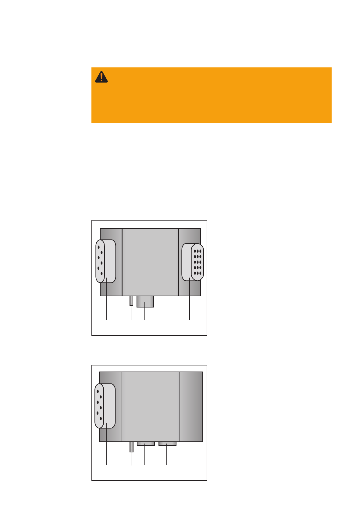
(4)
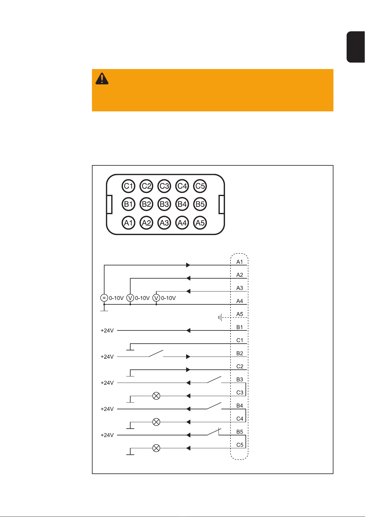
Abb. 1 Anschlüsse Interface „Harting“
(3) (2) (1)
(1) Stecker Steuersignale ... zum
Anbinden der Schnittstelle an die
Robotersteuerung
(2) Stecker LocalNet ... standardisierte
Anschlußbuchse für Systemerweite-
rungen (z.B. Fernbedienung, etc.)
(3) Schutzleiterkontakt ... zum Anschlie-
ßen zusätzlicher Optionen an den
Schutzleiter der Stromquelle (z.B.
Fahrwagen, Lichtbogenabschaltbox,
etc.)
(4) Stecker Netzkabel ... zum Anschlie-
ßen der Stromquelle an das Strom-
netz
Das Interface DPS 2500 analog ist eine Schnittstelle zum Anbinden der Plasmastrom-
quelle DPS 2500 an eine Robotersteuerung. Es stehen 2 Ausführungen zur Verfügung:
- Interface DPS 2500 analog mit Stecker „Harting“
- Interface DPS 2500 analog mit Stecker „Binder“
Die beiden Ausführungen unterscheiden sich durch unterschiedliche Stecker zur Anbin-
dung an die Robotersteuerung.
Gerätekonzept
Warnung! Fehlbedienung kann schwerwiegende Personen- und Sachschäden
verursachen. Die angeführten Tätigkeiten erst durchführen, wenn diese Bedie-
nungsanleitung und folgende Dokumente vollständig gelesen und verstanden
wurden:
- Die Bedienungsanleitung der Stromquellle, insbesondere das Kapitel
„Sicherheitsvorschriften“.
- Sämtliche Bedienungsanleitungen der gesamten Anlage
(4)
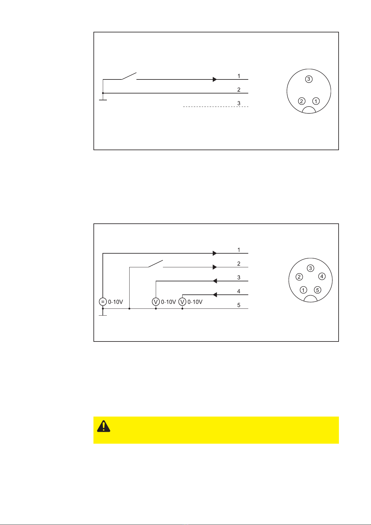
Abb. 2 Anschlüsse Interface „Binder“
(3) (2) (1)
(1) Stecker Schnellabschaltung ... zum
Anbinden der Schnittstelle an die
Robotersteuerung
(2) Stecker Steuersignale ... zum
Anbinden der Schnittstelle an die
Robotersteuerung
(3) Schutzleiterkontakt ... zum Anschlie-
ßen zusätzlicher Optionen an den
Schutzleiter der Stromquelle (z.B.
Fahrwagen, Lichtbogenabschaltbox,
etc.)
(4) Stecker Netzkabel ... zum Anschlie-
ßen der Stromquelle an das Strom-
netz
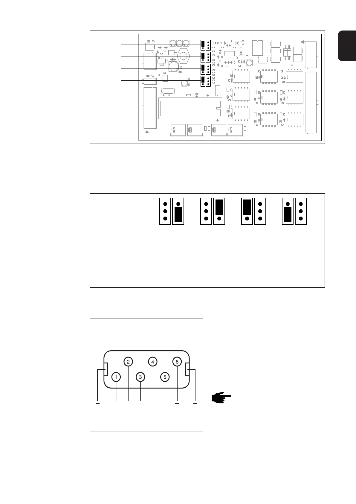
Interface mit
Stecker „Harting“
Interface mit
Stecker „Binder“