Frontier SKYTRAQ VENUS 838 User manual

Low cost receiver
Prototype
pg. 1 Low-Cost SBAS Receiver Design (SkyTraq Venus 838) - 25/02/2020
This document describes Open Hardware and is licensed under the CERN OHL v. 1.2.
You may redistribute and modify this documentation under the terms of the CERN OHL v. 1.2. (http://ohwr.org/cernohl)
This documentation is distributed WITHOUT ANY EXPRESS OR IMPLIED WARRANTY, INCLUDING MERCHANTABILITY, SATISFACTORY QUALITY AND
FITNESS FOR A PARTICULAR PURPOSE. Please see the CERN OHL v. 1.2 for applicable conditions
LOW-COST SBAS RECEIVER DESIGN
(SKYTRAQ VENUS 838)
Table of Contents
1. COMPONENTS .................................................................................................................................................2
2. REQUIRED EQUIPMENT....................................................................................................................................2
3. BUILD PROCEDURE..........................................................................................................................................2
3.1. 3D Printing the Enclosure ......................................................................................................................................................... 2
3.1.1. Main Enclosure ............................................................................................................................................................... 2
3.1.2. Enclosure Lid .................................................................................................................................................................. 3
3.1.3. Charger Tray .................................................................................................................................................................. 3
3.2. Preparing the Components ....................................................................................................................................................... 3
3.2.1. Attaching Headers to the SkyTraq Venus 838 Evaluation Board.......................................................................................... 3
3.2.2. Preparing the Adafruit PowerBoost 1000 .......................................................................................................................... 4
3.3. Assembling the Components ..................................................................................................................................................... 4
3.3.1. Power Assembly.............................................................................................................................................................. 4
3.3.2. HC-06 Connection ........................................................................................................................................................... 5
3.4. Configuring the SkyTraq output baudrate .................................................................................................................................. 5
3.5. Enabling SBAS on the SkyTraq .................................................................................................................................................. 6
3.6. Installing the Components into the Enclosure............................................................................................................................. 6
4. SETUP AND OPERATION...................................................................................................................................8
5. TROUBLESHOOTING ........................................................................................................................................8
6. CONTACT INFORMATION .................................................................................................................................8

Low cost receiver
Prototype
pg. 2 Low-Cost SBAS Receiver Design (SkyTraq Venus 838) - 25/02/2020
This document describes Open Hardware and is licensed under the CERN OHL v. 1.2.
You may redistribute and modify this documentation under the terms of the CERN OHL v. 1.2. (http://ohwr.org/cernohl)
This documentation is distributed WITHOUT ANY EXPRESS OR IMPLIED WARRANTY, INCLUDING MERCHANTABILITY, SATISFACTORY QUALITY AND
FITNESS FOR A PARTICULAR PURPOSE. Please see the CERN OHL v. 1.2 for applicable conditions
1. Components
To build your own SkyTraq Venus 838 based SBAS-capable receiver with on-board power and Bluetooth connectivity, you will
require the following main components:
SkyTraq Venus 838 SBAS Receiver
Component
Approximate Cost (AUD)
SkyTraq Venus 838FLPx Evaluation Kit
$110.00
Adafruit PowerBoost 1000c Charger Board
$36.67
3.7V 2400mAh LiPo Battery
$19.95
HC-06 Bluetooth Module
$10.00
Total
$176.62
In addition to these main components, you will need the following electronics components:
•Jumper Wires (x4)
•Toggle Switch
•2.54mm Breakaway Male Header (x4 minimum)
•Adhesive tape (thin, double-sided)
FrontierSI claims no affiliation with the creators and distributors of any of these components. These were selected for their
availability and relatively low-cost. Alterations on this design may function with alternative components, but the enclosures
have been dimensioned with these in mind.
2. Required Equipment
You will require the following equipment and the skills necessary for their safe operation.
•3D Printer
•Soldering Iron
•Fine-tooth file
3. Build Procedure
3.1.3D Printing the Enclosure
The first step is to 3D print a suitably sized enclosure using the provided .STL files. If you do not have access to your own 3D
printer, consider visiting your local Makerspace, University, or purchasing a printed part from a reputable 3D printing service.
There are 3 components to print, listed below:
3.1.1. Main Enclosure
This is the most complex part of the 3D printed
assembly, which houses all the assembled components.
There are separate shelves for the Battery and Bluetooth
module, and dimensioned rails to house the charger
board tray, and the SkyTraq Venus 838 Evaluation Kit.
This item should be printed in the shown orientation,
with the baseplate containing the holes for the switch,
SMA antenna connector, and the charger board at the
bottom. Depending on your 3D printer and settings, this
will take around 4 hours to produce.

Low cost receiver
Prototype
pg. 3 Low-Cost SBAS Receiver Design (SkyTraq Venus 838) - 25/02/2020
This document describes Open Hardware and is licensed under the CERN OHL v. 1.2.
You may redistribute and modify this documentation under the terms of the CERN OHL v. 1.2. (http://ohwr.org/cernohl)
This documentation is distributed WITHOUT ANY EXPRESS OR IMPLIED WARRANTY, INCLUDING MERCHANTABILITY, SATISFACTORY QUALITY AND
FITNESS FOR A PARTICULAR PURPOSE. Please see the CERN OHL v. 1.2 for applicable conditions
The printing process and final product are shown below:
3.1.2. Enclosure Lid
The enclosure lid is designed with a tapered lip to allow a press-fit onto the outside of the
main enclosure. The tapered section may cause some issues if your 3d printer is not
correctly calibrated, as the walls become quite thin near the top. Depending on your 3D
printer and settings, this will take around 2-3 hours to produce. Please note that some
scaffolding may be required for the external labels to print correctly.
3.1.3. Charger Tray
This tray is dimensioned to fit the Adafruit PowerBoost 1000 Charger Board. Once
assembled, both this tray and the board will hang upside-down from the rail in the Main
Enclosure, with the USB port exposed externally to allow easy recharging. Depending on
your 3D printer and settings, this will take less than 1 hour to produce.
3.2.Preparing the Components
3.2.1. Attaching Headers to the SkyTraq Venus 838 Evaluation Board
To allow the SkyTraq board to communicate via Bluetooth, it will require 4 header pins to be soldered onto the board. This is
easiest to achieve using a strip of breakaway headers. It is possible to connect only the pins that you will need, but this
increases the chance of damaging the connections due to decreased rigidity. Connecting the whole strip of breakaway
headers will also allow further flexibility if you choose to explore other functions of the board. As you can see in the figure
below, and in the attached SkyTraq Venus 838 schematic, the pins that we will need for this project will be number 2 (Power
for Bluetooth), number 8 (Ground for Bluetooth), and numbers 16 & 18 for Bluetooth Tx and Rx respectively.

Low cost receiver
Prototype
pg. 4 Low-Cost SBAS Receiver Design (SkyTraq Venus 838) - 25/02/2020
This document describes Open Hardware and is licensed under the CERN OHL v. 1.2.
You may redistribute and modify this documentation under the terms of the CERN OHL v. 1.2. (http://ohwr.org/cernohl)
This documentation is distributed WITHOUT ANY EXPRESS OR IMPLIED WARRANTY, INCLUDING MERCHANTABILITY, SATISFACTORY QUALITY AND
FITNESS FOR A PARTICULAR PURPOSE. Please see the CERN OHL v. 1.2 for applicable conditions
3.2.2. Preparing the Adafruit PowerBoost 1000
The Adafruit PowerBoost 1000 comes with a loose USB A jack. The USB A jack must be soldered onto the PowerBoost board,
as this will be the main method by which the SkyTraq Venus 838 Evaluation board will be powered. There are two pins that
must have headers soldered on (similarly to the previous step) to allow a Toggle switch to be attached, which will act as the
Receiver on/off switch. These are labelled “EN” and “GND”, as shown in the picture below:
3.3.Assembling the Components
3.3.1. Power Assembly
The Adafruit PowerBoost 1000 should now have all the
connections necessary to construct the assembly shown in
the image to the left. The toggle switch should be connected
to the header pins labelled “EN” and “GND”. From there, the
2400 mAh LiPo can be connected using the attached plug.
If this assembly is working correctly, the switch should turn
the board on and off, which will be visible via the power and
charge level lights on the PowerBoost 1000. When the
switch is in the on position, the USB A port should now be
able to power the SkyTraq Venus 838 evaluation board via
its MiniUSB port. It is advisable to find a USB Type A to
MiniUSB cable that is as short as possible, as the cable will
need to bundled up to remain inside the enclosure when the
Lid is on.
Please note that the battery can now be charged via the
MicroUSB port, and the current charge status will be
indicated by a coloured LED on the PowerBoost 1000 board.
Next, take the charger tray that you 3D printed, and fit the
posts through the holes on the MicroUSB end of the PowerBoost. If they do not clear fully, use sandpaper or a fine-tooth file
to re-shape the posts until they fit. A snug or tight fit is preferable, as the board will be hung upside-down. Once the board
fits, you may put down some double-sided tape around the outside of the charger tray and gently squeeze the assembly
together.

Low cost receiver
Prototype
pg. 5 Low-Cost SBAS Receiver Design (SkyTraq Venus 838) - 25/02/2020
This document describes Open Hardware and is licensed under the CERN OHL v. 1.2.
You may redistribute and modify this documentation under the terms of the CERN OHL v. 1.2. (http://ohwr.org/cernohl)
This documentation is distributed WITHOUT ANY EXPRESS OR IMPLIED WARRANTY, INCLUDING MERCHANTABILITY, SATISFACTORY QUALITY AND
FITNESS FOR A PARTICULAR PURPOSE. Please see the CERN OHL v. 1.2 for applicable conditions
3.3.2. HC-06 Connection
The SkyTraq Evaluation board can now be
connected to the HC-06 Bluetooth module via the
header pins. As you can see in the diagram to the
left, there are 4 jumper wires connecting these two
components.
The components should be connected as follows:
•SkyTraq Pin 2 -> HC-06 VCC
•SkyTraq Pin 8 -> HC-06 GND
•SkyTraq Pin 16 (RX) -> HC-06 TXD
•SkyTraq Pin 18 (TX) -> HC-06 RXD
Try and ensure that these connections are stable
and will not pull themselves free under vibrations
from regular use.
You should now be able to plug the USB A from the
Adafruit PowerBoost 1000 into the MiniUSB on the
SkyTraq Venus 838 board. Toggling the switch
should cause the LEDs on the SkyTraq to illuminate.
The next step is to allow the SkyTraq and HC-06 to
communicate.
3.4.Configuring the SkyTraq output baudrate
The HC-06 Bluetooth module comes with a default baudrate of 9600. To function correctly, both the HC-06 and the SkyTraq
must be set to the same baudrate. It is a much simpler task to alter the baudrate of the SkyTraq than the HC-06, so that is
the recommended method.
To alter the SkyTraq baudrate, you will need to download some drivers and an application to a PC.
You can find the USB drivers here:
https://www.silabs.com/products/development-tools/software/usb-to-uart-bridge-vcp-drivers
And you can find the configuration software / data viewer here:
http://navspark.mybigcommerce.com/content/GNSS_Viewer.zip
Once you have installed both of these, it is advisable to restart your PC.
Once restarted, try connecting the SkyTraq directly via USB to the PC, with the HC-06 module RX and TX disconnected from
the SkyTraq header pins. Having these pins connected can cause issues when attempting to interface with the board until
the baudrates are matched. You should see the SkyTraq appear in the ports (COM & LPT) section of Device Manager. Note
the COM port number that this is connected to. If you are unsure about which device is the SkyTraq, try disconnecting and
reconnecting the device, and note which device appears in Device Manager.
Once you have opened GNSS Viewer, you will find a section in the Top-Left corner with a drop-down list for COM ports, and
a drop-down for baudrate next to it. If you are unsure about either of these values, the software has a feature to Scan Port
or Scan Baud, which will iterate through until it finds the correct port and baudrate. If you know the COM port number, enter
that here, and press the “Close” button to open the connection. If this has connected properly, you will see some data in the
“Message” and “Response” sections of GNSS Viewer. Now navigate to the “Binary” drop-down menu and select “Configure

Low cost receiver
Prototype
pg. 6 Low-Cost SBAS Receiver Design (SkyTraq Venus 838) - 25/02/2020
This document describes Open Hardware and is licensed under the CERN OHL v. 1.2.
You may redistribute and modify this documentation under the terms of the CERN OHL v. 1.2. (http://ohwr.org/cernohl)
This documentation is distributed WITHOUT ANY EXPRESS OR IMPLIED WARRANTY, INCLUDING MERCHANTABILITY, SATISFACTORY QUALITY AND
FITNESS FOR A PARTICULAR PURPOSE. Please see the CERN OHL v. 1.2 for applicable conditions
Serial Port”. A window should appear, in which you can set the output baudrate to 9600. Save this configuration, and then
disconnect by pressing the “Close” button again. You can then try connecting to the SkyTraq board in the exact same
manner on the same COM port, but with a baud rate of 9600 this time. If GNSS viewer then behaves regularly, you can now
configure the other settings to suit your use case and environment.
3.5.Enabling SBAS on the SkyTraq
To allow the SkyTraq to use the Australia and New Zealand SBAS, you
need to use the “Configure SBAS Advance” item from the “Venus 8”
Drop-down menu in GNSS Viewer.
Once you can see a form similar to the one displayed here on the left,
you should enable the SBAS system, disable Ranging, enable the
corrections, and then enable WAAS. From there, use the “Modify
Default PRN” section to change the WAAS PRN to 122, the PRN of the
Australia and New Zealand SBAS.
You can now save the configuration.
It is also recommended to disable position pinning to allow true 1hz (or
higher) output rates, and to change the Navigation mode to suit your
use case kinematics. In our testing we have found the navigation mode
to have a significant impact on the positioning performance.
You should set the NMEA output to suit your requirements, generally
$GPGGA strings are the most useful, as they contain your location.
You can now re-connect the HC-06 Bluetooth module.
3.6.Installing the Components into the Enclosure
At this stage you should have two functioning assemblies: the SkyTraq board with attached HC-06 Bluetooth module, and
the Adafruit PowerBoost board mounted to the 3D-printed tray with attached battery and switch. The next step is to place all
of these components into the Enclosure. Images of the complete power assembly and the compartments/through-holes for
each of the components in main enclosure are shown below:
Please note that the solder connections to the battery may be fragile; take care not to force any of the components into their
compartments, and to stop if anything feels too tight in order to avoid damage.

Low cost receiver
Prototype
pg. 7 Low-Cost SBAS Receiver Design (SkyTraq Venus 838) - 25/02/2020
This document describes Open Hardware and is licensed under the CERN OHL v. 1.2.
You may redistribute and modify this documentation under the terms of the CERN OHL v. 1.2. (http://ohwr.org/cernohl)
This documentation is distributed WITHOUT ANY EXPRESS OR IMPLIED WARRANTY, INCLUDING MERCHANTABILITY, SATISFACTORY QUALITY AND
FITNESS FOR A PARTICULAR PURPOSE. Please see the CERN OHL v. 1.2 for applicable conditions
First, thread the power-switch through the corresponding hole in the main enclosure, this may be easier with the power
switch removed to allow it to rotate freely. Once this is secured, re-attach it to the power assembly. You can optionally place
some double-sided tape into the compartments for the battery and HC-06, which will stop these components from moving
around once installed.
There are a few tricks required to get the SkyTraq and the power assembly into the enclosure together; you may run into
issues with the PowerBoost switch interfering with the antenna connector on the SkyTraq board, as well as the wires
connecting the battery interfering with the SkyTraq header and the connected wires for the HC-06 Bluetooth module. An
image of the assembled receiver is shown below: use this as a reference and be gentle during assembly
I found the simplest method for assembly to be as follows:
1. Pre-position wires around one another as shown in the above image (HC-06 wires above and around PowerBoost
USB Port, battery wires around the front of the PowerBoost USB port and around the side of the SkyTraq Header)
2. Place the front edge of the SkyTraq board (with HC-06 attached, you can leave it dangling out for now) into the
opening of the bottom rails so that it’s lined up square, ready to be pushed in.
3. Push the SkyTraq board in far enough that the Antenna connector is past the opening to the power-assembly rail.
4. Place the battery slightly into the compartment, leaving slack in the wires to line-up the SkyTraq board and power
assembly.
5. Line up and place the Charger tray (with power assembly attached) into the start of the power Assembly rails close
to the USB-sized opening in the base plate
6. Gently slide both the SkyTraq assembly and the power assembly into the enclosure. Stop if any wires are getting
pinched or if you are forcing any component into position. It may be prudent to use a non-conductive implement to
tuck the wires out of the way, so that the main assemblies can slide further into the enclosure.
7. Push the SkyTraq board fully in, until the antenna connector protrudes to the exterior of the box
8. If moving freely, push the Charger tray fully into the enclosure, ensuring the MicroUSB connector is lined up with
the hole in the baseplate. Press the tray in firmly, while avoiding putting too much pressure on the USB type A port.
9. Slide the battery in fully, and tuck the Hc-06 into its compartment
10. Check that no cables are being pinched, and that the headers haven’t been bent out of place. If everything is in
order, you can connect the SkyTraq MiniUSB to the power assembly via the USB A port. Use the shortest USB A to
USB mini cable as you can find, excess will need to be tucked into the lid.
11. Test the switch, you should be able to see lights on the SkyTraq board, the PowerBoost 1000, and on the HC-06. If
everything is working, tighten the outside portion of the SkyTraq antenna connector until the board is snug.

Low cost receiver
Prototype
pg. 8 Low-Cost SBAS Receiver Design (SkyTraq Venus 838) - 25/02/2020
This document describes Open Hardware and is licensed under the CERN OHL v. 1.2.
You may redistribute and modify this documentation under the terms of the CERN OHL v. 1.2. (http://ohwr.org/cernohl)
This documentation is distributed WITHOUT ANY EXPRESS OR IMPLIED WARRANTY, INCLUDING MERCHANTABILITY, SATISFACTORY QUALITY AND
FITNESS FOR A PARTICULAR PURPOSE. Please see the CERN OHL v. 1.2 for applicable conditions
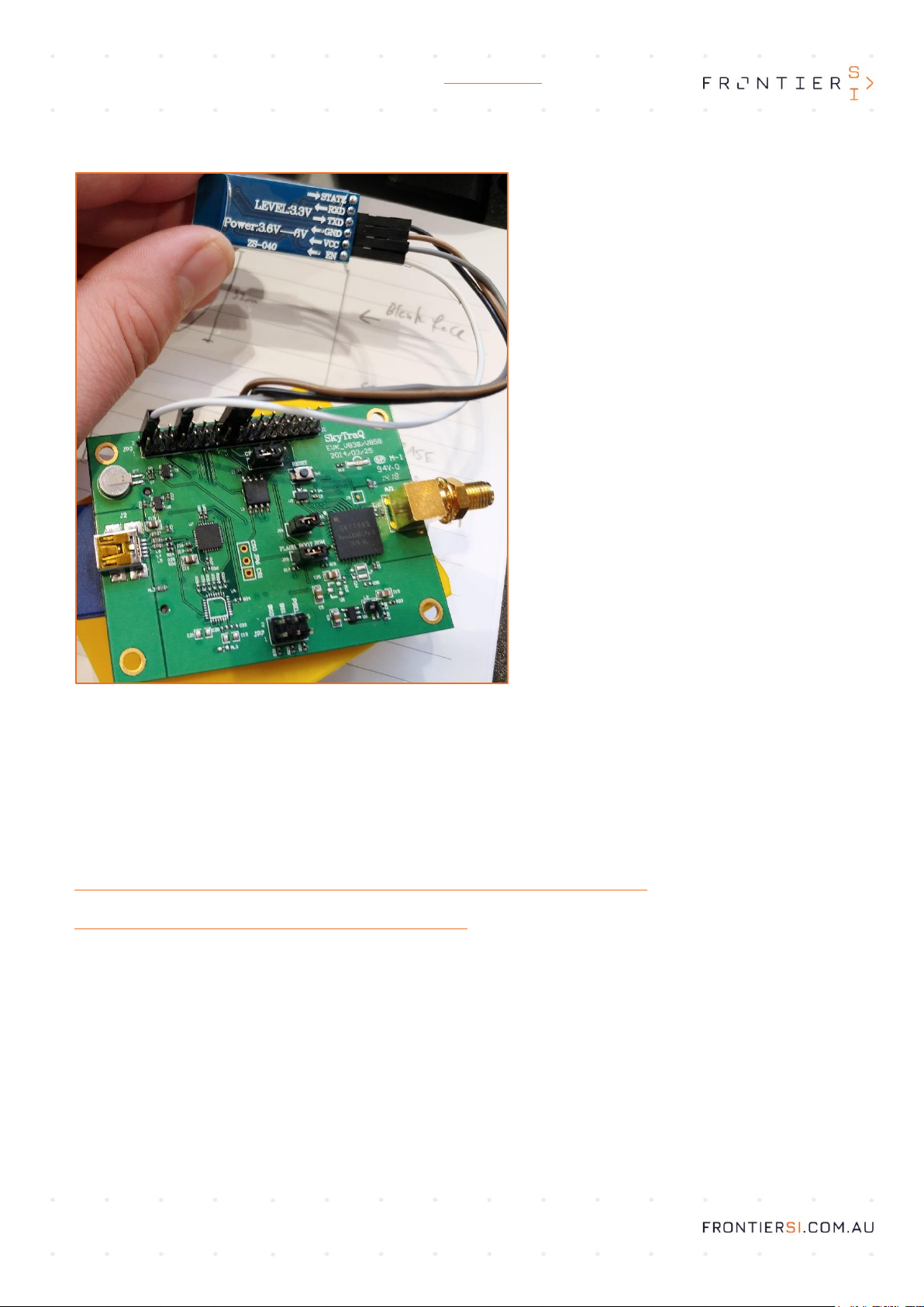
4. Setup and Operation
You should now have a functioning SkyTraq Venus 838 GNSS receiver, which has been configured to use corrections from
the Australia and New Zealand SBAS Test signals, using PRN 122. Once powered on, you can now pair to the HC-06
bluetooth module using a PC or Android phone. If connecting via PC, you will now be able to configure the device and log
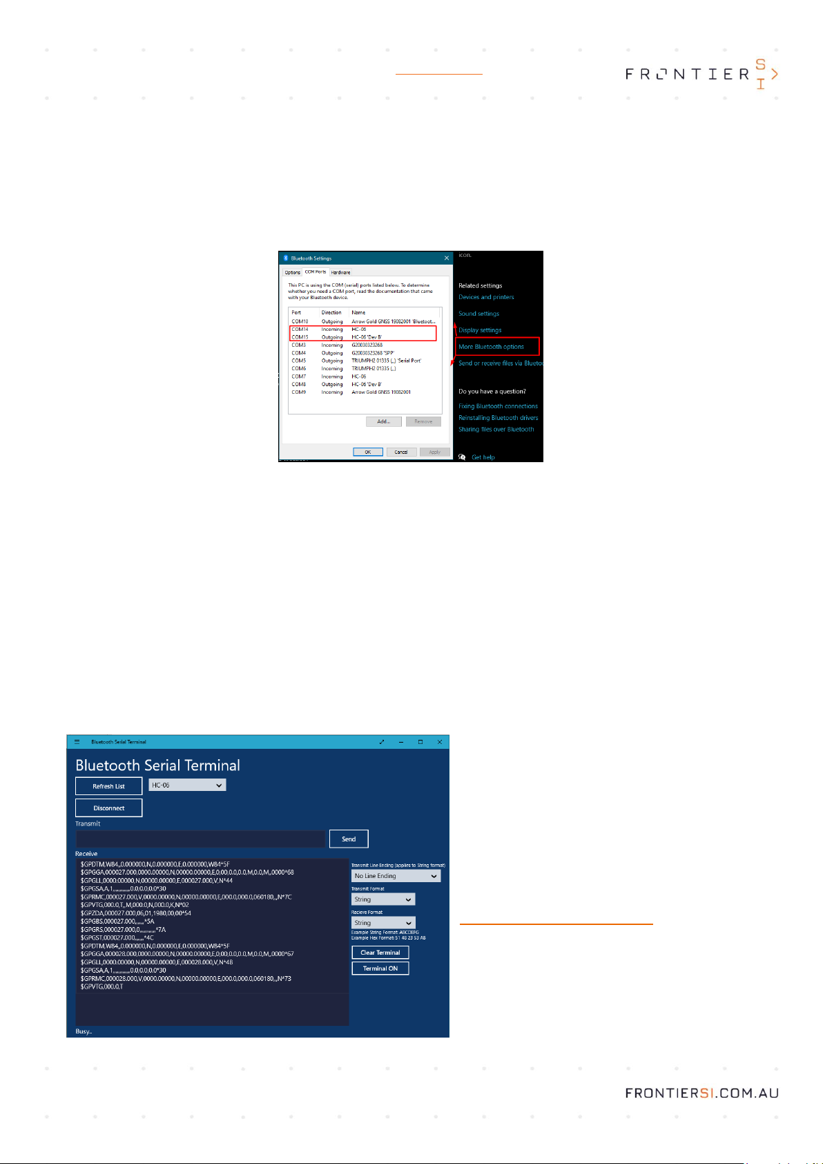
messages via Bluetooth. Once you have paired the HC-06, you can check the Bluetooth COM port using “Bluetooth settings”.
As shown in the image below, you should now see both an incoming and outgoing connection to the device:
You can then use GNSS viewer to connect to the board via this bluetooth COM port. From there you can wirelessly query and
configure the device, monitor location information or log data to a file. This COM port should mirror serial messages from the
SkyTraq to any other software with a real-time receiver input, including GIS software, NMEA logging applications, or Android
Apps. On Android, many apps have in-built support for bluetooth GNSS receivers, however some may require the use of a
“Mock Location” sourced from an app that can take a bluetooth receiver input to function properly.
5. Troubleshooting
The most common issue when constructing this receiver is mis-configured baudrate between the HC-06 and the SkyTraq
board. If they do not match, the communications will not work as expected in either direction. A simple way to test whether
this has been done correctly is to use the “Bluetooth Serial Terminal” windows app, available on the windows app store.
Once you have paired the HC-06, you can select it from the drop-down list, and press “connect”. If you see the NMEA
sentences that you have configured the board to output, then everything is working as expected. If there is no output or the
content is not readable once connected, there may be a baud-rate mismatch, or the HC-06 Rx and Tx may be plugged into
the wrong pin on the SkyTraq. If there are connectivity issues via Bluetooth, try configuring the SkyTraq via USB instead.
For further troubleshooting advice, get in touch with
the positioning team at FrontierSI, and they will do
their best to help.
6. Contact Information
If you would like to discuss the design or assembly
process of this Low-Cost SBAS Receiver based on the
SkyTraq Venus 838FLPx Evaluation kit, please get in
touch with Chris Marshall at FrontierSI.
Chris Marshall
cmarshall@frontiersi.com.au
Licensed under CERN Open Hardware License v. 1.2,
for more information, please read the supporting
documentation included in the package.
Please contact Chris Marshall with information about
manufactured products under this license, and any
modifications made by the Licensee.
Table of contents