Fronus Xtreme Series User manual

Xtreme Inverter
1. Introduction
This inverter is a compact inverter designed to power your home appliances or precious
electronics. Its compact size features easy installation and high movability. Besides, its high
surge capability also can handle motor-type loads such as vacuums, small freezers, or drills.
Compared with traditional inverters in the market, this inverter provides two operation modes:
UPS mode and Inverter mode. At UPS mode, the inverter becomes an UPS which can provide
pure power source to PC-related equipment or sensitive devices. At Inverter mode, the inverter
can provide continuous power to general home appliances.
2. Product Overview
Front View:
Back View & Top View:
Quick Guide
Power Switch
LCD Display
Operation mode selector
AC input
Input breaker
External battery connectors
Charge current selector
Output receptacles

3. Important Safety Warning (SAVE THESE INSTRUCTIONS)
Before using the inverter, please read all instructions and cautionary markings
on the unit, this manual and the batteries.
General Precaution-
Install the UPS in a protected area that is free of excessive dust and has adequate air flow.
Please place the UPS away from other units at least 20 cm to avoid interference. Do NOT
operate the UPS where the temperature and humidity is outside the specific limits. (Please
check the specs for the limitations.)
CAUTION! The unit is designed for indoor use. Do not expose this unit to rain, snow or
liquids of any type.
CAUTION! To reduce risk of injury, only use qualified batteries from qualified distributors or
manufacturers. Any unqualified batteries may cause damage and injury. Do NOT use old or
overdue batteries. Please check the battery type and date code before installation to avoid
damage and injury.
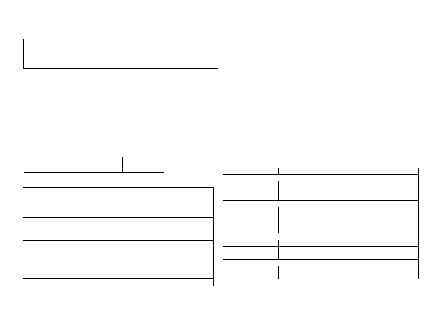
WARNING! It's very important for system safety and efficient operation to use appropriate
external battery cable. To reduce risk of injury, external battery cables should be UL certified
and rated for 105°C or higher. And do not use copper cables less than below cable
recommendation. Below is the external battery cable reference according to system
requirements.
Table 1 Minimum Recommended Battery Cable Size versus Length
Typical Amp.
1 meter (one-way)
Dia-mm
75 A
AWG 6(or 2*AWG10)
4.1151
Table 2 External Battery Cable Size Reference
AWG
(American Wire Gauge
Size)
Dia-mm
(Diameter in millimeters)
Ohms/Kft
(Ohms per 1,000ft or 304.8
meter)
0000(4/0)
11.684
0.049
000(3/0)
10.405
0.0618
00(2/0)
9.2657
0.0779
0(1/0)
8.2513
0.0983
1
7.348
0.1239
2
6.5436
0.1563
3
5.8272
0.197
4
5.1893
0.2485
5
4.6212
0.3133
6
4.1151
0.3962
CAUTION! Do not disassemble the inverter. Contact with the qualified service center when
service or repair is required.
WARNING! Provide ventilation to outdoors from the battery compartment. The battery
enclosure should be designed to prevent accumulation and concentration of hydrogen gas at
the top of the compartment.
CAUTION! Use insulated tools to reduce the chance of short-circuit when installing or working
with the inverter, the batteries, or other equipments attached to this unit.
CAUTION! For battery installation and maintenance, read the battery manufacturer's
installation and maintenance instructions prior to operating.
Personnel Precaution -
CAUTION! Careful to reduce the risk or dropping a metal tool on the batteries. It could spark
or short circuit the batteries and could cause an explosion.
CAUTION! Remove personal metal items such as rings, bracelets, necklaces, and watches
when working with batteries. Batteries can produce a short circuit current high enough to
make metal melt, and could cause severe burns.
CAUTION! Avoid touching eyes while working near batteries.
CAUTION! Have plenty of fresh water and soap nearby in case battery acid contacts skin,
clothing, or eyes.
CAUTION! NEVER smoke or allow a spark or flame in vicinity of a battery.
CAUTION! If a remote or automatic generator start system is used, disable the automatic
starting circuit or disconnect the generator to prevent accident during servicing.
4. Specifications
MODEL
Xtreme 1400
Xtreme 2600
INPUT
Voltage
220/230/240 VAC
Voltage Range
170-280 VAC (Computer mode)
90-280 VAC (Inverter mode)
OUTPUT
Voltage Regulation
(Inv. Mode)
+/-10%
Transfer Time
10 ms typical
Waveform
Simulated Sine Wave
BATTERY & CHARGER
Battery Voltage
12 VDC
24 VDC
Floating Charge Voltage
13.4DC ± 0.25 VDC
26.8 VDC ± 0.5 VDC
Max. Charge Current
10A or 20A
PHYSICAL
Dimension (DxWxH)
293 X 231.5 X 82.5 mm
Net Weight (kgs)
2.35
2.55
Conventions used:
WARNING! Warnings identify conditions or practices that could result in personal injury;
CAUTION! Caution identify conditions or practices that could result in damaged to the
unit or other equipment connected.

5. Installation
NOTE: Before installation, please inspect the unit. Be sure that nothing inside the package is
damaged.
Connect to Utility and Charge
Plug in the AC input cord to the wall outlet. The unit will automatically charge the connected
external battery even though the unit is off.
Connect External Battery
Step 1- Take away the cover of external battery terminal.
Step 2- Following battery polarity guide printed near the battery terminal!
Place the external battery cable ring terminal over the battery terminal.
RED cable to the positive terminal (+);
BLACK cable to the negative terminal (-).
WARNING! Please use the appropriate battery cable. Please refer to Important Safety
Warnings Section for the details.
Step 3- Tight the battery cables with the M5 nuts. Do NOT place anything between the flat
part of battery terminal and the battery cable ring terminal, or overheating may occur.
(See Fig. 1)
Fig.1 Battery cable connects to the inverter
Step 4- Install a DC Breaker in a positive battery line. The rating of the DC Breaker must be
according to the inverter's battery current (75 Amp). Keep the DC breaker off. (see Fig. 2)
Step 5- Connect battery cables to the external batteries.
Note: For the user operation safety, we strongly recommend that you should use tapes to
isolate the battery terminals before you start to operate the unit.
1) Single battery connection(Refer to Fig. 2): When using a single battery, its voltage
must be equal to the Nominal DC Voltage of the unit (see below Table 1).
2) Multiple batteries in series connection(Refer to Fig. 3): All batteries must be
equal in voltage and amp hour capacity. The sum of their voltages must be equal to the
nominal DC Voltage of the unit.
Fig 3
3) Multiple batteries in parallel connection(Refer to Fig. 4): Each battery's voltage
must be equal to the Nominal DC Voltage of the unit.
Fig 4
Step 6- Make sure to connect the polarity of battery side and the unit correctly.
Positive pole (Red) of battery to the positive terminal (+)of the unit.
Negative pole (Black) of battery to the negative terminal (-) of the unit.
Step 7- Put the covers back to the external battery terminals.
Step 8- Take the DC breaker on.
Mounting the Unit
The unit can be mounted to a wall surface. Please follow below steps:
1. Turn off the unit before mounting.
2. Select an appropriate mounting location. Use a horizontal line and the length of the line
must be 222 mm and mark the two ends on the wall. (see chart 1)
3. Drill two marks by screws.
4. Mount the unit by positioning the key-hole slots over the mounting screws.
(see chart 2)
Char 1 Chart 2
Fig. 2
Table 1
Model
Nominal Battery DC Voltage
Xtreme 1400
12 VDC
Xtreme 2600
24 VDC

6. Operation
Power On/Off
Once the inverter has been properly installed, press the power switch to turn on the unit. The
unit will work automatically in line mode or inverter mode according to input utility power's
status. When press the power switch again, the unit will be turned off.
LCD Display & Audible Alarm
Status
LCD Display
Alarm
Line
mode
Unit at power on.
Off
Unit at power off.
Off
Battery
mode
Battery weak
and
will flash every 2
second.
Sounding every 1 sec.
None weak-battery
Off
Fault mode
The mark and
fault code will be
displayed. Short fault: F0
Overload fault: F1
Battery bad: F2
High output voltage: F3
Main Relay Stick:F4
Fan fault: F5
Example:
Continuously sounding for
30 min. and then alarm
off.
The unit is overload.
The mark will
flash every second.
Sounding every 0.5 sec.
Load level indicator: Battery level indicator:
Display
Load Level
Display
Battery Level
75%~100%
battery voltage ≥ 12.5V (25V)
50%~75%
12.5V (25V)> battery voltage ≥
11.5V (23V)
25%~50%
11.5V (23V)> battery voltage ≥
11.0V (22V)
0%~25%
battery voltage < 11.0V (22V)
Operation Mode Selector
a). “UPS”: setting for conventional electrical appliance.
If you select this mode, the unit's input utility range will be 170~280Vac as normal home UPS.
If the utility is higher or lower than this range, the unit will transfer to inverter mode
automatically. And you can connect the computer systems or other precision home
equipment when you select this operation mode.
b). “INV.”: setting for energy saving
If you select this mode, the unit's input utility range will be extended to 90~280Vac. If the
utility is higher or lower than this range, the unit will transfer to inverter mode automatically.
So, you can connect the home equipments, such as light bulb, fluorescent tube, fan, or TV on
this mode.
Caution!! If you select the “INV.” mode and connect the computer to the output of the unit,
the computer may reboot if the input voltage is too low to be accepted.
7. Trouble Shooting
Use the table below to solve minor problems.
Problem
Possible Cause
Solutions
Utility power is
normal but the unit
is in inverter mode.
AC input power cord is not
connected well.
Check AC input power connection.
Input breaker is activated.
Reset the input breaker.
When power fails,
the backup time is
shorten.
The unit is overload.
Remove some non-critical loads.
Battery voltage is too low.
Charge the unit at least 8 hours.
Battery capacity is not full
even after charge the unit for
at least 8 hours.
Check the date code of the battery. If
the batteries are too old, replace the
batteries.
Nothing is display on
the front panel when
the utility power is
normal.
The unit is not turned on.
Press power switch to turn on the
unit.
Battery is not connected well.
Check the external battery cable and
terminal. Make sure all the battery
connections to the unit are all correct.
Battery defect.
Replace the batteries.
Battery voltage is too low.
Charge the unit at least 8 hours.
Inverter fault and
restart circularity.
The unit is overload.
Verify that the load matches the
capability specified in the
specification.
Output short circuit.
Check the load which connect to the
unit, and eliminate short circuit load.
If there is any abnormal situations occur, which doesn't list above, please call the service
people immediately for professional examine.
This manual suits for next models
2
Table of contents
Other Fronus Inverter manuals
Popular Inverter manuals by other brands

LG
LG RESU16H Prime installation manual

Energizer
Energizer eZV3200 user guide

Next Wave CNC
Next Wave CNC SHARK manual

Generac Power Systems
Generac Power Systems PWRcell X7600 Series installation manual

Mitsubishi Electric
Mitsubishi Electric FR-F806-E Hardware instruction manual

Polinovel
Polinovel V+ Series product manual