Frosty Factory 137 User manual

Frosty Factory
of America, Inc.
2301 S. Farmerville St., Ruston, LA 71270
frostyfactory.com
(318) 255-1162 (800) 544-4071 (318) 255-1170 fax
Service Manual
All technical data, pictures and drawings contained in this manual are not binding on the
manufacturer nor can the manufacturer be held liable for any modifications to the
machine in whole or in part. Revised 1/2016
Model 137

2
TABLE OF CONTENTS
1.0 INTRODUCTION
1.1 Use of the Manual
1.2 Preliminary Inspection
1.3 Description
1.4 Dimensions
2.0 SAFETY AND INSTALLATION
2.1 Safety Precautions
2.2 Installation
3.0 OPERATION
3.1 Machine Controls
3.2 The Product You Serve
3.3 Product Consistency
3.4 Start Up
3.5 Freeze Time
4.0 MAINTENANCE
4.1 Cleaning
4.2 Re-Assembly
4.3 Preventative Maintenance
4.4 Extended Storage
4.5 Faceplate/Faucet Assembly
4.6 Float Switch
4.7 Thermostat Assembly
4.8 Using the Cleaning Brushes
4.9 Beater Bar Seal Installation
4.10 Scraper Blade and Spring Seal Installation
4.11 Ceramic Seal Removal and Re-installation
5.0 EQUIPMENT DRAWINGS
5.1 Drive Belt
5.2 Franklin Motor
5.3 Shim Placement
5.4 Rear Cylinder Assembly
6.0 TROUBLESHOOTING
7.0 SPARE PARTS LIST
8.0 WIRE DRAWINGS
9.0 WARRANTY

3
Unpack the unit as soon as possible
upon its arrival. Check the entire
machine and its contents for possible
shipping damage. Note damage on
truck lines and notify your carrier
immediately. All machines are
shipped FOB Ruston, Louisiana, which
means that the machines left our docks
in perfect working order. Frosty
Factory of America is not responsible
for damaged merchandise once the
equipment leaves our dock. Inventory
the accessories to be sure they include
the items you specified on your order.
Normally the accessories include:
SECTION 1
INTRODUCTION
1.1 USE OF THIS MANUAL
Your service manual has been prepared as a guide to help you get the most from your
Frozen Drink Machine. It contains information about the installation and operation of
your machine. The manual also contains instructions for service and care. The manual
should be read carefully by the operator of the Frozen Drink Machine to become familiar
with the machine and the correct operating procedures described within. The following
notations are used throughout the manual to bring important facts to your attention:
“Warning” - This notation is used whenever the personal safety of the operator(s) might
be jeopardized, if procedures are not followed correctly.
“Caution” - This notation is used whenever the machine or related equipment may
receive or cause damage if not observed.
“Note” - This notation is used to bring important information to your attention that
will enhance the performance of your machine.
1.2 PRELIMINARY INSPECTION
WARNING
DO NOT INSERT ANY OBJECTS
INTO CYLINDER OR HOPPER WHILE
MACHINE IS RUNNING!
CAUTION
RISK OF ELECTRICAL SHOCK.
DISCONNECT POWER
BEFORE SERVICING UNIT.
CAUTION
MOVING PARTS
DO NOT OPERATE UNIT
WITH PANELS REMOVED
Beater Bar, Drip Tray, Faceplate,
Faceplate Knobs, Hopper Cover,
Petro-Gel, Sanitizer, Spare Faucet O-Rings,
Warranty Card, Wire Brushes, Manual.

4
26”(66 cm)
1.3 DESCRIPTION
Stainless
Steel Cabinet
Stainless
Steel
Cylinder
Faceplate
Knobs F0262
Clear Plastic
Faceplate
C6501
Drip Tube
Lighted
Flavor Sign
Control Switches
Top F0416
Bottom F0417
Beater Bar
C6527
Faucet
Assembly
C6513
Fill Indicator
Light F0207
Drip Tray
F0195
Scraper Blade
(not visible)
C6510F
16.5” (42cm)
(72cm)
28.5”
1.4 DIMENSIONS
Legs are 4” high.
Allow 6” behind unit for air circulation,
water hoses or remote connections.
24.5” (61cm)
29¼” (74.3cm)
Drip Tray
Insert
F0196

5
WARNING: Do not
attempt to alter the
electrical plug. Serious
injury or electrocution
may result.
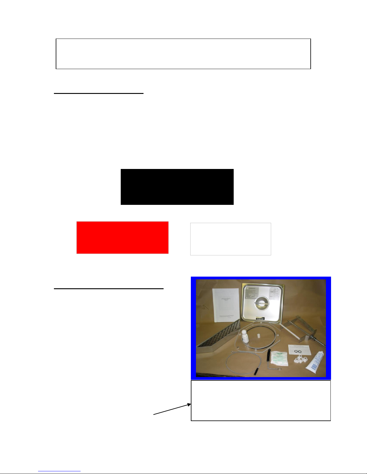
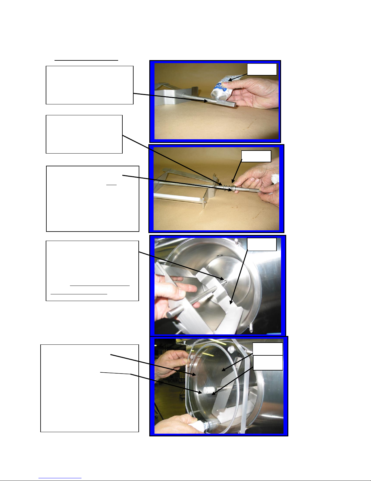
6. Install the drip tray, cover, beater bar and faceplate
assemblies on the Frozen Drink Machine.
SECTION 2
LOCATION & INSTALLATION
2.1 SAFETY PRECAUTIONS
Do not attempt to operate your Frozen Drink Machine until the safety precautions and operating
instructions in this manual are read completely and are thoroughly understood.
Take notice of all warning labels on your Frozen Drink Machine. The labels have been put there
to inform and protect persons operating or servicing your equipment. Care must be taken not to
damage or destroy labels during installation and servicing. The labels have been designed to
withstand routine cleaning and handling. Damaged or missing labels should be promptly
replaced with approved labels from Frosty Factory of America Inc.
2.2 INSTALLATION
Placing your Frozen Drink Machine in a highly visible area will enhance sales. A suitable
station will be able to support 250 pounds and will have a dedicated electrical outlet.
CAUTION: Do not attempt to share the dedicated electrical outlet with any other appliance;
this will cause the circuit breaker to trip.
1. Uncrate your Frozen Drink Machine.
2. The Frozen Drink Machine must be placed on a sturdy platform able to hold the weight of the
machine when full of product. Level the machine by turning the adjustable part of the leg.
The machine must be level front to back as well as left to right.
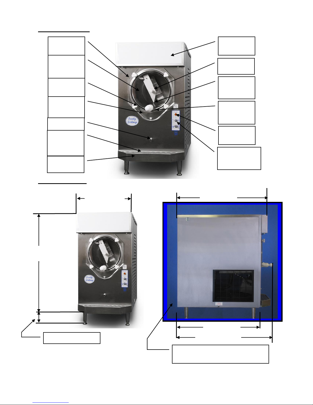
3. Frozen Drink Machines equipped with air cooled condensers must have correct ventilation.
Air intake is at the rear of the Frozen Drink Machine and discharge through the side; both
require 24” clearance and 8” at the back. All Frozen Drink Machines require12” clearance at
the top.
NOTE: Locating the unit in direct sunlight, near cooking facilities or any high
heat area will reduce the performance of your machine.
CAUTION: Extended operations under severe heat condition can damage the cooling
system.
NOTE: Establishments that serve beverages from frozen drink machines are
responsible for providing the necessary facilities for cleaning and
sanitizing their food service equipment.
4. Place the three-position switch in the OFF position (center).
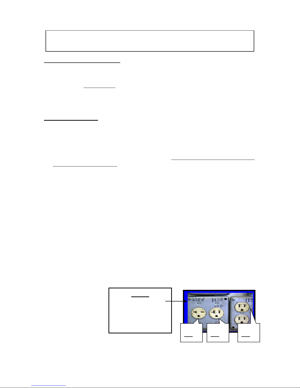
5. Connect the power cord. The Frozen Drink Machine must be connected to a properly
grounded receptacle. The electrical cord furnished as part of the Frozen Drink Machine has
a three or four prong grounding type plug. The use of an extension cord is not
recommended. If one must be used, consult the national and local electrical codes. Do not
use an adapter to get around grounding requirements.
115V
20A
230V
20A
115V
15A
Notice:
Your receptacle should
look like one of these
and match your unit
voltage, amps on the
data plate.

6
SECTION 3
OPERATION
3.1 MACHINE CONTROLS
Two selector switches located on the front of the machine control operation of the
Frozen Drink Machine. Selection of the right (snowflake) position, with both switches,
will schedule the machine for normal operation. The compressor cycle is protected by a
time delay circuit, which will engage the compressor approximately 2 minutes after
normal operation is initiated. A red fill light located above the switches will illuminate
when the level of mix is low in the hopper. A thermostat knob on the electrical control
box of your machine is set at the factory and should not be changed or adjusted except by
an authorized service repairman.
Refer to the information below for functions available with various combinations of
switch positions.
Normal Operation –Both switches on
snowflake. Machine will freeze mix to
provide frozen beverage as desired.
Cleaning Operation - The drive
motor will run in the faucet position
to allow a stirring action of the rinse
water while cleaning.
Off - The hand symbol is the
recognized international symbol for
“stop”. In this position,
the machine will not run.
Cooling Operation –Top switch on
snowflake, Bottom switch on
thermometer symbol. Machine will
automatically come on whenever
necessary to keep mix cooled to
5ºC/40ºF - used primarily for
overnight storage of mix remaining
in the machine.

7
3.2 THE PRODUCT YOU SERVE
The Frozen Drink Machine will produce a fine grain, semi-frozen slush when the proper
mix is used. When measured with a refractometer, the proper mix will measure 13 to 18
“brix”. Too little sugar in the mix will cause larger ice crystals to form. Too much sugar
will lengthen the freeze time.
CAUTION: Any attempt to freeze water only will cause severe damage to your
machine.
NOTE: Do not add sugar directly into the machine, as some of it will settle and
result in an improper mix.
FRUIT JUICES with at least 32 grams of sugar per 8-oz. serving will freeze well in
the Frozen Drink Machine. They will remain stable during the freezing process while
retaining their natural color and flavor.
NEUTRAL BASES are used to produce a neutral frozen cocktail base. A wide variety
of different drinks can be created from one neutral base by the addition of various flavors.
Most brands of neutral bases specify a mixture of four parts water to one part neutral
base. However, before use in the Frozen Drink Machine, be sure the “brix” level is 13 to
18.
The amount of ALCOHOL in the recipe will affect the freezing process. As a rule of
thumb, for the mix to freeze properly, the recipe should contain no more than 25 percent
alcohol.
Suggestion for optimum production and sales:
1) Use the finest ingredients available.
2) Test the product before serving it.
3) Keep the machine clean - ALWAYS!
3.3 PRODUCT CONSISTENCY
An exclusive torque sensing mechanism
developed by Frosty Factory of America
will produce consistent texture and
thickness of your frozen beverages. The
adjustment screw (accessible through the
left side panel as you face the machine
front) is pre-set at the factory. Various mix
consistencies can be achieved by turning
the screw clockwise (thicker drink) or
counter clockwise (thinner drink). Turn
the screw one full turn then allow enough
time to lapse (about three minutes) for the
compressor to complete a cycle before
sampling. Continue this process until
desired result is obtained.
TCC screw is visible through opening at rear of
cabinet (as shown). Use a straight slot screwdriver
to adjust. Clockwise thickens beverage,
counterclockwise makes beverage thinner.

8
3.4 START U
NOTICE: Before start-up, be sure the machine has been sanitized in accordance with
procedures set forth in the cleaning section of this manual.
Pour the mix into the hopper and allow it to drain into the cylinder.
NOTICE: Always add mix as soon as the orange, level indicator light, above the
switches, comes on to prevent air from entering the cylinder.
CAUTION: Allowing air into the cylinder will cause a rocking motion of the machine.
If the mix is not yet frozen the air can escape by turning the machine off for
20-30 seconds.
WARNING:
3.5 FREEZE TIMES
The freeze time on the Frozen Drink Machine Model 137A is approximately 30
minutes when ideal conditions are met. Such as, starting mix temperature of 40
degrees and room temperature at 80 degrees. The time will increase with warm mix or
if the machine is not properly ventilated or is operated in a hot environment. Recipes
with high alcohol or high sugar content will naturally take a little longer.
Never under any circumstances,
place your finger or any other object
into the hopper or feed hole while the
machine is in operation. Serious
personal injury may occur.
When the cylinder is full and the hopper is filled to one inch from the top, the machine is
ready to run. Turn on by selecting the “right” (snowflake) position of both switches on
the front panel.
Fill the
Hopper
to about
1 inch
from the
top
Do not run the
machine when
the freezing
cylinder is not
completely full!
3.4 START UP

9
SECTION 4
MAINTENANCE
4.1 CLEANING
The following cleaning procedure should be used for initial start-up and on an as
needed basis to comply with the minimum cleaning and sanitizing frequencies
specified by the Federal, state or local regulatory agency having jurisdiction.
(1) Turn the machine to the off, “hand” position then remove hopper cover.
(2) If applicable, drain mix into a sanitized container as per local health code procedures.
NOTE: Do not put hands or foreign matter into mix.
(3) Pour two gallons of cool water (75ºF) into the hopper. Place upper switch in
“faucet” position to let the machine stir for 2 minutes. Turn machine “OFF”, drain
and dispose of the rinse water. Repeat until water is clear.
(4) Remove the knobs from the faceplate by turning in a counter clockwise direction.
Carefully pull the faceplate straight away from the front of the machine. Remove the
beater bar assembly from the cylinder. Then slide the spring seal off the rear of the
beater bar. Unscrew white faucet cap to remove faucet
plunger from faucet body. Remove all o-rings for
cleaning.
NOTE: Do not unscrew faucet body from faceplate to
clean. (Leak free service after disturbing the
Teflon seal cannot be assured).
(5) All parts removed during the above steps plus the
drip tray and insert can now be cleaned in your warm
(100ºF) cleaning solution. Rinse all parts in clean
rinse water and allow to air-dry before re-assembly.
(6) Use cloth and cleaning solution to wipe any residue from
cylinder and hopper.
(7) Re-assemble as shown in section 4.2 (next page).
(8) Mix two gallons of warm water (approximately 100ºF
with two ounces of sanitizing powder to achieve 100 parts/million (PPM) sanitizing
solution.
(9) Pour the sanitizing solution into the hopper.
(10) Place upper switch in “faucet” position. Let solution stir for 5 minutes. Turn
upper switch “OFF” (hand) position. Drain all solution.
Notice: Do not leave the solution in the machine for more than 5 minutes.
(11) Pour product into hopper. Replace hopper cover. Place both switches in right
(snowflake) position when ready to freeze product.

10
4.2 RE-ASSEMBLY
Using Petro-Gel, (F0298)
lightly lubricate the longer
end of the beater shaft.
.
Slide beater seal
(F0355) onto the shaft
with the spring end
toward the beater bar.
The black carbon ring
must be facing the end of
the beater bar so it will be in
direct contact with the white
ceramic seal inside the
cylinder when the beater bar
is re-installed.
Carefully insert the large
beater bar C6527 (with
beater seal) into the hole at
the rear of the cylinder and
rotate until it fully engages
into the drive plate.
F0355
Re-install the large faceplate
on the machine. First place
the faceplate bushing onto the
beater shaft. Then slide face
plate onto the four studs.
Install the faceplate knobs and
tighten evenly until the
faceplate O-ring is snug
against the cylinder.
C6527
C6501
-1
C6520
F0298

11
4.3 PREVENTATIVE MAINTENANCE
It is recommended that a maintenance schedule be followed to keep the machine clean
and operating properly.
WARNING: Never attempt to repair or perform maintenance on machine until the main
electrical power has been disconnected
A. DAILY
The exterior of the machine should be kept clean at all times to preserve the luster and
sanitation of the stainless steel. A mild alkaline cleaner is recommended. Use a soft
cloth or sponge to apply the cleaner.
B. WEEKLY
(1) Check O-rings and rear seal for excessive wear and replace if necessary.
(2) Clean faucet and faucet o-rings. Apply Petro-gel to O-rings and inside of faucet body.
(3) Clean the drip tray and front of the freezer with a mild soap solution.
C. MONTHLY
CAUTION: Air-cooled condensers must have proper air circulation. Failure to clean
the condenser on a regular basis may result in loss of refrigeration
efficiency or serious damage and could void warranty.
(1) Visually inspect the condenser for dirt by shining a light through the coil from the
inside of the condenser.
(2) If the condenser is dirty, place a wet towel over the outside of the condenser.
(3) Using compressed air or a CO2 tank, blow out the dirt from the inside of the
condenser. Most of the dirt will cling to the wet towel.
(4) An alternative method of cleaning the condenser is to use a condenser brush and
vacuum.
4.4 EXTENDED STORAGE
Refer to the following steps for storage of the machine over any long period of shutdown
time:
(1) Turn the three position switch to the OFF (center) position.
(2) Disconnect (unplug) from the electrical supply source.
(3) Clean thoroughly with a warm detergent all parts that come in contact with the mix.
Rinse in clean water and dry all parts. Do not sanitize. Frozen Drink Machine parts
can be left disassembled until ready for use.
NOTE: Do not let the cleaning solution stand in the hopper or in the cylinder
during the shutdown period.

12
4.5 FACEPLATE/FAUCET ASSEMBLY
Face Plate/Faucet Assembly Part No.
A. Face plate assembly with bushing C6501
B. Faucet assembly with nut C6513
C. Faucet body (only) C6513B
D. Plunger assembly C6513P
Plunger assembly C6513P
Knob O-Rings Face Plate
F0264 F0491 C6501
O-Ring
F0374
F.P. Bushing
C6520
Faucet Body Faucet Nut
C6513B F0197
Add Teflon Tape

13
4.5 FACEPLATE / FAUCET ASSEMBLY (continued)
Applying Teflon Tape
to Faucet Body
before installation
Lubricating
O-rings with
Petro-Gel
Installing Plunger Assembly
into Faucet body
Install O-rings
onto plunger
Installing large Faceplate
onto front of Machine.
Align Faucet Assembly opening to
bottom of faceplate then tighten nut
C6513
F 0491
F0298
C6513P
C6501

14
4.6 FLOAT SWITCH ASSEMBLY
1. The float switch assembly consists of: Post switch, Float , Float clip, O-Ring
and Nut.
2. There are two dots or a raised ring, on one end of the float. When assembled the
two dots or raised ring must be on the top end of the float.
3. Place O Ring so that it will be inside the hopper (sink bottom) when finished.
Clip
Post Switch
Float Switch Assembly Raised ring
F0811
Float
Bottom of hopper Hex shape for back-up wrench
O-Ring
Nut
Two wires from float switch to control circuit.
Top View of Float Switch
Two dots or raised ring (Up)
Float Clip
Post
4.7 THERMOSTAT SYSTEM-STAND-BY
L1 To upper Switch
2 pos. switch T-Stat
F0401
The two dots or raised
ring, must face upward or
the float switch will
operate backwards.
Thermostat only works
when the switches are in
the “Stand-by” position.

15
4.8 USING THE CLEANING BRUSHES
Drip Chamber
Ceramic Seal
F0665
Q Tip
Cylinder
Drip Tube
Drip Tube Brush
F0327 Drain Spacer Block
C2308
Clean ceramic ring with
warm, wet rag. Remove
any dried product from
center of ceramic ring.
Clean with
warm wet rag
Push brush all the way in
until it can be seen in the
middle of the ceramic ring
Insert long brush
into drip tube
F0327
F0665

16
4.9 BEATER BAR SEAL INSTALLATION
1. Using Petro-Gel (or other sanitary food grade lubricant), lightly lubricate the longer
end of the beater shaft. Slide beater seal onto the shaft with the spring end toward
the beater bar. (Refer to diagram in this section of your manual or on top of the
hopper cover for correct installation of spring seal).
2. The black carbon ring must be facing the end of the beater bar so it will be in direct
contact with the white ceramic seal inside the cylinder when the beater bar is re-
installed. This is a dry seal and must be kept free of lubricants. Lube the beater
bar shaft ONLY!
3. The beater seal may become damaged if the beater shaft is not lubricated before
installation of the beater seal.
Rear wall of cylinder
Ceramic seal inside cylinder
(must be grease free)
Carbon seal face
(Must be grease free)
Rubber seal
Spring
Spring cup
Apply light film of grease
before assembly
Beater bar shaft
Beater seal assembled
and installed
Beater bar assembly
C6527
Damaged seal.
Do not re-use!
Seal with
normal wear.
Properly installed
seal assembly
F0355

17
4.10 SCRAPER BLADE AND SPRING SEAL INSTALLATION
.
Step 1: Attach scraper
blade spring F6512 as
shown.
Step 2: Insert rod
end into beater bar
frame.
Step 4: Apply a small
dab of Petro-Gel F0298
Step 3: Tap scraper
blade rod until it is
centered.
Step 5: Install spring
seal F0355
Step 6: Squeeze and
release spring. Be
sure the spring
returns to normal
before installing into
machine.
Step 7: Install large
beater bar assembly
C6527 into
cylinder.
Step 8: Install large
faceplate C6501
onto machine

18
To remove old seal;
1. Press the “Push button” on the puller tool to
release the ball bearings.
2. Insert “T” handle through ceramic seal at rear of
cylinder.
3. Release “Push button”.
4. Quickly pull “T” handle straight out and the
ceramic seal will remain on the “T: handle as
shown below.
4.11 CERAMIC SEAL REMOVAL AND RE-INSTALLATION
To install new seal;
1. Apply silicone sealant around rear, grooved surface, of
ceramic seal (Put lubricant on the smooth side of the seal
to prevent the silicone from sticking)
2. Press seal into hole at rear of cylinder. Silicone coated
surface goes in first.
3. Gently tap ceramic ring with wood or plastic rod
(DO NOT USE METAL!) until the seal has completely
bottomed out.
4. The smooth surface of the ceramic seal must be
completely clean in order to provide proper sealing when
the beater bar with spring seal is installed.
5. If possible allow at least four hours drying time for
silicone to cure before filling machine with product
6. Fill machine with product and check for leaks.
7. Machine is ready to run.
Puller Tool F0012
Ceramic ring
Note: Use this procedure only when necessary to replace a damaged ceramic seal
DO NOT
hold button
in while
pulling “T”
handle out.

19
5.1 DRIVE BELT All Frozen Drink Machine Models
Frame
Drive Motor F732
Motor Note: Motor stop bracket not shown.
Mount
screws
Drive pulley F0471
380J6 –Belt F0473
Flywheel F6525
½”
1. To increase belt tension, loosen the 4 motor mount screws and pry the entire
motor assembly up until the belt is snug. Re-tighten the motor mount screws.
2. To test the belt tension, press on the belt at the mid-point (arrow). The belt
should move easily for the first ½ inch. It should be difficult to press the belt
more than ½ inch.
3. To align the drive pulley with the flywheel, loosen the Allen screw on the drive
pulley and nudge the pulley forward or back as necessary.

20
5.2 FRANKLIN DRIVE MOTOR
All Frozen Drink Machine Models
1 2 3 4 5 6 7 8 9 10 11 12
1. U-Nuts (2) 5/16-18
2. Microswitch Friction Plate F tba
3. Microswitch F0346
4. Motor (Only) F732
Motor assembly C732
Includes items: 2,3,4,5,8,12.
5. Motor Stop Bracket F1203
6. Tension Spring Lg F0469
7. Spring Adjustment Bracket F4202A
8. Motor Bearing F0738
9. Lock nuts (2) ¼-20
10. TCC Adjustment Screw ½-20x3”
11. Screw, Mtr mt.5/16”- 18 x 3/4
12. Motor Pulley F0471
Table of contents