FSM Colibri Grande PRO User manual

Colibri Grande PRO
User's manual
09.05.2011

OVERVIEW
- 1 -
FEATURES
These DVR adapt H.264 video encoding for 4 or 8 channel inputs and G.723
audio encoding in order to store and replay.
●User friendly GUI and easy to install
●Various recording modes (Motion, sensor, scheduled recording)
●Mass storage hard disk backup through high-speed USB2.0 and eSATA.
●4/8CH Composite Input through RJ45 or BNC connectors
●Mobile viewer for Smartphone
●Talk function for two way communication
●Triplex (Recording, Playback, Networking)
●Supplying DC12V power for camera
●Spot monitor for Public view support
●Web monitoring, Remote client SW, Remote setup
●Easy to control of the PTZ camera
●USB Mouse operation
●E-mail notification
●Abnormal shutdown detection and system auto recovery
●High quality and high performance

Specifications – GRM Series
Best, High, Normal, Low / Timer, Motion, SensorQuality / Event type
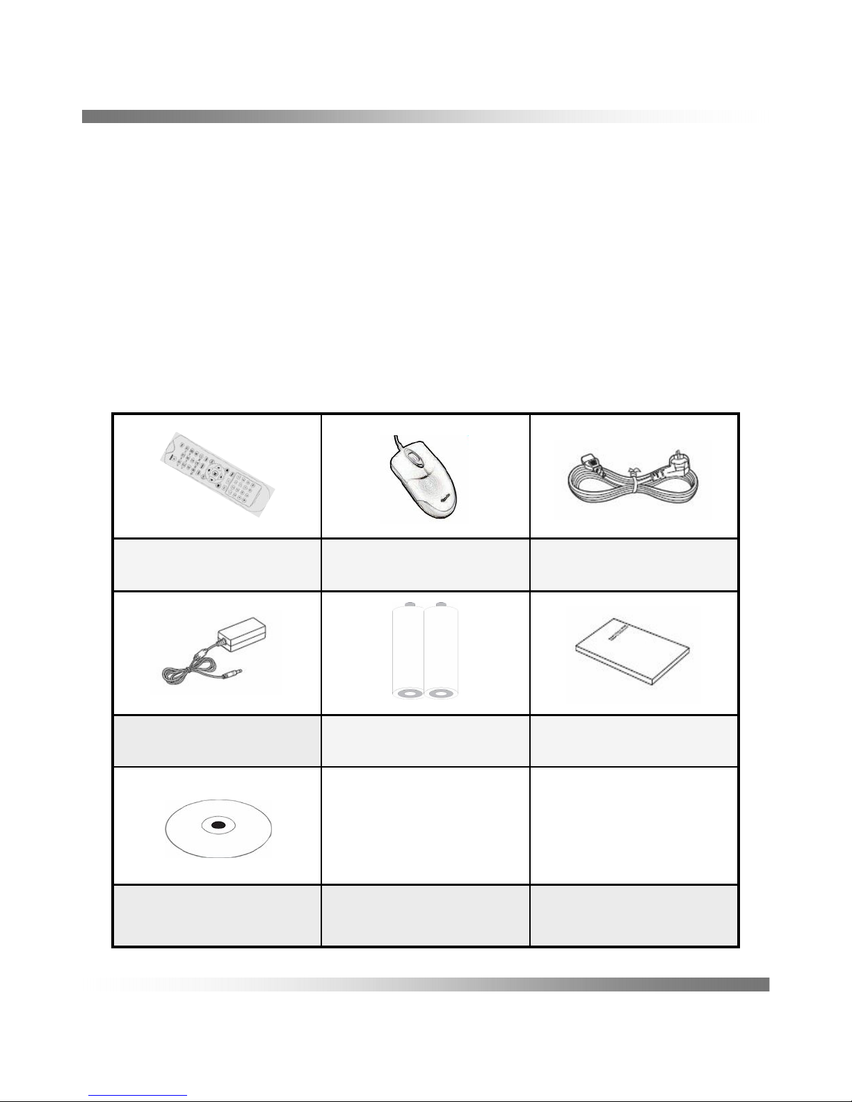
Remote Controller / USB Mouse / NetworkControl Device
4 Input, 1 Output (Relay)8 Input, 2 Output (Relay)Input / OutputAlarm
DC 12V / 6A (72W)
0 ℃~ 45 ℃/ -15 ℃~ 55 ℃Operating / StorageTemperature
DC 12V / 8.33A (100W)Power
Pre/Post Event Recording, Summer time, Time SynchronizationOther Function
WEB monitoring, Remote client SW, Remote setupBrowser
Network
Timer, Motion, SensorSearch
380 X 348 X 60 (Excluded Stand)Dimension [mm] (WxHxD)
CIF (352X240 / 352X288)
120fps / 100fps
CIF (352X240 / 352X288)
240fps / 200fps
HALF D1 (704X240 / 704X288)
120fps / 100fps
HALF D1 (704X240 / 704X288)
240fps / 200fps
D1 (704X480 / 704X576)
120fps / 100fps
D1 (704X480 / 704X576)
120fps / 100fps
17” / SXGA17” / SXGA, 22” / WSXGA+Inch / ResolutionLCD
IN: 4CH / OUT: - / Built-inIN: 8CH / OUT: - / Built-inIn / Out / Speaker
7.0㎏(15.4 lbs) / 9.3㎏(20.5 lbs)7.2㎏(15.9lbs) / 9.5㎏(20.9lbs)Weight (Approx.) Net / Gross
TCP/IP, DHCP, DDNS / Two-way network audioProtocol / Function
RJ45, EthernetPhysical / Mac Layer
eSATA, USB interfaced storage, Network / Watermarking, AVI FormatDevice / FormatBackup
RS-485Signal typePTZ
Recording, Relay out, E-mail notification, Log file, Remote, Buzzer output, Pop Up Action
Sensor In, Motion detection, Video Loss, HDD EventSource
Event
44X30 Grid / 5 StepsResolution / SensitivityMotion detect
Write once / OverwritingMode
HDD(S-ATA) / No limitedType / Capacity
Storage
Abnormal Off detection, Auto recovery, Event log file, USB or Network F/W UpdateSystem Functions
NTSC: 30fps / 15fps / 10fps / 7fps / 5fps / 3fps / 2fps / 1fps
PAL: 25fps / 13fps / 8fps / 6fps / 4fps / 3fps / 2fps / 1fps
Frame Rate
Recording Resolution
H.264Video CODEC
NTSC / PAL Auto detection (Signal check)Format
Video Record
1,4,Sequence/ Graphic User Interface1,4,6,8,9,Sequence/ Graphic User InterfaceDivision / InterfaceScreen
Selectable Output: 4CH(RJ45)Selectable Output: 8CH(RJ45)Talk Output
Audio (Option)
1 CH Composite (BNC)Spot Out
Composite (BNC)Composite (BNC), S-Video (4pin Mini DIN)Monitor out
Video Out
4 X RJ-45, 4 X BNC8 X RJ-45, 8 X BNCNo. of ChannelVideo In
NTSC : 120fps, PAL : 100fpsNTSC : 240fps, PAL : 200fpsLive SpeedMain display
4Channel8ChannelSpecification
- 2 -

Instructions
- 3 -
Thank you for buying GRM DVR series
This is the user manual for GRM DVR series. Before installing or operating this product,
please familiarize yourself with this user manual.
We retain the copyright on this manual. Therefore, with the exception of copying for
general use within the copyright law, copying and reprinting the user manual, either
partially or in its entirety, or translating it into another language without our prior written
approval.
Product warranty and limits of responsibility
Product warranty does not cover cases of accidents, negligence, alteration, misuses or
abuse. In addition, no warranty is offered for any attachments or parts not supplied by
the manufacturer.
We are not liable for any or all losses to the product incurred by your use of non-
standard product or violation of instructions mentioned in this manual.
The following cases are not covered by the warranty and payment is required for
repairs.
●Malfunction due to negligence in handling by the user
●Deliberate disassembly and replacement by the user
●Connection of an improper power supply
●Malfunction caused by natural disasters (fire, flood, etc.)
Warranty only refers to the warranty covering products that have been paid for.
After expiration of the warranty period, examination and repair will be provided for a
fee. Even during the warranty period, repair and examination of items outside the
preceding warranty scope will require a payment.
Before Start
This user manual provides Information for using DVR such as brief introduction part
names, functions, connection to other equipment, menu setup, and the like. You
have to keep in mind the following notices:
If you want to open the case of your system for checking problems,
please consult the expert from the shop where you bought the product.
Before operating the DVR

Safety Precautions - Warnings
The symbol is intended alert to know in order to prevent
serious injury or death and Warnings are described below.
※Before the installation
• Various experience and technical is needed for installation of this product.
All installation operations should be performed by the agency you purchased
this product from.
• Before connecting the AC power cord to the DC adaptor outlet, make sure the
voltage designation of the DC adaptor corresponds to the local electrical supply.
• Do not touch the power cord with wet hands and avoid install under humid
conditions or space
• Use only a properly grounded plug and receptacle.
An improper ground may cause electric shock or equipment damage.
• Make sure the POWER is OFF before installation
• Do not overload multiple wall outlets, extension cords or adaptors beyond their
capacity since this can result in fire or electric shock.
• Do not touch the power plug with wet hand and conductor materials etc.
Doing so can cause electrical shock and fire
• Never insert anything metallic or your hand into the open parts of this apparatus
Doing so many create a danger of electric shock.
• Make sure to plug the power cord in until it is firmly inserted. When pulling the
power cord, do not excessive force. Do not touch the power cord with wet hands.
- 4 -
Before operating the DVR

Safety Precautions - Cautions
The symbol is intended alert to know in order to prevent
minor injury or product damages and cautions are
described below.
※During installation
• Keep the required distances between the product and other objects (e.g. walls)
to ensure proper ventilation. Failing to do so may result in fire or a problem with
the product due to an increase in the internal temperature of the product.
• Do not install or place the product in an unstable location such as a shaky
self a slanted floor or a location exposed to vibration.
• Do not place this apparatus near or over a radiator or heat resistor or where it is
exposed to direct sunlight.
※During use
• Do not move the product while it is operating.
• Do not connect the jacks or cables while your product is turned on.
• Do not allow children to hang onto the product.
• If this apparatus does not operate normally - in particular, if there are any
unusual sounds or smells coming from it - unplug it immediately and contact
an authorized dealer or service center.
• When you install two batteries of remote controller make sure to match the
polarity of the batteries.
• Product design and specifications may be changed without notice in order to
enhance product performance.
• The slots and openings in the cabinet are provided for necessary ventilation to
ensure reliable operation of this apparatus and to protect it from overheating,
these slots and openings must never be blocked or covered.
• This apparatus use batteries require you to dispose of batteries properly for
disposal or recycling information. Use the same type battery.
- 5 -
Before operating the DVR

- 6 -
FCC Compliance Statement
Caution : Any changes or modifications in construction of this device which
are net expressly approved by the party responsible for compliance could
void the user’s authority to operate the equipment.
This device complies with part 15 of the FCC Rules. Operation is subject to the following two
conditions: (1) This device may not cause harmful interference, and (2) This device must accept any
interference received, including interference that may cause undesired operation.
Note : This equipment has been tested and found to comply with the limits for a Class A digital
device, pursuant to part 15 of the FCC Rules. These limits are designed to provide reasonable
protection against harmful interference when the equipment is operated in a commercial environment.
This equipment generates, uses, and can radiate radio frequency energy and, if not installed and
used in accordance with the instruction manual, may cause harmful interference to radio
communications. Operation of this equipment in a residential area is likely to cause harmful
interference in which case the user will be required to correct the interference at his own expense.
Before operating the DVR

INDEX
- 7 -
OVERVIEW
Before Operating the DVR
INDEX
Package Contents
Optional accessories
Remote Controller
Product exterior
Connecting to other devices
RJ-45 Port Layout
Installation the HDD
Getting Started
Live Mode
Setting the Menu
MAIN MENU
SYSTEM
1 FEATURES
2 Specifications
3 Instructions
4 Safety Precautions - Warnings
5 Safety Precautions - Cautions
6 FCC Compliance Statement
7
9 Package Contents
10 Optional Cable Adapter
11 Parts name and Functions
12 8 Channel - Front, Back and Bottom
13 4 Channel - Front, Back, and Bottom
14 Exterior Names and Functions
15 Connecting to the 8 channel
16 Connecting to the 4 channel
17 Connecting to the RS-485, Sensor
18 Cam Input Pin Assignment
19
20 Starting the System
Power off the System
Screen ON/OFF
21 Started Login
22 Icons on the Live Screen
23 Main Menu Icons
24 Menu Explanation
25 Setting the System Name
26 Password

INDEX
- 8 -
SYSTEM
RECORD
CAMERA
REPLAY
EVENT LOG
DISPLAY
SOUND
BACKUP
NETWORK
HDD
PTZ CONTROL
HELP
REMOTE CONTROL
27 Setting System ID
27 System configuration
28 Time / Date Change
29 Firmware Update
29 Hardware / IP / MAC Address etc
30 Setting the Record
31 Setting the event
32 Motion Detection
34 Recording Schedule
36 Camera Setting
37 PTZ Camera Setting
38 Search
39 Event Search
39 Replay
40 Event Log
41 Display
42 Sound
43 Backup
44 Network Configuration
45 DDNS
46 E-Mail notification
47 Setting HDD
48 Controlling a PTZ device
49 HELP
50 Installing the SMART VIEWER
51 DVR LIST SETUP
57 What is Web Viewer
58 Connecting the Smartphone

Please unwrap the product, and place the product on a flat place or in the
place to be installed.
Please check the following contents are included in addition to the main unit.
Package Contents
- 9 -
Users ManualBattery AAA x 2DC Power Adapter
Remote Client CD
Power CordMouse (USB)Remote Controller

Optional Accessories
- 10 -
Optional Cable Adapter
GC-N50
GC-N40
GC-C40
GC-C30
GC-C20
GC-C10
RJ45(M) to
BNC(F) / RCA(F) / PWR(F)
RJ45(F) to
BNC(M) /RCA(M) /PWR(M)
RJ45(F) to
BNC(M) /RCA(M) /RS485
RJ45(M) to
BNC(F) / PWR(F)
RJ45(M) to
BNC(F) / RCA(F)
RJ45(M) to
BNC(F)

Parts name and Functions
1. POWER : System power On/Off.
2. REC : Start or Stop emergency recording.
3. Split Screen
4. OSD : On or Off OSD of screen
5. SEARCH : Display search menu.
6. MENU : Display main menu.
7. ESC : Cancel Setting or Moving Menu.
8. ENTER : Select to menu.
9. Direction : Moving cursor up/down,
left/right
10. Pause : Used to pause
11. Backward : Backward play
12. Forward : Forward play
13. PAN/TIL T: Sets PTZ Mode ON/OFF.
14. ZOOM/FOCUS : Set zoom and focus of
PTZ camera.
15. PRESET : Displays the Preset Setup
16. Numbers : Used as the numeric input
keys, or displays a single channel
Change ID of Remote control
Select ID numbers and pressing over 3seconds.
The system ID of DVR and ID of the Remote controller should be same to control.
1 2
3
4
5
6
7 8
910
11 12
13 15
14
16
Remote Controller
- 11 -

Product exterior
- 12 -
8 Channel – Front, Back and Bottom
Bottom
1652 34
RECORD ALARM
Front
5
1 2 34
5
6
4
CVBS
OUT
SPOT
OUT
1 2
34
56
78
CAM
D+
D- RS-485
1
2
3
4
GND
6
7
8
9
GND
NO
C1
NC
NO
C2
NC
SENSOR
RELAY
OUT
3
12
Back

- 13 -
Product exterior
4 Channel – Front, Back and Bottom
RECORD ALARM
Front
5
1 2 34
Back
5
6
4
CVBS
OUT
SPOT
OUT
1 2
34
CAM
D+
D- RS-485
1
2
3
4
GND
NO
C1
NC
SENSOR
RELAY
OUT
3
12
Bottom
152 34

Exterior Names and Functions
- 14 -
USB port (for data backup and FW update)
USB5
Name
4
3
2
1
NO
Alarm
Power
Red : Power off
Orange: Screen off
Green : Operation
Lighting occurred event.
Lighting during recording
Record
Receive remote control operationReceiver
F
R
O
N
T
Function
POS
6
5
Alarm Output port
Relay out
Composite Video Signal Input Port
(BNC type connector)
Video in
3
Out port composite. (BNC)CVBS out
1
B
A
C
K4
2
Used for RS-485 communication (D+, D-)
RS-485
Out port Live image. (BNC)Spot out
Alarm Input port
Sensor In
Output Port Separated Video signalS-Video
6
DC12V Power inputPower input
5
Connection terminal for external eSATA HDD or
HDD for backup
eSATA4
Used to Network with other devicesEthernet2
Input Video Signal (RJ45 Type)CAM In
1
B
O
T
T
O
M
USB USB port (for mouse)
3

- 15 -
Connecting to other devices
Connecting to the Bottom for 8 channel
eSATA
USB
Devices
RJ-45
Camera In X 8 PC
NETWORK
Monitor Power Adaptor
DC 12V
Connecting to the Back
CVBS / Spot out
Composite
Alarm Sensor #1-8
CVBS
OUT
SPOT
OUT
1 2
34
56
78
CAM
D+
D- RS-485
1
2
3
4
GND
6
7
8
9
GND
NO
C1
NC
NO
C2
NC
SENSOR
RELAY
OUT
BNC
Camera Input X 8

- 16 -
Connecting to other devices
Connecting to the Back
CVBS / Spot out
Composite
BNC
Camera Input X 4
Alarm Sensor #1-4
CVBS
OUT
SPOT
OUT
1 2
34
CAM
D+
D- RS-485
1
2
3
4
GND
NO
C1
NC
SENSOR
RELAY
OUT
eSATA
USB
Devices
RJ-45
Camera In X 4 PC
NETWORK
Power Adaptor
DC 12V
Connecting to the Bottom for 4 channel

Connecting with the other devices
- 17 -
Connecting the 4Channel Sensor in / Relay out / RS-485
4G
321
SENSOR IN (ALARM IN)
NCC1NO
ALARM OUT :
0.5A 125VDC / 1.0A 24VDC
D+
D- RS-485
1
2
3
4
GND
NO
C1
NC
SENSOR IN
RELAY OUT
R+
R-
T+
T-
D+
D-
RS-485
Connecting the 8Channel Sensor in / Relay out / RS-485
NO NCC2NCC1NO
ALARM OUT : 0.5A 125VDC / 1.0A 24VDC
4 G9876G321
SENSOR IN (ALARM IN)
D+
D- RS-485
1
2
3
4
GND
6
7
8
9
GND
NO
C1
NC
NO
C2
NC
SENSOR IN
RELAY OUT
R+
R-
T+
T-
D+
D-
RS-485

RJ-45 Port Layout
- 18 -
Cam Input Pin Assignment
※Camera Power limit
The power limit is 300mA per camera from the DVR.
If you want to use over 300mA of camera, you must use
separate power sources.
⑧⑦⑥⑤④③②① ⑧⑦⑥⑤④③②①
TALK
VIDEO IN
GND
GND
AUDIO IN
DC 12V
D-
D+
GND
⑤
AUDIO INPUT
④
DC 12V OUTPUT (under 300㎃)
③
RS-485 D-
②
RS-485 D+
①
⑧
⑦
⑥
NAME
TALK OUTPUT
VIDEO INPUT
GND
FUNCTION
CAM IN
(DVR side)
PLUG
(CAM side)

Installation the HDD
- 19 -
Managing the HDD
The HDD is very sensitive device, please ensure that the HDD free from shock.
We are not liable for any damage to the HDD incurred by the user’s carelessness
and miss use.
The HDD may be damaged if the DVR is moved or impacted during the HDD operation.
Please backup data as often as possible to minimize the risk of data loss from a
damaged HDD.
The HDD also may be damaged if the DVR is stopped by a power off during the HDD
Operation.
Installation the HDD
There are many factor that cause an electric shock and a fault inside the DVR.
You can contact the retailer to get information including the compatibility list before
installation the HDD.
You must check the brand and Model name that is in the compatibility list before
Installation.
Please check the number of screws and connection wire after Installation the HDD.
If there are wrong connection or feeling the wire, it causes a fault of the DVR .
This manual suits for next models
1
Table of contents