FSR MAS-7000 Installation guide

MAS-7000
MAS-7000A
AV SWITCHER SCALERS
INSTALLATION AND OPERATING GUIDE
43950 LIT1337D10
BASED ON FIRMWARE REV 370
Video Products Group

2
MAS-7000
COMPLIANCE AND SAFETY
PROPRIETARY INFORMATION
All information in this manual is proprietary to and the property of FSR Inc. This publication is protected by the
Federal Copyright Law, with all rights reserved. No part of this document may be reproduced, transcribed, or
transmitted, in any form or by any means, without prior explicit written permission from FSR Inc.
OPERATOR’S SAFETY SUMMARY
The general safety information in this summary is for operating personnel.
Read Instructions. Read and understand all safety and operating instructions before using this equipment. Keep
the instructions handy.
Removal of the top cover may expose dangerous voltages. To avoid personal injury, disconnect all power sourc-
es before removing the top cover. Do not operate the unit with the cover removed.
Power Source:
This product is intended to operate from the power source detailed in the specification section of this manual.
Do not use any other power source or exceed voltage limits.
Grounding the Product:
This product is grounded through the grounding conductor of the power cord. To avoid electrical shock, plug the
power cord into a properly wired receptacle before connecting to the product input or output terminals.
Use the Proper Power Cord Use only the power cord and connector specified for your product. Use only a power
cord that is in good condition. Refer cord and connector changes to qualified service personnel.

3MAS-7000
TABLE OF CONTENTS
COMPLIANCE AND SAFETY............................................................................................................................2
PROPRIETARY INFORMATION................................................................................................................................................2
OPERATOR’S SAFETY SUMMARY..........................................................................................................................................2
INTRODUCTION..................................................................................................................................................5
INSTALLATION ..................................................................................................................................................6
TYPICALAPPLICATION ...................................................................................................................................6
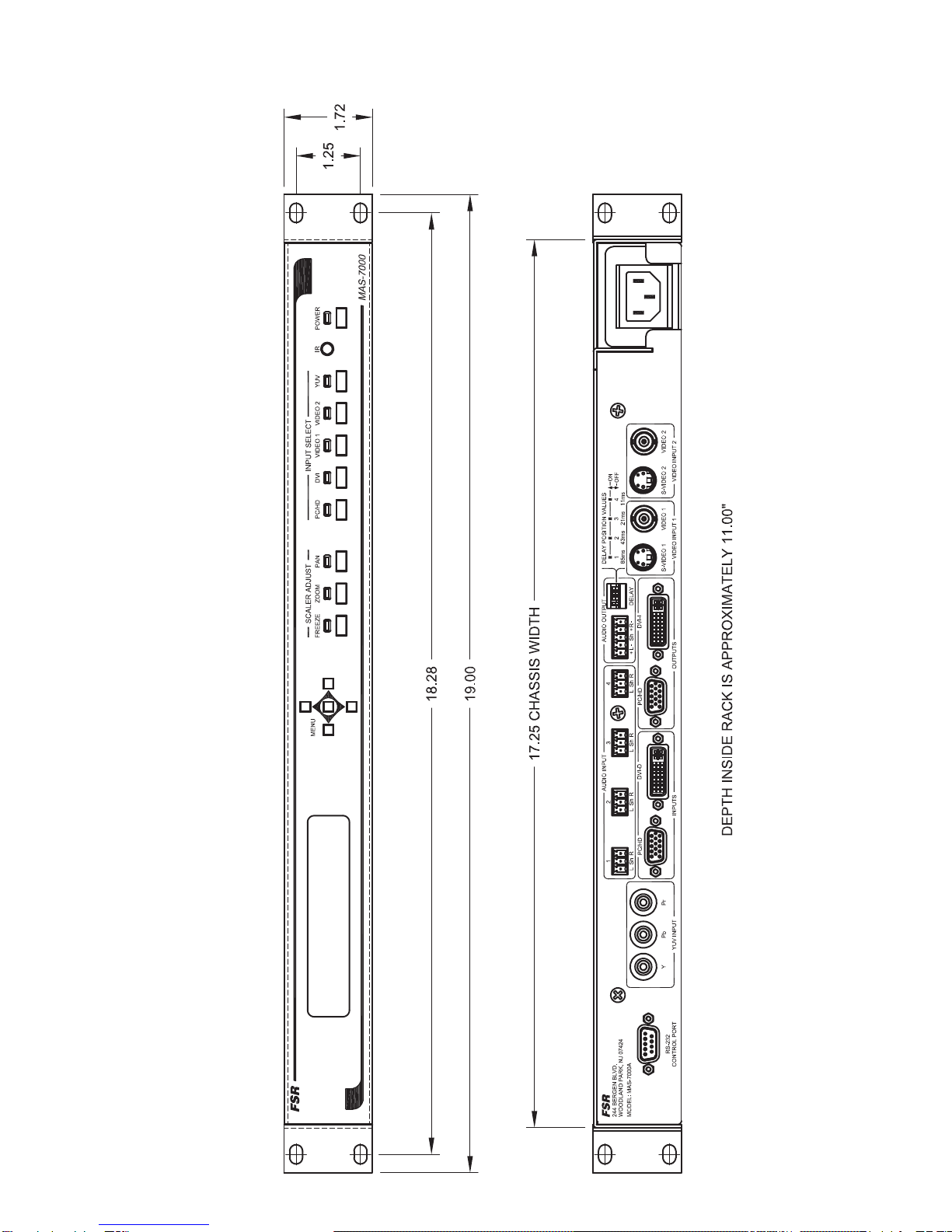
MECHANICAL DIMENSIONS...........................................................................................................................7
FRONTAND REAR PANEL OPERATION.......................................................................................................8
FRONT PANEL CONTROL BUTTONS......................................................................................................................................8
SPECIAL BUTTON COMBINATIONS AND THEIR FUNCTIONS .........................................................................................9
REAR PANEL CONTROLS .........................................................................................................................................................9
ACCESSING AND USING THE ON SCREEN MENUS................................................................................10
MENU NAVIGATION BUTTONS.............................................................................................................................................10
MAS-7000 MENU TREE ...........................................................................................................................................................11
THE ROOT MENU STRUCTURE ............................................................................................................................................12
ADJUST PRESET.......................................................................................................................................................................12
OUTPUT ADJUST GROUP .......................................................................................................................................................12
SCALER ADJUST GROUP........................................................................................................................................................14
INPUT ADJUST GROUP ...........................................................................................................................................................18
RGB / YUV INPUT SUB MENU ITEMS ..................................................................................................................................18
DVI-D SUB MENU ITEMS .......................................................................................................................................................24
CV & YC INPUT SUB MENU ITEMS......................................................................................................................................26
ADJUST RESOLUTIONS GROUP............................................................................................................................................28
SYSTEM SETTINGS GROUP...................................................................................................................................................31
IR REMOTE CONTROL COMMANDS..........................................................................................................34
PINOUTS AND CABLING.................................................................................................................................35
HD15 CONNECTOR..................................................................................................................................................................35
4 PIN MINI-DIN S-VIDEO CONNECTOR (YC) INPUT.........................................................................................................35
DVI-I CONNECTOR PINOUT ..................................................................................................................................................36
AUDIO WIRING ........................................................................................................................................................................37
DB9 CONNECTOR ....................................................................................................................................................................38

4
MAS-7000
MAS-7000 RS232 CONTROL SPECIFICATION............................................................................................39
COMMUNICATION PROTOCOL BASICS..............................................................................................................................39
PACKET FORMAT.....................................................................................................................................................................40
FRONT PANEL BUTTON EXAMPLES ..................................................................................................................................42
FUNCTION LIST........................................................................................................................................................................45
MAS-7000 SPECIFICATIONS...........................................................................................................................49
WARRANTYAND RETURN INFO..................................................................................................................51
WARRANTY POLICY ...............................................................................................................................................................51
SERVICE AND RETURN AUTHORIZATION .........................................................................................................................51
CONTACT INFORMATION ......................................................................................................................................................51

5MAS-7000
INTRODUCTION
The MAS-7000 is a multi-purpose Video Switcher/Scaler is ideal for boardroom and house of worship presentation
systems. The MAS-7000 provides high quality scaling from Standard Definition, High Definition and Computer video
sources to resolutions that match your projector, plasma or HD display.
The MAS-7000A adds a 4x1 stereo audio routing switcher with balanced output and adjustable delay to keep the audio
and video in sync. A rear panel terminal block provides input and output access.
Both models have two Composite Video Inputs (BNC), two S-Video Inputs (4 pin Mini-DIN), one Component Video
Input (3 RCA), one Computer /Component Input (HD-15) and one DVI-D Input on a DVI-I connector. Both NTSC and
PAL are supported.
The units have one Computer/Component output on an HD-15 connector and one DVI-D output on a DVI-I connector
The scaled output is adjustable at any computer resolution up to 2048x2048 as well as all HDTV resolutions up to 1080p.
All settings are stored in non-volatile memory and are retained even when power is switched off. Ten user
defined presets are also available to customize settings for various applications. A front panel LCD makes setup easy.
The MAS-7000 can be controlled in a variety of ways. The front panel along with an LCD display handle all set-up and
switching features. The 7000 can also be remotely controlled from the FSR Room Navigator, an external control system
via the RS-232 serial port or the IR Port.
To make IR control easy and painless, all IR codes are provided in a CCF format and are available on the FSR web site.
These can be used in nearly any universal remote control or from any control system with IR output.
In addition to the standard scaling and switching capabilities, the MAS-7000 has pan, zoom and a host of other features
normally found on much more expensive products. Variable Zoom to 10X enlarges any part of the computer screen to
fill the entire video screen and position controls allow movement to any area desired. Variable Shrink to as little as 10%
allows fitting the image onto most displays. The high sampling rate ensures crisp, clear images, while full bandwidth
chroma sampling ensures faithfully reproduced, high resolution colors. Motion compensation, diagonal interpolation and
a 3:2 Pull-down feature for NTSC significantly improve the image quality. Temporal interpolation greatly improves frame
rate conversion by analyzing and merging successive frames. Pixel Level Motion Adaptive Diagonal Interpolation ensures
high quality de-interlacing of PAL and NTSC signals.
FEATURES:
• Automatic Incoming Resolution Detection
• 2 Outputs: 1 Computer/Component, 1 DVI-I
• Inputs: 2 Composite; 2 S-Video; 1 Component; 1 Computer / Component; 1 DVI-I
• Computer Resolutions to 2048x2048
• HDTV Resolutions to 1080p
• Multiple Worldwide Television Standards
• RS-232 and IR Control
• Image Pan and Zoom
• All Input Types are Scaled
• Image Rotation and Automatic picture sizing
• 4x1 Stereo Audio Switcher with Balanced Output and
adjustable delay (MAS-7000A)

6
MAS-7000
INSTALLATION
The MAS-7000 mounts easily into a standard 19” rack. It should be placed in an area where the user can easily
access the front panel controls. The units are designed to be rack mounted and are supplied with front rack-
mount hardware.
When rack mounting the unit, remember that the maximum ambient operating temperature for the unit is 40
degrees C. Leave at least one inch of space front and rear to make sure that the airflow is not restricted.
When installing equipment into a rack, distribute the units evenly to prevent hazardous conditions that may
be created by uneven weight distribution. Connect the unit only to a properly rated supply circuit. Reliable
grounding (earthing) of rack-mounted equipment should be maintained.
TYPICALAPPLICATION
1234
br
OFF
ON
4
11ms
21ms
3
2
43ms
85ms
DELAY POSITION VALUES
1
MODEL: MAS-7000A
WOODLAND PARK, NJ 07424
244 BERGEN BLVD.
RS-232
CONTROL PORT
VIDEO 2S-VIDEO 2VIDEO 1S-VIDEO 1
VIDEO INPUT 1
PYP
YUV INPUT
34
21
ShLR ShLR ShLR RLSh
AUDIO INPUT
PC/HD
INPUTS
DELAY
+-
RL-
+Sh
AUDIO OUTPUT
VIDEO INPUT 2
PC/HD
OUTPUTS
DVI-D DVI-I
FSR
CONTROL
SYSTEM LAPTOP
PROGRESSIVE
SCAN DVD
STEREO SOUND
SYSTEM
VIDEO
CAMERA
PC
HD
DISPLAY
PROJECTOR
DVD
DVD
VCR

7MAS-7000
MECHANICAL DIMENSIONS
(MAS-7000A MODEL SHOWN)

8
MAS-7000
FRONTAND REAR PANEL OPERATION
FRONT PANEL CONTROL BUTTONS
POWER ON OFF
Pressing the power button will power up the MAS-7000. The unit will run a brief diagnostic sequence
and be operational in a few seconds. Pressing and holding the power button for two seconds and
releasing will power down the unit.
INPUT SELECT
Press and release any of the five input select buttons to select and display the desired video source. An
audio switch will follow if there is an audio input associated with the new video input selected. (MAS-
7000A only). See “Audio Input Number” setting under Input Setup for details on audio input setup
selection and muting.
TRANSITION CONTROL BUTTONS:
FREEZE
Press and release to freeze the current display. This does not affect the background image. A second
press will unfreeze the display. This setting is also available through the on screen menu.
ZOOM
Press and release to enable ZOOM. The LCD display will show the zoom menu and allow adjustments
PAN
Press and release to enable PAN. The LCD display will show the pan menu and allow adjustments.

9MAS-7000
SPECIAL BUTTON COMBINATIONS AND THEIR FUNCTIONS
RESTORE LAST POWER UP SETTINGS
Press and hold the POWER and Center MENU button until one beep is heard. This returns the unit to
the last saved “power up” default settings.
FACTORY RESET
Press and hold the POWER and Center MENU button until two beeps are heard. This will return the
unit to the original factory default settings.
FRONT PANEL LOCKOUT
Press the power and reset buttons together until the Power LED flashes to disable the front panel buttons.
A second push will restore front panel operation (steady Power LED).
REAR PANEL CONTROLS
AUDIO DELAY
A dip switch array is located on the rear panel and provides audio delay options which can be used to
compensate for internal video processing delays and effectively synchronize the audio and video. The
switches can be used in any combination to create the desired audio delay. The silk-screening lists the
various time delay settings in milliseconds.
The dip switch values are 85ms, 43ms, 21ms, and 11ms. When a switch is moved to the “UP” position
the delay is added to the audio.

10
MAS-7000
ACCESSING AND USING THE ON SCREEN MENUS
MENU NAVIGATION BUTTONS
The ON SCREEN MENU is accessed via the five push-button array on the right of the front panel. Push the
menu select button in the center to view the on screen display. The on screen display will remain visible for 10
seconds after the last button push before disappearing.
The ARROW UP, DOWN, LEFT and RIGHT are used to navigate through the on screen menus and change
setting values. Specifically, the ARROW RIGHT button is used to move forward through the various menu
headings or increment a value. The ARROW LEFT button is used to move backward or decrement a value.
Here are the eight root menu main group headings in the order they appear:
MODEL DISPLAY (FSR MAS-7000)•
VIEW THE VERSION NUMBER•
ADJUST PRESETS•
SYSTEM SETTINGS ADVANCED MENUS (ON-OFF)•
OUTPUT ADJUST•
SCALER ADJUST•
INPUT ADJUST•
RESOLUTIONS ADJUST (only visible when “Advanced Menus” is set to “ON”).•
SYSTEM SETTINGS•
When a root menu heading is visible, press the menu select button to view and further select additional sub
menus under the main heading. Under each sub menu heading, changeable values will appear in brackets [
] Pressing the menu select button will cause the brackets to flash. The setting value can be adjusted by pressing
the LEFT and RIGHT ARROW KEYS Press the menu button again to store the setting value. The brackets
will stop flashing and remain steady at this point. After the desired setting is made, push the right or left arrow
key to navigate through and adjust additional sub menu settings. When finished, use the right arrow key to
navigate to the EXIT menu heading. Push the MENU SELECT button to back out to the root menus shown
above.

11 MAS-7000
MAS-7000 MENU TREE
FSR MAS-7000 www.fsrinc.com
FSR Version # Menu Select
Output Adjust Menu Select
Input Adjust
Menu Select
Scaler Adjust Menu Select
System Settings
Output Resolution
[1-117]
HDCP
[On] [Off]
Output Type
[RGB1] [YUV1]
[DVI-D1] [VID1]
[VID2] [SV1] [SV2]
Exit
Zoom Level
[100 - 1000] in 10
step increments
H / V Zoom Pan %
[H] [V]
Image Freeze
[On] [Off]
H / V Out Shift
[H] [V]
Shrink Level
[10% - 100%]
[On] [Off]
H / V Position
[H] [V]
Aspect Adjust
[Simple] [Advance]
[Pixel]
Image Smoothing
[Off] [Med]
[High] [Auto]
Image Flip
[Off] [H] [V]
[H & V]
FSR Version #
Software Date
In
[XX.XXX] Hz
[XX.XXX] TL
Select To Save
Current
LCD Backlight
[On] [Off]
Auto Threshold
[Low] [Medium]
[High] [Very High]
RS232 Baud Rate
[9,600] [19,200]
[28,800] [33,600]
[38,400] [57,600]
Buzzer
[On] [Off]
Resolutions
Power Cycles
Firmware Updates
Hours In Use
Auto Setup
[Inactive]
[Phase Adjust]
Top / Left Adjust
[-120 - +120]
[-120 - +120]
BTM / Right Adjust
[-120 - +120]
[-120 - +120]
Audio Input #
[1 - 4] [Mute]
Phase Adjust
[0 - 30]
RGB Input Type
[Auto] [D-RGB]
[D-YUV] [A-RGB]
[A-YUV]
RGB / VYU Level
[50 - 200]
[50 - 200]
[50 - 200]
Sharpness
[-3 - +4]
Luma Delay
[-4 - +3]
Back to root
menu
Input [RGB1]
[YUV1] [DVI-D1]
[VID1] [VID2]
[SV1] [SV2]
Diagonal Interp.
[On] [Off]
Input To Adjust
[RGB1] [YUV] [SV1] [VID1]
[SV2] [VID2]
Color [0 - 180]
Hue [-90 - +90]
Brightness [0 - 180]
Contrast [0 - 180]
Adjust Resolution
WARNING -
Adjust With Care
Image To Adjust
[1 - 122]
Only active when
"Advanced" menu is "on"
under system settings.
Interlaced
[On] [Off]
Horrizontal
Frequency Coarse
[XX.XXX] KHz
Horrizontal
Frequency Fine
[XX.XXX] KHz
Lines / F
[XXX] = XX.XXX Hz
H / V Active
[XXX] x [XXX]
H / V Start
[0 - 1023]
[0 - 1023]
H / V Sync
[8 - 1023]
[1 - 1023]
Sync Polarity
[+H +V] [-H +V]
[+H - V] [-H -V]
Aspect Change
[Normal]
[Letterbox]
[Pillarbox]
On Source Loss
[Show] [Freeze]
[Blue] [Black]
[Remove]
On Source Loss
[Show] [Freeze]
[Blue] [Black]
[Remove]
Adjust Preset
[1] [Load] [Store]
[Erase]
System Settings
Advanced Menu
[On] [Off]
H / V CROP
[H] [V]
Temporal Interp.
[On] [Off]
[DVI-D1]
Aspect Correct
[Fill] [Aspect]
[H-Fit] [V-Fit] [1:1]
YUV Black Level
[0] [7.5] IRE
F.Swap [On] [Off]
Offset - [-4 - +3]
Noise Reduction
[On] [Off]
HDCP
(Active / Inactive)
[On] [Off]
Display Emul
[Mem1-6]
[DVI] [Mon]
EDID Capture
[Mem1-6]
[Grab]
Auto Setup
[Inactive]
[Phase Adjust]
Aspect Correct
[Fill] [Aspect]
[H-Fit] [V-Fit] [1:1]
Top / Left Adjust
[-120 - +120]
[-120 - +120]
BTM / Right Adjust
[-120 - +120]
[-120 - +120]
On Source Loss
[Show] [Freeze]
[Blue] [Black]
[Remove]
Audio Input #
[1 - 4] [Mute]
Phase Adjust
[0 - 31]
RGB Input Type
[Auto] [D-RGB]
[D-YUV] [A-RGB]
[A-YUV]
RGB/VYU Level
[50 - 200] [50 - 200]
[50 - 200]
YUV Black Level
[0] [7.5] IRE
De-Int.
[Normal / Weave]
[Auto] [Film 3:2]
[M. Comp. Low]
[M. Comp. Med.]
[M. Comp. High]
[Frame / Bob]
Diagonal Interp.
[On] [Off]
Noise Reduction
[On] [Off]
F.Swap [On] [Off]
Offset - [-4 - +3]
Aspect Correct
[Fill] [Aspect]
[H-Fit] [V-Fit] [1:1]
BTM / Right Adjust
[-120 - +120]
[-120 - +120]
Top / Left Adjust
[-120 - +120]
[-120 - +120]
Audio Input #
[1 - 4] [Mute]
Input (Format)
[PAL BGDHI / NTSC M]
[NTSC 4.43 50 / PAL 60]
[PAL N / NTSC 4.43 60]
[NTSCN 3.58 / PAL M]
[NTSC - Japan 3.58]
[SECAM]
[B & W 50hz / 60hz]
De-Int.
[Normal / Weave]
[Auto] [Film 3:2]
[M. Comp. Low]
[M. Comp. Med.]
[M. Comp. High]
[Frame / Bob]
De-Int.
[Normal / Weave]
[Auto] [Film 3:2]
[M. Comp. Low]
[M. Comp. Med.]
[M. Comp. High]
[Frame / Bob]
Diagonal Interp.
[On] [Off]
Noise Reduction
[On] [Off]
F.Swap [On] [Off]
Offset - [-4 - +3]
CLKS / L
[XXX]=XX.XXXMHz

12
MAS-7000
THE ROOT MENU STRUCTURE
Menus are arranged so that a particular general function has a menu name on the top line and beneath that
either a sub-menu or one or more related individual settings are displayed.
In some cases the functionality is global – meaning it has an effect on the unit as a whole (such as changing
the output resolution). In the majority of cases, the function is related to a specific operational area of the unit,
detailed by the text in the top line.
There are two screens that appear before the Group Menus (sub-menus) are accessed. These screens are for
informational purposes and are not adjustable
The first is the ‘welcome’ display shown above indicating the model of the unit.
The next menu item displays the firmware information screen (the numbers on your unit will be different to
those shown).
At the end of all Group Menus will be an ‘Exit’ item. Simply select this to exit the existing menu structure and
return to the previous one in the hierarchy.
ADJUST PRESET
Adjust Preset
Adjust Preset
[ 2] Load Store Erase
[ 2] Load Store Erase
You can store up to ten presets using the adjust Preset menu. Stored Presets contain saved operating parameters
and can be stored and recalled at any time. Select a preset number then choose either Load to call up a
previously store Preset or Store to save current settings to a new preset. Storing over an existing Preset will over
write the stored operating parameters with the current ones.
OUTPUTADJUST GROUP
This menu group allows adjustments to be made that specifically affect the output of the unit, including output
resolution and locking/overlaying onto a computer or video source.
1024 x 768 60Hz
1024 x 768 60Hz
Output res. [61]
Output res. [61]

13 MAS-7000
Your unit can handle a very wide array of inputs and convert them all to a single output signal with defined
characteristics. This output resolution will remain in place until changed. The top line of the display will show
the current output resolution selected.
Output Adjust
Output Adjust
HDCP [ON OFF]
HDCP [ON OFF]
HDCP is a ‘High-bandwidth Digital Content Protection’ system, which can ensure that a high definition video
signal cannot be received by units not equipped with a HDCP receiver. This menu lets you see the current status
of the output and whether HDCP is supported or active, and also lets you turn off the output’s HDCP encryption
system. Note, however, that turning HDCP off at the output will also prevent HDCP-encrypted signals from
being received by the unit –see the table below. By default, HDCP on the output is turned On -so that if your
attached DVI display is HDCP-compliant, then your output will be encrypted (regardless of whether the input to
the scaler is encrypted). Note that you don’t have to attach a display to the output of the scaler –another unit can
be connected instead, in which case that unit is known as a ‘repeater’. Please also see the HDCP menu item in
‘Input Adjust under DVI-D’, as this controls availability of HDCP at the DVI input. The status message given in
brackets has the following meaning:
Status
message Description Effect
No display There is no display attached
(HOTPLUG is low). Nothing will be output on the DVI connector.
Unavailable The device attached is not
capable of supporting HDCP. As the DVI output cannot be HDCP encrypted, then
a HDCP-encrypted source cannot be selected for
scaling.
Supported The device attached is
capable of HDCP, but the
output is not currently
encrypted.
As the DVI output is not HDCP encrypted, then a
HDCP-encrypted source cannot be selected for
scaling.
Active The device attached is
capable of HDCP, and the
output from the unit is
encrypted.
As the DVI output is HDCP encrypted, then a
HDCP-encrypted source can be selected for
scaling. Note that no other output connector (SDI,
CV, YC, YUV or RGBHV) will function – since they
are not encrypted.
Rep. supprt The repeater unit (e.g. scaler)
attached is capable of HDCP,
but the output is not currently
encrypted.
As the DVI output is not HDCP encrypted, then a
HDCP-encrypted source cannot be selected for
scaling.
Rep. active The repeater unit (e.g. scaler)
attached is capable of HDCP,
and the output from the unit is
encrypted.
As the DVI output is HDCP encrypted, then a
HDCP-encrypted source can be selected for
scaling. Note that no other output connector (SDI,
CV, YC, YUV or RGBHV) will function – since they
are not encrypted.
Output Adjust
Output Adjust
Output type [RGBHV]
Output type [RGBHV]
This menu item allows you to select the type of signal output your unit will provide. Types of output vary

14
MAS-7000
depending on the resolution selected and include various types of component signals Y/R-Y/B-Y or YPbPr, the
full range of RGB type signals RGBHV, RGBS and RGsB (Sync on green).
Output Adjust
Output Adjust
AUDIO EMB. [MUTE] [RGB1]
The audio can be de-embedded from the video signal and sent to a compatible output.‘On’ enables this to hap-
pen, and allows the audio source to be selected. ‘WinA’ sets the audio source to follow that of the main win-
dow’s video source.
SCALER ADJUST GROUP
This menu group allows adjustment to be made to window specific parameters such as the window source,
position, size and zoom level.
NTSC / 60Hz
NTSC / 60Hz
Input [ YC1]
Input [ YC1]
The Input display screen allows the input source for the currently selected window to be changed. The top line
of the display shows the detected characteristics of the signal. Valid Input sources match input select buttons on
the front of the unit
Scaler Adjust
Scaler Adjust
Zoom level % [ 100]
Zoom level % [ 100]
Changing this option, sets the amount of picture magnification you wish to use for the window Source. You are
provided with the options to zoom the image from 100% to 1000% (10x zoom).

15 MAS-7000
Scaler adjust
Scaler adjust
H/V zoom % [100] [100]1.333
When parameter ‘Aspect Adjust’ later in this sub-menu is set to ‘Advanced’, this display is made accessible.
It allows the independent setting of the horizontal and vertical zoom values. The third number (1.333 in the
example) is the Aspect Ratio resulting from the adjustments, which is automatically calculated for you based on
the incoming resolution and the H & V Zoom values.
Most resolutions are 4:3 ratio, thus the third number will be 1.333 (4 divided by 3). Another common aspect
ratio is 16:9 (16 divided by 9 = 1.777). PAL and NTSC inputs are physically 4:3 on your video monitor, but their
actual pixel/line ratios are different and so will not display as 1.333.
Scaler Adjust
Scaler Adjust
H/V zoom pan % [ 50] [ 50]
Once an image has been ‘zoomed’, this control allows the image to be positioned within the window so that any
portion can be seen, not just the middle.
Scaler Adjust
Scaler Adjust
Image freeze [Off]
Image freeze [Off]
This menu item allows the image to be frozen or unfrozen – thus keeping a single image on screen indefinitely.
Note that images are not stored when power is removed from the unit.
Scaler Adjust
Scaler Adjust
H/V CROP % [ 0] [ 0]
This allows the scaled image to be cropped at the top/bottom edges, or at the sides. Typically, this is used when
performing a picture-in-picture (PIP) function (only available on certain models), where the incoming video
signal has a letter box or pillar box size (i.e. it has black areas at the top/bottom or sides).
By adjusting the H/V values, you can crop out the black areas to correct the size on the final output screen.
Note that cropping does not change the shape or aspect ratio of the image –but just removes the parts of the im-
age that are not required.

16
MAS-7000
Scaler Adjust
Scaler Adjust
H/V out shift [ 0] [ 0]
This positions the selected Window horizontally and vertically on the monitor. This should only be used for ‘fine
tuning’ and should not normally require adjustment – use the Shrink H/V adjustment when your image is less
than 100% Shrink value.
Scaler Adjust
Scaler Adjust
Shrink level% [ 50] [On]
Shrink Level determines the percentage of the monitor’s total available screen space that the selected Window
image occupies. Adjustment is provided for a reduction down to 10% of the overall output size. In most cases,
this feature is used for picture-in-picture (PIP) when a background image is being used (for units with overlay
abilities).
Note that this feature is ‘Off’ by default, so that the full image size of 100% is used. It can be adjusted by using
the “U.SCAN” (under-scan) command on RS-232 port or the infrared remote control input.
Scaler Adjust
Scaler Adjust
Shrink H/V % [100] [100] 1.333
When parameter ‘Aspect Adjust’ in the System Menu structure is set to ‘Advanced’, this display is made
accessible. It allows the setting of different Horizontal and Vertical ‘shrink’ sizes. The third number (1.333 in the
example) is the Aspect Ratio resulting from the adjustments, which is automatically calculated for you based on
the output resolution (the actual pixels & lines, not your physical screen size) and the H & V Shrink values.
Most resolutions are 4:3 ratio, thus the third number will be 1.333 (4 divided by 3). Another common aspect
ratio is 16:9 (16 divided by 9 = 1.777). Therefore, to convert your 4:3 output into a 16:9 output, reduce the
vertical (V) Shrink value to 75% and this will simulate a 16:9 output. PAL and NTSC inputs are physically 4:3
on your video monitor, but their actual pixel/line ratios are different and so will not display as 1.333.
Scaler Adjust
Scaler Adjust
H/V position % [100] [ 50]
This menu option determines the position of the shrunken image on the monitor screen. This will move an
image that is less than the full screen size left/right or up/down within the monitor’s available screen space. It
will not let you move the image off the screen, so certain values will appear to have no effect (unless you use a

17 MAS-7000
very low Shrink value like 10%).
Scaler Adjust
Scaler Adjust
Aspect change [Normal]
With this menu, the images’ aspect ratio can be set to properly match the display. The choices are Normal,
Letter box and Pillar box.
Scaler Adjust
Scaler Adjust
Aspect adjust[Simple]
This parameter is used in conjunction with the Zoom and Shrink functions. When set to “Advanced”, it allows
the horizontal (H) and vertical (V) components of the Zoom and Shrink functions to be adjusted independently,
thus allowing custom aspect ratios to be created, or to convert from one aspect ratio to another. When left as
“Simple”, the H/V components of Zoom and Shrink are adjusted equally i.e. H is equal to V.
The ‘Aspect adjust’ parameter is used to change the way that scaling of windows is controlled. By default it
is set to ‘Simple’ which allows basic control of the window zoom and shrink sizes and positions –enough for
simple tasks. In ‘Advanced’ mode, it allows the horizontal (H) and vertical (V) components of the Zoom and
Shrink functions to be adjusted independently, thus allowing custom aspect ratios to be created, or to convert
from one aspect ratio to another. In ‘Pixel’ mode, the user has direct access to pixel and line-accurate scal-
ing functions. This lets the user specify the exact co-ordinates and size of the source image (within the video
source), and the position and size of where this is placed in the output video signal. The table below summa-
rizes the different menu items in the different modes –the ‘Simple’ items have already been described earlier in
this section, so only the ‘Advanced’ and ‘Pixel’ ones that are different (highlighted in bold) will be detailed here
table needed
Scaler Adjust
Scaler Adjust
Temporal interp. [Off]
This is a feature only present in advanced units only. It greatly improves the method of frame-rate conversion,
by allowing the unit to merge frames together during the process. When ‘Off’, the unit will use frame-repetition
when converting 50Hz to 60Hz (i.e. it has to duplicate every 5th frame), or frame-dropping when converting
60Hz to 50Hz (i.e. it has to drop every 6thframe). When ‘On’, smooth blending is applied so that frames are not
lost, but blended together at the appropriate times.
Scaler Adjust
Scaler Adjust
Image smoothing [Auto]

18
MAS-7000
Image smoothing reduces the jagged-edges sometimes seen within an output image by softening it. It typically
improves the quality of a scaled image greatly. There are four possible settings for this adjustment: “Off”,
“Med.”, “High”, and “Auto”. The “Auto” setting is generally thought to be most desirable and will vary the
smoothing process according to the amount of zoom taking place.
Scaler Adjust
Scaler Adjust
Image flip [Off]
Image flip [Off]
Occasionally, it’s necessary to cause the output image to be flipped Vertically, Horizontally or both – most
commonly when a video projector is ceiling mounted, or for special effects.
INPUTADJUST GROUP
The Input Adjust menu group accesses the parameters associated with the processing amplifiers used for each
input (RGB, CV, YC, etc.). They allow you to fine-tune an incoming signal to optimize its color, brightness or
even sharpness. Not all settings are available for all input type. It is recommended that you Store your settings
once you’re happy with them in readiness for future use.
Input: RGB1
Input: RGB1
Input to adjust [RGB1]
This menu item selects the input connection for which you want to make adjustments to. As in the image above,
changes will only be made to the source connected to RGB1. Once the selection has been made, all changes
made using the following operating parameters will only apply to the selected input.
NOTE: Selection of a CV/YC input will reveal different menu items that allow adjustments beyond those used
for RGB inputs. The menu discussions that follow relate first to RGB inputs, then to CV / YC type inputs.
RGB / YUV INPUT SUB MENU ITEMS
Input: RGB1
Input: RGB1
Autosetup status [Inactive]
Once the Autoset sense setting has been made, this menu item is accessed and activated. The Autoset sense

19 MAS-7000
utility will then correct the pixel phase and then position the Top Left portion of the image and the Bottom Right
portion of the image. Once complete it then resume inactive status.
Input: RGB1
Input: RGB1
Aspect correct [Fill]
This menu item will be used to correct the aspect ratio of the video source when
converted into the final output resolution. The following table details what happens in the available modes
:
Setting Result
Fill
(default) The source is stretched to fill the output.
Aspect The source’s aspect ratio is maintained on the output.
H-fit The source is stretched to fill the horizontal dimension of the output, with
the vertical dimension stretched by the same amount (and possibly
clipped).
V-fit The source is stretched to fill the vertical dimension of the output, with
the horizontal dimension stretched by the same amount (and possibly
clipped).
1:1 Each source pixel is represented by a single output pixel – no scaling
will be performed. If the input resolution is higher than the output, then
only part of the source will be seen. If the input resolution is lower than
the output, then a black border will be present.
Input: RGB1
Input: RGB1
Top/Left Adj. [ 0] [ 0]
This menu item allows manual positioning of the Top and Left portion of the image. It is used to ensure that the
input signal is captured correctly, eliminating any black borders. These settings are often used to correct the
position of a PC signal on an input, or to eliminate any undesired noise at the top or bottom of a PAL or NTSC
video input.
Input: RGB1
Input: RGB1
Btm/Rt Adj. [ 0] [ 0]
This menu item allows manual positioning of the Bottom and Right portion of the image. These settings are
often used to correct the position of a PC signal on an input, or to eliminate any undesired noise at the top or
bottom of a PAL or NTSC video input.

20
MAS-7000
Input: RGB1
Input: RGB1
On Source Loss [Blue]
This setting determines output behavior when a poor video source or loss of video occurs and how the display
will look.
The choices are:
• SHOW- leaves the image and shows all the image noise and breakup
• FREEZE- displays a still frame of the last good image
• BLUE- displays the typical blue screen on video loss
• BLACK- same as BLUE except for a black display.
• REMOVE- removes video information including sync from the output. The output appearance will
depend on how the display handles a video loss or poor signal.
Input: RGB1
Input: RGB1
Audio input Number [1]
This menu item selects the desired Audio input for use with the active video source, allowing an audio-follow-
video function. This is only functional with the MAS-7000A.
The default for the first 4 video inputs is to assign each video input an audio input from 1 to 4. For example,
video input 1 receives audio input1, video input 2 receives audio input 2 etc. However this can be easily changed.
You could have all video inputs using the same audio input by setting the ‘Audio input’ value for all video inputs
to the desired audio input value.
Input: RGB1
Input: RGB1
Phase Adjust [ 16]
Phase Adjust [ 16]
Since an image pixel is a very small element of the total image, it’s possible for your unit’s Analog to Digital
converters to wrongly sample the picture on the edge of each pixel thereby losing image resolution and creating
image noise. The Input pixel phase adjustment allows you to change the position (from 0 to 31) where the pixels
are sampled, relative to the horizontal sync signal.
To make this adjustment, select an RGB input and then provide an image from that source with fine detail,
preferably with very sharp vertical lines. Adjust this value until you see the sharpest image. Alternately, adjust
this value to give the worst (noisiest/softest) image, and then add or subtract 16 to get the optimum value.
Note that the AUTOSET function (for RGB inputs only) will attempt to automatically work out the best value for
this setting.
This manual suits for next models
1
Table of contents
Other FSR Media Converter manuals
Popular Media Converter manuals by other brands

TR-Electronic
TR-Electronic CMV582M-4096/4096 IOL 36D65ZB 10FL Assembly instructions

Sencore
Sencore Impulse user guide

CYP
CYP CLUX-H2SDI Operation manuals

AJA Video Systems Inc
AJA Video Systems Inc Hi5-3G Installation and operation guide

Z3 Technology
Z3 Technology ZCube-21 user guide

moon
moon 380D Neo Series owner's manual