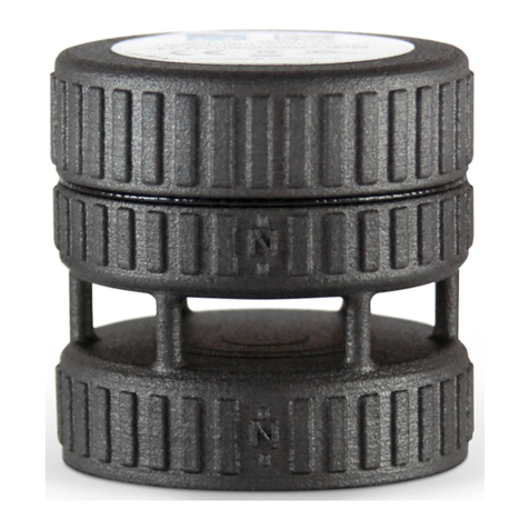
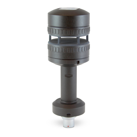
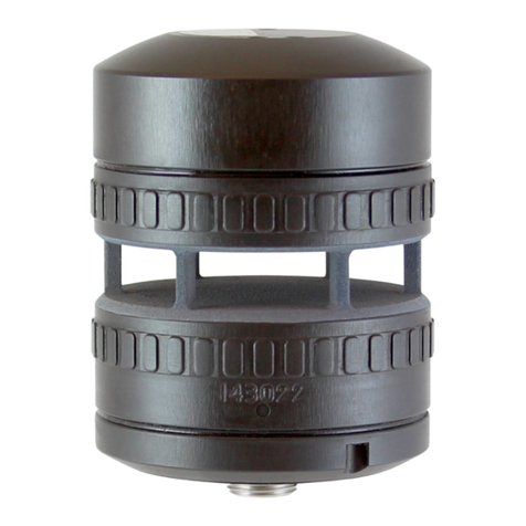
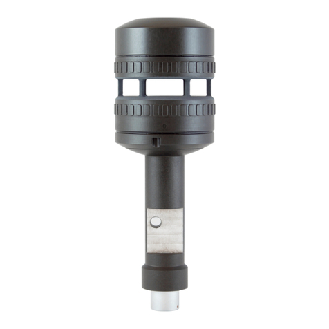
FT Technologies acures FT742-SM User manual

1 FT742-SM (RS422 & RS485) Sensors –User Manual
FT TECHNOLOGIES LTD.
SUNBURY HOUSE
BROOKLANDS CLOSE
SUNBURY-ON-THAMES
MIDDLESEX TW16 7DX
TEL: +44 (0)20 8943 0801
FAX: +44 (0)20 8943 3283
WEB: www.fttechnologies.com
E-MAIL: info@fttechnologies.com
A4281-2-EN
August 2017
The FT and Acu-Res logos are registered trademarks of FT Technologies Ltd.
Copyright © 2017 FT Technologies Ltd. All rights reserved.
FT742-SM –Digital Wind Sensor User Manual
Surface-Mounted - Digital RS422 & RS485 options

2 FT742-SM (RS422 & RS485) Sensors –User Manual
Contents
Product Symbols....................................................................................................... 4
Safety Instructions .................................................................................................... 5
Consignes de sécurité.............................................................................................. 6
1INTRODUCTION.................................................................................................. 7
1.1 Product Overview .............................................................................................................7
1.2 Build Versions and Labelling...........................................................................................7
1.3 Scope of Use.....................................................................................................................7
1.4 Disclaimer .........................................................................................................................8
2FUNCTIONAL DESCRIPTION ............................................................................9
2.1 Technical Performance.....................................................................................................9
2.2 Wind Speed Calibration..................................................................................................10
2.3 Wind Speed and Direction Filtering...............................................................................10
2.4 Electronically Offsetting the Wind Direction Datum.....................................................11
2.5 Compass & Declination Angle Operation......................................................................11
2.5.1 Compass Calibration ....................................................................................................11
2.6 Selective Filter Scheme..................................................................................................11
2.7 Error Detection................................................................................................................11
2.8 Overspeed Warning Scheme..........................................................................................12
2.9 Heater Setup....................................................................................................................12
2.10 Low Power Operation.....................................................................................................12
3MECHANICAL & ELECTRICAL INSTALLATION ............................................13
3.1 FT742-SM Sensors..........................................................................................................13
3.1.1 Mechanical & Electrical Integration...............................................................................13
3.1.2 Connector Details.........................................................................................................16
3.1.3 Lightning, Surge & EMI Protection................................................................................16
4SERVICE, CONFIGURATION & TESTING....................................................... 17
4.1 Inspection........................................................................................................................17
4.2 Fault Finding & Troubleshooting...................................................................................18
4.3 Returns............................................................................................................................18
5Evaluation .........................................................................................................19
5.1 Evaluation Pack ..............................................................................................................19
5.2 Acu-Test Software ..........................................................................................................19
5.3 FT058 & FT059 Evaluation Cables.................................................................................20
5.4 Software Installation.......................................................................................................21
6SENSOR COMMUNICATION............................................................................22

3 FT742-SM (RS422 & RS485) Sensors –User Manual
6.1 Introduction.....................................................................................................................22
6.2 RS422 & RS485 Protocol................................................................................................22
6.3 Configuring the Sensor ..................................................................................................25
6.4 Communication...............................................................................................................25
6.4.1 Conventions used in this manual ..................................................................................25
6.4.2 Data Transmission........................................................................................................26
6.4.3 Message Format...........................................................................................................26
6.4.4 Listener and Talker Identifiers.......................................................................................27
6.4.5 Calculating the Message Checksum.............................................................................27
6.4.6 Disabling the Checksum ...............................................................................................27
7PARAMETER SETTINGS.................................................................................. 29
7.1 Command Types.............................................................................................................29
7.1.1 Set Commands.............................................................................................................29
7.1.2 Query Commands.........................................................................................................30
7.2 User Calibration Table....................................................................................................31
7.3 Timing Constraints .........................................................................................................32
7.4 Command Parameters....................................................................................................33
7.4.1 BR: Set or Query the Serial Interface Baud Rate ..........................................................33
7.4.2 CF: Set or Query the Wind Compass Settings ..............................................................34
7.4.3 CU: Set or Query the Continuous Update Setting .........................................................36
7.4.4 DF: Set or Query the Wind Velocity Data Format..........................................................37
7.4.5 DG: Query the Run-time Counter..................................................................................38
7.4.6 DL: Set or Query the Command Delay Interval.............................................................39
7.4.7 ER: Query or Reset the Error Report ............................................................................40
7.4.8 FL.1: General Filter Settings.........................................................................................41
7.4.9 FL.2: Set or Query Filter Lengths..................................................................................42
7.4.10 FL.3: Set or Query the Selective Filter......................................................................43
7.4.11 HT.1: General Heater Settings.................................................................................44
7.4.12 HT.2: Delay Heater Settings....................................................................................45
7.4.13 ID: Set or Query the Listener & Talker Identifiers......................................................46
7.4.14 MM: Reset or Query the Min/Max Recorded Wind Speed.........................................47
7.4.15 OS: Overspeed Warning Scheme............................................................................48
7.4.16 PR: Query the Parameter Report..............................................................................49
7.4.17 RS: Reset the Sensor...............................................................................................50
7.4.18 SN: Query the Serial Number and Platform Version .................................................51
7.4.19 SV: Query the Software Version...............................................................................52
7.4.20 UC.1: General User Calibration Settings ..................................................................53
7.4.21 UC.2: Clear User Calibration Table Record ..............................................................54
7.4.22 UC.3: Set User Calibration Table Record .................................................................55
7.4.23 UC.4: Save and Read User Calibration Table...........................................................56
7.4.24 UC.5: Set & Query User Calibration Table Label ......................................................57
7.4.25 US: Set or Query Saved Parameters........................................................................58
7.4.26 WV Polar: Query the Wind Velocity Reading ............................................................60
7.4.27 WV NMEA: Query the Wind Velocity Reading ..........................................................61

4 FT742-SM (RS422 & RS485) Sensors –User Manual
Product Symbols
The following symbols may be used upon the product and within the manual.
Meaning / Description
Symbol
Signification / Description
Warning/ Caution
An appropriate safety instruction should be
followed or caution to a potential hazard
exists
Avertissement / Attention
Une instruction de sécurité doit être
suivie ou attention portée à un
danger potentiel qui existe.
DC Current only
Equipment operates under Direct Current
(DC) supply only.
Courant continu uniquement
L'équipement fonctionne sous une
alimentation en courant continu (CC)
uniquement.
Recognized Component
Sensors marked with the ETL label indicate
that the product conforms to UL Standard
61010-1 and is certified to CSA Standard
C22.2 No. 61010-1.
4000105
Composant Reconnu
Les capteurs marqués avec
l’étiquette ETL indiquent que le
produit est conforme à la norme UL
61010-01 et est certifié à la norme
CSA22.2 61010-01.
Product Disposal
In accordance with European directive
2012/19/EU on Waste Electrical and
Electronic Equipment (WEEE), these
product components must be recycled. This
should be done by returning the product to
FT Technologies or by using an appropriate
waste disposal company. This product
should not be disposed of in general waste
of landfill. This product complies with the
RoHS2 (2011/65/EU) directive.
Élimination du produit
Conformément à la directive
européenne 2012/19/EU relative aux
déchets d'équipements électriques et
électroniques (DEEE), ces
composants du produit doivent être
recyclés. Cela doit être fait par le
retour du produit à FT Technologies
ou en utilisant une entreprise
d'élimination de déchets. Ce produit
ne doit pas être éliminé avec les
ordures ménagères ou en décharge.
Ce produit est conforme à la
directive RoHS2 (2011/65/EU).
CE Mark
The EU Declaration of Conformity
complies with the essential requirements
of the following applicable EMC Directive
2014/30/EU, and carries the CE Marking
accordingly.
Marquage CE
Déclaration de conformité CE de la
compatibilité électromagnétique
(EMC) et marquage CE
conformément à la directive CE
2014/30/EU.

5 FT742-SM (RS422 & RS485) Sensors –User Manual
Safety Instructions
English
To ensure the safe installation and operation of this product the equipment must be installed and
integrated:
oUsing suitably qualified and trained personnel
oIn accordance with any regional electrical codes
oIn accordance with the instructions set out in this manual, observing all information, warnings
and instructions
oIn accordance with any other instructions or guidance FT Technologies provide
To ensure that the product remains compliant with the electrical safety requirements of the UL / CSA
61010-1 Standards it must be;
oConnected to an appropriately approved isolated power supply (for example UL/CSA IEC
60950-1:2005 + A1:2009 + A2:2013) rated 6-30VDC and be current limited (2.5A Maximum)
oProtected by UL 1449 listed surge protection devices
oConnected with an approved interface cable (for example UL/ CSA recognised AWM style
21198, rated 300V, 80°C)
The equipment must only be operated within the range of the specified technical data and used for the
purposes for which it was designed.
The equipment should always be transported in packaging which is appropriate, that will prevent any
accidental damage from occurring.
Always ensure that any failures or errors from the product cannot cause any damage to any other
equipment or property or cause any other consequential effects.

6 FT742-SM (RS422 & RS485) Sensors –User Manual
Consignes de sécurité
Français
Pour assurer la sécurité de l'installation et le fonctionnement de ce produit, l'équipement doit être
installé et intégré :
oÀ l'aide de personnel qualifié et formé
oConformément à tous les codes électriques régionaux
oConformément aux instructions figurant dans ce manuel et en observant toutes les
informations, avertissements et instructions
oConformément à d'autres instructions ou directives que FT Technologies fournit
Pour garantir que le produit reste compatible avec les exigences de sécurité électrique de l'UL/CSA
61010-1 normes, l'équipement doit être :
oConnecté à une alimentation agrée convenablement isolée (par exemple UL/CSA IEC 60950-
1:2005 + A1:2009 + A2:2013) de tension nominale 6-30 VCC et avec courant limité (2.5 A
max)
oProtégé par des dispositifs de protection UL 1449 contre les surtensions
oConnecté avec un câble d'interface (par exemple UL/CSA reconnu AWM style 21198, de
valeur nominale 300 V, 80°C)
L'équipement doit être utilisé uniquement dans la plage des données techniques spécifiées et utilisé
aux fins pour lesquelles il a été conçu.
L'équipement doit toujours être transporté dans un emballage qui est approprié, qui permettra d'éviter
qu'un quelconque dommage accidentel ne survienne.
En toutes circonstances, garantir que les défaillances ou les erreurs du produit ne puissent pas causer
des dommages à d'autres équipements ou autres biens ou provoquer d'autres effets indirects.

Section 1 Introduction
7 FT742-SM (RS422 & RS485) Sensors –User Manual
1 INTRODUCTION
1.1 Product Overview
The FT742-SM is a solid-state ultrasonic wind sensor, using a patented Acoustic Resonance airflow
sensing technique to measure accurately both wind speed and direction. The sensors have been
specifically designed to operate in harsh environments including offshore and ice-prone areas. The
wind sensor has no moving parts to degrade or wear and is designed for applications requiring high
reliability. This helps reduce costly down-time and unscheduled maintenance visits.
Mounting and aligning the sensor is very simple. A wind datum feature mark can be used to align the
sensor to a reference point, while the integrated compass allows reference to magnetic North. For
operation in ice-prone areas, the FT742 is fitted with a thermostatically controlled all-body heating
system. A two-element heater is used to ensure heat is evenly distributed over the entire surface
area.
The FT742-SM allows either RS422 (full-duplex) or RS485 (half-duplex) communication outputs, this
communication setting is programmed at the factory and cannot be modified by the user.
1.2 Build Versions and Labelling
Figure 1 shows how to identify the sensor platform version and individual serial number, depending on
the attached main labels:
Additional labels may be attached.
Figure 1: Main Sensor Labels
1.3 Scope of Use
The sensor is designed, manufactured and optimised for high availability.
No promise in part or full can be given to guarantee a sensor’s continuous operation, as exceptional
circumstances can occur that may result in the failure of the output from a sensor. Exceptional
circumstances can include:
Poor installation
Inadequate inspection
Power supply failures
Poor quality electrical connections
Lightning exposure
Problematic environmental conditions or combination of conditions
Physical Damage

Section 1 Introduction
8 FT742-SM (RS422 & RS485) Sensors –User Manual
Typically higher levels of wind speed and wind direction data availability are achieved through the use
of an additional FT sensor or alternative sensor. Control strategies or algorithms, which compensate in
whole or in part, for any temporary interruption of data from individual sensors should also be applied.
The choice and implementation of such methods is entirely the Purchaser’s responsibility.
1.4 Disclaimer
There are no warranties, representations or conditions, expressed or implied of any kind given in this
manual for any particular design application. The Purchaser should independently undertake sufficient
testing to confirm validity and suitability of any design. The Purchaser assumes all risks and liability in
conjunction with the use of the information given.
Any warranty given by FT Technologies in respect of the Equipment is conditional upon the sensor
being handled, installed, integrated and operated in accordance within the guidelines given in this
manual.
FT Technologies can take no responsibility for the effectiveness of any sensor lightning protection
scheme implemented. The wind sensor has passed a wide range of EMC tests but FT Technologies
does not warrant the sensor to survive lightning strikes.
Information supplied by FT Technologies Ltd. shall not be construed as permission to license to operate
under, or recommendation to infringe any existing or pending patent, patent applications or trademarks.

Section 2 Functional Description
9 FT742-SM (RS422 & RS485) Sensors –User Manual
2 FUNCTIONAL DESCRIPTION
2.1 Technical Performance
Sensor Performance1 & 2
Measurement Principle Acoustic Resonance (compensated against variations in temperature,
pressure and humidity)
Wind Speed Measurement
Range 0-75m/s
Resolution 0.1m/s
Accuracy ±0.3m/s (0-16m/s)
±2% (16m/s-40m/s)
±4% (40m/s-75m/s)
Wind Direction Measurement
Range 0 to 360°
Sensor Accuracy 4RMS
Compass Accuracy 5RMS
Resolution 1
Environment
Temperature Range -40 to +85C (operating and storage)
Humidity 0-100%
Altitude 0-4000m
Data I/O
Interface RS422 (full-duplex) or RS485 (half-duplex). The communications
interface option is programmed at the factory.
Format ASCII, polled or Continuous Update modes (CU on RS422 only)
Data Update Rate Up to 10 measurements per second (10Hz)
Power Requirements3, 4 & 5
Supply Voltage 24VDC nominal (6-30VDC range). A minimum of 9VDC is required
for heater operation
Sensor Current (Heater off) 25mA nominal (29mA with compass enabled)
Heater Current (Heater on)6 Up to 2A + nominal
Physical
Weight 252g
Material Aluminium alloy (external body hard anodised)
I/O Connector 8-way M12 connector
Mounting Method Surface-Mount with compressed O-ring/screw fit
Notes:
1.All specifications subject to change without notice.
2.Specifications calculated with the default settings and filters enabled.
3.See safety instruction requirements (page 5 and 6).
4.The heater set-point temperature can be configured by the user. Modifications to the heater current
limit and under-voltage limit are not permitted on the FT742-SM range, for further details contact FT
Technologies.
5.The current draw from the heater will depend on the environmental cooling and the temperature
setpoint. The sensor is limited to 2A4 nominal by default. The maximum power is 60W (30V & 2A).
6.A suitable PSU capable of providing up to 2.5A maximum is recommended.

Section 2 Functional Description
10 FT742-SM (RS422 & RS485) Sensors –User Manual
2.2 Wind Speed Calibration
The wind sensor is calibrated in our wind tunnels before dispatch. As the sensor has no moving parts, there is
no need to recalibrate a sensor over its lifetime as no measurement degradation will occur. The sensor’s
compact strong monolithic shape is designed to prevent accidental transducer movement or damage. FT
Technologies’calibration procedure and wind tunnels are designed to give a calibration profile that is within the
accuracy limits set in the product technical specification (see Section 2.1). Periodically the accuracy of FT’s
wind tunnels are compared with the accuracy of an independent wind tunnel to ensure that no drift has
occurred.
In exceptional circumstances users may wish to apply additional calibration factors. The sensors have an option
to set a User Calibration Table, which can modify the wind sensor’s wind speed output (see Section 7.4.20).
The User Calibration Table can be programmed with up to 64 correction factors which are maintained in non-
volatile memory. When enabled, the uncorrected wind speed output is adjusted according to the stored User
Calibration Table records using linear interpolation. The adjustments are applied to wind speed readings
regardless of wind direction.
2.3 Wind Speed and Direction Filtering
It is important that the system does not rely exclusively on a single wind reading for any control decision. A
single reading may be inaccurate due to measurement error, turbulence, corruption or interference. It is
recommended that an average of wind readings is used. In addition if 100% data availability is required then a
second FT sensor or alternative wind sensors should be fitted in addition.
The sensor has optional internal filtering available. This is a digital finite impulse response (FIR) filter, which
works by calculating the moving average of a fixed number of previous readings. If filtering is being applied
externally, the sensor’s output filters can be disabled. If filtering inside the sensor is preferred, the length of the
averaging for both wind speed and direction can be independently set (See Sections 7.4.8 and 7.4.9).
Figure 2: Examples of FIR Filtering
It is recommended to use average readings to reduce the effects of air turbulence.

Section 2 Functional Description
11 FT742-SM (RS422 & RS485) Sensors –User Manual
2.4 Electronically Offsetting the Wind Direction Datum
For applications where the compass is not being used, the wind direction datum can be ‘electronically’ rotated
using the CF command. The declination angle function normally used in conjunction with the compass function
can be used to realign the datum position anywhere in the range 0-359.9°.
See Section 7.4.2 for further details.
2.5 Compass & Declination Angle Operation
The FT742-SM is fitted with a solid-state electronic compass so that the wind direction can be measured relative
to magnetic North. The wind direction can be measured either relative to magnetic North, or by programming
the sensor with the geographical location declination angle, relative to true North. The compass function can
also be disabled if required so that the wind direction is measured relative to the datum mark on the wind sensor
body (as per Figure 4). The compass heading can also be read back at any time using the CF command. See
Section 7.4.2 for full details of the CF command. Both the Polar format (P) and NMEA 0183 format (N) outputs
provide wind direction data relative to North (if the compass function is enabled). The NMEA 0183 message
also has a field that indicates whether the compass module is enabled or disabled.
The effects of fixed local magnetic fields (i.e. those caused by magnetised ferrous material close to the
compass) can be compensated for by performing an in situ compass calibration. It is important that the
calibration is performed with the FT742-SM mounted in its final position within the host system. The calibration
can only compensate for fixed magnetic fields generated by the host system. Varying fields caused, for
example, by ferrous objects passing near the FT742-SM (say by a car or truck) or high current electric circuits
will not be corrected. Should the magnetic signature of the host system change significantly (because
component parts have been added or removed), then a recalibration may be required.
2.5.1 Compass Calibration
Compass calibration should be performed away from any external stray magnetic fields. To calibrate the FT742-
SM compass proceed as follows:
1) Mount the FT742-SM in its final position within the host system
2) Ensure the compass is enabled (send the CFE ‘enable compass’ command, see Section 7.4.2).
3) Send the CFC ‘enable calibration’ command (see Section 7.4.2). Important: No further commands should be
sent to the FT702LM after the CFC command has been sent.
4) Slowly rotate the host system 1 complete revolution in the horizontal plane. The revolution should take
between 40 and 60 seconds.
5) To complete the calibration send the CFE ‘enable compass’ command (see Section 7.4.2).
6) Store the new calibration Parameters in the compass module using the CFMS command. The save
command, for example $01,CFMS*//<cr><lf>, will save the new compass calibration parameters calculated
during the calibration process to the Interface Board Flash memory. This command is required.
2.6 Selective Filter Scheme
In addition to the averaging filter described in Section 2.3, the sensor has a feature called the Selective Filter.
The scheme allows the user to set a “validity period”, during which the sensor will exclude invalid readings from
entering the averaging filter. The output will freeze on the last previous “good” reading and only raise an error
flag once the number of bad readings exceeds the validity period. This scheme can be enabled by factory
configuration or by using the FL command (see Section 7.4.10). The filter is turned off by default to match
legacy behaviour.
2.7 Error Detection
The sensor has a self-checking mechanism which can detect if a reading is invalid. On very rare occasions
where an invalid reading may have been detected, this is signalled to the computer or data logger by setting an
error flag character within the wind velocity output message (see Sections 7.4.26 and 7.4.27).

Section 2 Functional Description
12 FT742-SM (RS422 & RS485) Sensors –User Manual
When an error is detected, the error flag character is set to a value of: 1.
Note: An optional Overspeed Warning Scheme can be enabled (but is disabled by default). See Section 2.8 for
further details.
It is important that error flags are not ignored. Data associated with an error flag should not be processed as
valid wind data. The system should be capable of riding through rare periods when data may be temporarily
unavailable. If errors are ongoing (more than several seconds), a reset of the sensor should be applied (see
Section 7.4.17 for instructions on sending an RSU command).
It is recommended that errors are monitored and logged. If the frequency of errors has recently increased, then
inspection of the sensor for physical blockages may be required (see Section 4.1).
2.8 Overspeed Warning Scheme
During periods where the sensor detects wind speed beyond the rating of the sensor, the sensor will (by default)
indicate a general error flag status.
An additional overspeed warning scheme can be enabled: if an overspeed condition is detected (above the
highest speed rating), the error flag character will be set to: 2 (see Sections 7.4.26 and 7.4.27) unless a general
error condition is also detected and the flag will be set to 1.
To comply with legacy behaviour, this scheme is disabled by default.
The Overspeed Warning Scheme can be enabled by software commands (see Section 7.4.15), via the Acu Vis
PC software program or enabled in the factory before despatch.
2.9 Heater Setup
The sensor is fitted with an integral two-element distributed heater that can be used to prevent icing-up of the
sensor in freezing temperatures. The heater is controlled automatically by the sensor using a user
programmable ‘set point’ temperature. The sensor uses a control scheme which dynamically changes the
current supplied to each individual heater element in order to maintain the programmed set point temperature.
It is important to consider the resistive losses in the cable and rate the cable appropriately. In general, power
losses in the cable should be minimised in order to maximise the available heating power to the sensor. A
heater setpoint temperature of >30°C is recommended for most applications. To change the heater set point or
to disable the heater use the Acu-Vis test software or the HT software command (see Section 7.4.11).
Since the heater circuit is thermostatically controlled, the actual power being drawn from the supply will depend
on the voltage supplied, the programmed set-point and the environmental conditions (i.e. ambient temperature,
wind speed, precipitation etc.). The maximum current that the sensor can consume is limited to 2A (nominal) by
default. The power supply must be rated to provide the maximum heater power (60W @ 30V and 2A) that the
sensor can consume. The heater requires a minimum of 9VDC for operation (contact FT technologies for further
details on the minimum heater voltage limit).
For applications requiring higher power/current ratings or modification of heater performance (including cold
environment operation) please contact the FT technical support teams for further information.
Caution - Modifications to the heater current limit are not permitted on the FT742-SM. Cables must be suitably
rated for the application. Contact FT Technologies for further information.
If the sensor is powered up and there is a possibility it has become iced, it is recommended that the sensor is
allowed to heat up for 30 minutes, followed by a User Reset Command (see Section 7.4.17) to permit the
sensor to initialise correctly without ice blockage.
2.10 Low Power Operation
The sensor is designed for typical operation at 24VDC, operating at a range of 6-30VDC, however the heater
will deactivate below 9VDC. Lower voltages reduce the overall power consumption and heater performance.
For further advice on power and heater management strategies, see Sections 7.4.11 and 7.4.12.

Section 3 Mechanical & Electrical Installation
13 FT742-SM (RS422 & RS485) Sensors –User Manual
3 MECHANICAL & ELECTRICAL INSTALLATION
The FT742-SM has a surface-mounted design for installation on flat surfaces. The product range is optimised
for cost-efficient operation including the use of standard off-the-shelf cables.
The sensor uses an 8-way M12 connector. IP66 and IP67 ratings are achieved through the use of a
compression fit O-ring seal.
Ensure the airflow into the sensor is not obstructed or influenced by nearby objects.
See safety instruction requirements on pages 5 and 6.
The wind sensor installation must be properly designed to ensure the correct
operation of the sensor. This section is for guidance only. It is the responsibility of
the designer and installer to ensure that the installation and its design is fit for
purpose. Please see Disclaimer Section 1.4.
3.1 FT742-SM Sensors
3.1.1 Mechanical & Electrical Integration
The sensor measures the effects of airflow through the sensor cavity on a resonating acoustic signal. The
sensor can be rotated to ensure alignment with a standard reference, typically Magnetic North, or the integrated
compass can calculate this automatically.
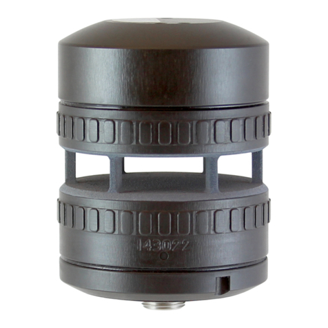
Figure 3: The FT742-SM Sensor
The mounting surface should be smooth and flat. Textured, uneven or damaged surfaces will reduce the quality
of the water ingress protection.

Section 3 Mechanical & Electrical Installation
14 FT742-SM (RS422 & RS485) Sensors –User Manual

Section 3 Mechanical & Electrical Installation
15 FT742-SM (RS422 & RS485) Sensors –User Manual
Figure 4: Outline Dimensions, Assembly & Wind Direction Reference (Compass Disabled)
Figure 5: Sensor Base Dimensions
Figure 5 displays the location of the O-ring groove (FT O-ring part number FT029, manufacturer part number:
2-127 O-Ring EPDM 70 Shore). One O-ring is supplied with new sensors. The use of lubricant on the O-ring will
depend on the material selection.

Section 3 Mechanical & Electrical Installation
16 FT742-SM (RS422 & RS485) Sensors –User Manual
The O-ring compression fit is secured using 5x M3 fixings. The internal thread depth is 4.5mm, the length of
fixings should be determined taking into account the thickness of the mounting surface. Regular condition
monitoring of the sealing interface is recommended.
Caution –Excessive length or tightening of the M3 screw may cause damage to the sensor thread.
3.1.2 Connector Details
All electrical connections are made to the digital sensor via an 8-way multi-pole connector located in the base
of the wind sensor housing. The connector pin designations are shown in Figure 6. The connector conforms to
IEC 61076-2-101.
Pin
RS422
RS485
FT009 Wire Colour*
1
0V
0V
Brown
2
6-30V
6-30V
White
3
TX Data A
N/C
Blue
4
RX Data A
Data A
Black
5
TX Data B
N/C
Grey
6
RX Data B
Data B
Pink
7
N/C
N/C
Violet
8
N/C
N/C
Orange
*Caution: Wire colours apply only to FT supplied FT009 cables. Other
cables may use different colour schemes, contact FT technologies for
further information.
Figure 6: Sensor Connector Pin
The FT742-SM sensor uses a M12 8-way male connector (ERNI Production GmbH, part number 464676).
Finished cable assemblies are available off-the-shelf as well as custom manufacture. The FT742-SM can use
up to 2A with the heater enabled, it is necessary to confirm all cables used are suitably rated for the operational
environment.
Care must be taken to ensure that the cable is suitable for the environment it will be used in and is adequately
rated and approved, for example AWM Style 21198. In an area with a moderate or severe lightning strike
exposure the cable may not provide sufficient EMI protection. In this case the cable will require further shielding,
for example being enclosed in a grounded metal pipe or conduit, or the use of sensors with a higher grade of
protection (for example the FT742-PM range).
The part FT009 is a 1.5m cable that can be used with the FT742-SM.
3.1.3 Lightning, Surge & EMI Protection
It is important to install the sensor and cabling with appropriate protection against lightning and other sources of
electromagnetic interference, in order to maximise its chance of survival and continued operation during and
after exposure.
The FT742-SM sensor is specifically designed for meteorological applications where the risk of lightning
exposure (indirect) is low.
All connections from the wind sensor to any data acquisition equipment and power supply should run through
suitable Surge Protection Devices (SPDs). This will suppress any unwanted overvoltage transients present on
the signal or power lines. The surge suppression devices are to be UL 1449 listed.
For areas where there is a high risk of lightning exposure (but still indirect) we would recommend the use of the
Pipe-Mount (PM) range of sensors. In such applications, the sensor body should be well grounded and the PM
variant of sensor is a more suitable solution. See the PM wind sensor User Manual for more details on this, or
contact FT Technologies for more information.

Section 4 Service, Configuration & Testing
17 FT742-SM (RS422 & RS485) Sensors –User Manual
4 SERVICE, CONFIGURATION & TESTING
4.1 Inspection
The following checks are required to identify any signs of corrosion or damage on the sensor which may hinder
its performance. It is recommended that these checks be carried out annually.
Mechanical damage: Check the sensor body for signs of damage, paying particular attention to the seals. Also
inspect for signs of lightning damage which may appear as burns or scorch marks (or burnt smells). If damage
has occurred replace the sensor immediately. Inspect the hydrophobic cavity coating for wear, corrosion and
damage. Check the O-ring seal and fixings are in good condition, replace them if necessary for long-term
protection.
Corrosion: Inspect the mounting surfaces of the sensor for signs of corrosion. If corrosion is present on any
surface, it should be removed using an abrasive cloth. Before reinstalling the sensor, electrical joint compound
should be applied to the sensor’s mounting flat (see Section 3). Check that any fixings and O-rings are in good
condition with no signs of corrosion and tighten as necessary. If corrosion is present replace with parts of the
appropriate finish (see Section 3).
Interconnection cable: Inspect the condition of the cable. If it has become frayed or damaged it should be
replaced. Intermittent cable faults may not be visible and may show up as data errors. Check the intended
network component values (termination resistors etc.).
Connector protective sleeve: If cable protection is used, check for any signs of damage or degradation.
Cleaning: The measurement cavity has a special hydrophobic coating (water repelling) which helps to prevent
water building up. When water enters the measurement cavity the surface helps to wash away dust and debris
which may have settled. If any debris is present this can be removed by gently rinsing the measurement cavity
surface with distilled water using a laboratory wash bottle or similar. Please note excess water droplets can be
removed by lightly blowing or shaking the sensor.

Section 4 Service, Configuration & Testing
18 FT742-SM (RS422 & RS485) Sensors –User Manual
Do not scrape or scratch the surfaces whilst rinsing. Under no circumstances should objects be inserted
inside the measurement cavity, as this can cause irreparable damage. If the coating has been damaged then it
may need to be reapplied. The body of the sensor can be washed if required using the same method as
described above. Whilst washing the sensor care must be taken not to get water in the breather hole or into the
connector at the base of the sensor.
Do not use cleaning chemicals to clean the sensor. If washing a nearby item protect the sensor with a suitable
cover. Ensure the cover is removed before re-enabling the wind data survey.
4.2 Fault Finding & Troubleshooting
To determine whether a sensor has a fault carry out the following steps:
Follow the inspection procedure above to identify signs of physical damage.
Remove any objects or insects lining the cavity or blocking the airflow.
Reset the sensor (RSU command or power-cycle).
If there are signs of physical damage and/or the sensor is failing to communicate properly, it should be replaced.
Sensors may be returned to FT Technologies for further analysis if required (see Section 4.3).
Warning –The sensor contains no user serviceable components. Do not attempt
disassembly as damage may result and product warranties will be invalidated.
During extreme weather conditions there may be periods where data is temporarily unavailable. However there
are ways to mitigate against these affects. The following steps should be taken to ensure the highest levels of
data availability from the sensor:
Check that the wind sensor data and status flag errors are being processed as per the advice in
Sections 7.4.26 and 7.4.27.
Ensure that any installed lightning and EMI protection (see Section 3) is in good condition and any cable
shielding is terminated at both ends. All mating surfaces must be free of paint and corrosion.
Check that the measurement cavity’s special coating is in a satisfactory condition and no debris is
present. Debris can be blown out or washed out with distilled water spray.
Please contact FT Technologies for further information and advice if required.
4.3 Returns
If a sensor appears to be faulty, compile a detailed fault description for each sensor, then contact FT
Technologies to request a Returns Materials Authorisation (RMA) form. Please complete the form and return as
instructed. Returns cannot be accepted without prior approval via this authorisation form.
Units damaged by lightning or disassembled by the customer cannot typically be repaired, however an
inspection fee may still apply.

Section 4 Service, Configuration & Testing
19 FT742-SM (RS422 & RS485) Sensors –User Manual
5 Evaluation
5.1 Evaluation Pack
To help users carry out a test bench assessment of the FT742-SM sensors, FT Technologies sells two USB test
cables allowing connection to the RS422 and RS485 communication variants via USB PC connection.
Acu-Test Evaluation Pack –This kit includes a CD with user manuals, the Acu-Vis software installation files and
a USB test cable. The test cables require a 6-30VDC external power supply capable of providing up to 2A.
Alternatively the FT062 power supply can be used (a regional C13-style adaptor is necessary for mains
connection).
The FT058 is used for RS422 sensors.
The FT059 is used for RS485 sensors.
The user can view the communication settings, configuration information, serial number and product type, with
the ability to modify a limited number of settings (for example enabling/disabling the heater, or changing the
heater set-point).
Caution: FT742-SM sensors should only be connected to the Acu-Vis PC test program.
Warning: Live connection/disconnection of the power and/or sensors during live operation, or miswiring
of the power leads could damage the equipment and is not covered by FT’s standard warranty terms
5.2 Acu-Test Software
The Acu-Vis software automatically detects the USB test cable and wind sensor when plugged in and power
provided to the sensor. The program will detect the wind sensor as long as it is powered up and working. The
dials then show the real time wind speed and direction from the wind sensor as shown in
Figure 7: Acu-Vis Live Display –Home Page (example)
1. “Wind Reading” Tab –live sensor readings
2. “Heater Settings” Tab
3. Wind Speed Dial
4. Wind Direction Dial
5. Wind Speed Dial Range Selection
6. Wind Speed (numeric)
7. Wind Direction (numeric)
8. Current Heater Set-point
9. Sensor Communication Baud Rate
10. Software Version on Sensor
11. Sensor Response Delay –user defined
12. Product Name –of attached sensor
13. Product Version –of attached sensor
14. Serial Number –of attached sensor
15. Cable Name –type of attached cable
16. Serial Number –of attached cable

Section 4 Service, Configuration & Testing
20 FT742-SM (RS422 & RS485) Sensors –User Manual
The program also shows the communication settings that the sensor is using as well as its software version and
serial number.
The Heater Control tab can be used to monitor the sensor’s heaters and to change the sensor’s heater set point
temperature as shown in Figure 8.
The Acu-Vis software will work on a PC running Microsoft® Windows XP, Windows Vista, 7, 8 and 10.
Figure 8: Acu-Vis Heater Controls
17. Heater Set-point –Currently on sensor
18. Sensor Temperature –Sensors internal
temperature
19. Heater Duty Cycle –Heater Duty Cycle (%)
20. Heater Power –Estimate of heater power
21. Select to enable/disable sensor heaters
22. New Desired Heater Set-point
23. Upload settings to sensor
24. Temperature gauge
5.3 FT058 & FT059 Evaluation Cables
The FT742-SM can be tested by connecting it to a computer using the relevant FT USB cable and a power
supply. Figure 9 shows how the Evaluation Pack can be quickly set up to evaluate the sensor using Acu-Vis.
Figure 9: Evaluation Cable
This equipment can only be used to test the FT742-SM range of digital output wind sensors
Use a bench power supply unit, 6-30 VDC (up to 2A), rechargeable Battery or +24 VDC Laptop charger,
or the FT062 PSU (with regional C13-style mains adaptor)
Other manuals for acures FT742-SM
1
Table of contents
Other FT Technologies Accessories manuals

FT Technologies
FT Technologies FT742-D-SM User manual

FT Technologies
FT Technologies FT702LT/D User manual

FT Technologies
FT Technologies FT205EV User manual

FT Technologies
FT Technologies FT742 User manual

FT Technologies
FT Technologies acures FT742-SM User manual

FT Technologies
FT Technologies acures FT722 User manual