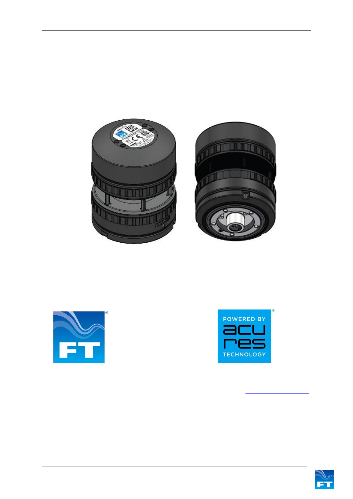
3 FT742-SM (RS422 & RS485) Sensors –User Manual
6SENSOR COMMUNICATION...........................................................................30
6.1 Introduction........................................................................................................................30
6.2 RS422 & RS485 Protocol...................................................................................................30
6.3 Configuring the Sensor.....................................................................................................33
6.4 Communication..................................................................................................................33
6.4.1 Conventions used in this manual ....................................................................................33
6.4.2 Data Transmission ..........................................................................................................34
6.4.3 Message Format..............................................................................................................34
6.4.4 Listener and Talker Identifiers.........................................................................................35
6.4.5 Calculating the Message Checksum...............................................................................35
6.4.6 Disabling the Checksum..................................................................................................35
7PARAMETER SETTINGS ................................................................................37
7.1 Command Types................................................................................................................37
7.1.1 Set Commands................................................................................................................37
7.1.2 Query Commands ...........................................................................................................38
7.2 User Calibration Table.......................................................................................................39
7.3 Timing Constraints............................................................................................................40
7.4 Command Parameters.......................................................................................................41
7.4.1 AM: Set or Query Anemometer Mount Orientation .........................................................41
7.4.2 AT.1: Query the Acoustic Temperature...........................................................................42
7.4.3 AT.2: Set or Query the Acoustic Temperature Units.......................................................43
7.4.4 AT.3 Set or Query the Acoustic Temperature Filter Length............................................44
7.4.5 BR: Set or Query the Serial Interface Baud Rate............................................................45
7.4.6 CF: Set or Query the Wind Compass Settings................................................................46
7.4.7 CU: Set or Query the Continuous Update Setting...........................................................48
7.4.8 DF: Set or Query the Wind Velocity Data Format ...........................................................50
7.4.9 DG: Query the Run-time Counter....................................................................................52
7.4.10 DL: Set or Query the Command Delay Interval ..........................................................53
7.4.11 ER: Query or Reset the Error Report..........................................................................54
7.4.12 FL.1: Set or Query General Filter Settings .................................................................55
7.4.13 FL.2: Set or Query Filter Lengths................................................................................56
7.4.14 FL.3: Set or Query the Selective Filter........................................................................57
7.4.15 HT.1: Set or Query General Heater Settings..............................................................58
7.4.16 HT.2: Set or Query Delay Heater Settings..................................................................59
7.4.17 ID: Set or Query the Listener & Talker Identifiers.......................................................60
7.4.18 MM: Reset or Query the Min/Max Recorded Wind Speed..........................................61
7.4.19 OS: Set or Query Overspeed Warning Scheme........................................................62
7.4.20 RS: Reset the Sensor .................................................................................................63
7.4.21 SN: Query the Serial Number and Platform Version ..................................................64
7.4.22 SV: Query the Software Version.................................................................................65
7.4.23 UC.1: General User Calibration Settings....................................................................66
7.4.24 UC.2: Clear User Calibration Table Record................................................................67
7.4.25 UC.3: Set User Calibration Table Record...................................................................68
7.4.26 UC.4: Save and Read User Calibration Table............................................................69
7.4.27 UC.5: Set & Query User Calibration Table Label .......................................................70
7.4.28 US: Set or Query Saved Parameters..........................................................................71
7.4.29 WV Polar: Query the Wind Velocity Reading..............................................................73
7.4.30WV NMEA: Query the Wind Velocity Reading............................................................75