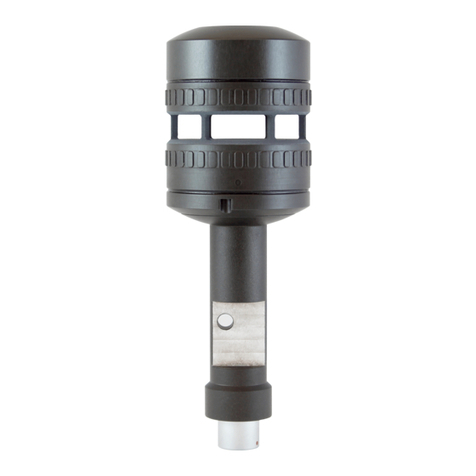
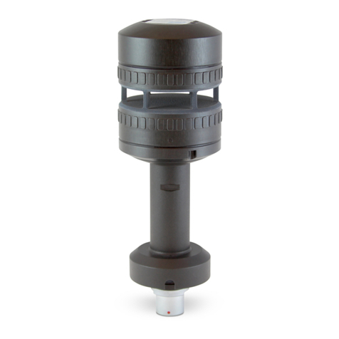
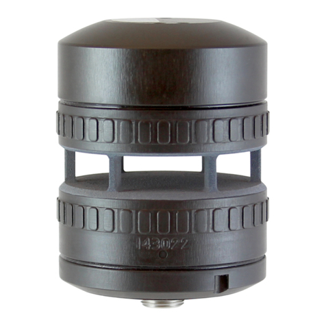
FT Technologies FT205EV User manual

A4171-2-EN (March 2020) Copyright © 2020 FT Technologies Ltd.
FT TECHNOLOGIES LTD.
SUNBURY HOUSE
BROOKLANDS CLOSE
SUNBURY-ON-THAMES
MIDDLESEX TW16 7DX
UNITED KINGDOM
TEL: +44 (0)20 8943 0801
FAX: +44 (0)20 8943 3283
WEB: www.fttechnologies.com
E-MAIL: info@fttechnologies.com
FT205EV™ – Digital Wind Sensor User Manual
Surface and Pole Mount Options
Digital RS422, RS485HD and UART options

2FT205EV Wind Sensors –User Manual
Contents
Contents....................................................................................................................2
Product Symbols......................................................................................................4
Safety Instructions...................................................................................................5
1INTRODUCTION................................................................................................. 6
1.1 Product Overview ................................................................................................................6
1.2 Build Versions and Labelling .............................................................................................6
1.3 Scope of Use........................................................................................................................7
1.4 Disclaimers...........................................................................................................................7
2FUNCTIONAL DESCRIPTION ...........................................................................8
2.1 Technical Performance .......................................................................................................8
2.2 Wind Speed Calibration ......................................................................................................9
2.3 Wind Speed and Direction Filtering...................................................................................9
2.4 Electronically Offsetting the Wind Direction Datum ......................................................10
2.5 Compass & Declination Angle Operation .......................................................................10
2.5.1 Compass Calibration.......................................................................................................10
2.6 Selective Filter Scheme.....................................................................................................10
2.7 Error Detection...................................................................................................................11
2.8 Overspeed Warning Scheme............................................................................................11
2.9 Acoustic Temperature.......................................................................................................11
3MECHANICAL & ELECTRICAL INSTALLATION............................................12
3.1 FT205EV Sensors ..............................................................................................................12
3.1.1 Mechanical & Electrical Integration .................................................................................12
3.1.2 Connector Details............................................................................................................18
3.1.3 Surge & EMI Protection...................................................................................................19
4SERVICE, CONFIGURATION & TESTING...................................................... 20
4.1 Inspection...........................................................................................................................20
4.2 Fault Finding & Troubleshooting.....................................................................................21
4.3 Returns ...............................................................................................................................21
4.4 Acu-Test Evaluation Kit ....................................................................................................22
4.4.1 Software Installation........................................................................................................23
4.4.2 Acu-Vis 2.0 Software Operation......................................................................................24
4.4.3 Command Line Terminal Programs (Including Tera Term) ............................................29
5SENSOR COMMUNICATION...........................................................................31
5.1 Introduction........................................................................................................................31
5.2 RS422 & RS485 Protocol...................................................................................................31
5.3 UART Protocol ...................................................................................................................34
5.4 Configuring the Sensor.....................................................................................................34

3FT205EV Wind Sensors –User Manual
5.5 Communication..................................................................................................................35
5.5.1 Conventions used in this manual ....................................................................................35
5.5.2 Data Transmission ..........................................................................................................36
5.5.3 Message Format..............................................................................................................36
5.5.4 Listener and Talker Identifiers.........................................................................................37
5.5.5 Calculating the Message Checksum...............................................................................37
5.5.6 Disabling the Checksum..................................................................................................37
6PARAMETER SETTINGS ................................................................................39
6.1 Command Types................................................................................................................39
6.1.1 Set Commands................................................................................................................39
6.1.2 Query Commands ...........................................................................................................40
6.2 User Calibration Table.......................................................................................................41
6.3 Timing Constraints............................................................................................................42
6.4 Command Parameters.......................................................................................................43
6.4.1 AM: Set or Query Anemometer Mount Orientation .........................................................43
6.4.2 AT.1: Query the Acoustic Temperature...........................................................................44
6.4.3 AT.2: Set or Query the Acoustic Temperature Units.......................................................45
6.4.4 AT.3 Set or Query the Acoustic Temperature Filter Length............................................46
6.4.5 BR: Set or Query the Serial Interface Baud Rate............................................................47
6.4.6 CF: Set or Query the Wind Compass Settings................................................................48
6.4.7 CI: Set or Query the Communication Interface (RS485, RS422, UART)........................50
6.4.8 CU: Set or Query the Continuous Update Setting...........................................................51
6.4.9 DF: Set or Query the Wind Velocity Data Format...........................................................52
6.4.10 DG: Query the Run-time Counter ...............................................................................54
6.4.11 DL: Set or Query the Command Delay Interval ..........................................................55
6.4.12 ER: Query or Reset the Error Report..........................................................................56
6.4.13 FL.1: Set or Query General Filter Settings .................................................................57
6.4.14 FL.2: Set or Query Filter Lengths................................................................................58
6.4.15 FL.3: Set or Query the Selective Filter........................................................................59
6.4.16 HT.1: Query Heater Settings......................................................................................60
6.4.17 ID: Set or Query the Listener & Talker Identifiers.......................................................61
6.4.18 MM: Reset or Query the Min/Max Recorded Wind Speed..........................................62
6.4.19 OS: Set or Query Overspeed Warning Scheme........................................................63
6.4.20 RS: Reset the Sensor .................................................................................................64
6.4.21 SN: Query the Serial Number and Platform Version ..................................................65
6.4.22 SV: Query the Software Version.................................................................................66
6.4.23 UC.1: Set or Query the General User Calibration Settings.........................................67
6.4.24 UC.2: Clear User Calibration Table Record................................................................68
6.4.25 UC.3: Set User Calibration Table Record...................................................................69
6.4.26 UC.4: Save and Read User Calibration Table............................................................70
6.4.27 UC.5: Set & Query User Calibration Table Label .......................................................71
6.4.28 US: Set or Query Saved Parameters..........................................................................72
6.4.29 WV Polar: Query the Wind Velocity Reading..............................................................74
6.4.30 WV NMEA: Query the Wind Velocity Reading............................................................76
4FT205EV Wind Sensors –User Manual
Product Symbols
The following symbols may be used upon the product and within the manual.
Meaning / Description
Symbol
Signification / Description
Warning/ Caution
An appropriate safety instruction should be
followed or caution to a potential hazard
exists
Avertissement / Attention
Une instruction de sécurité doit être
suivie ou attention portée à un
danger potentiel qui existe.
DC Current only
Equipment operates under Direct Current
(DC) supply only.
Courant continu uniquement
L'équipement fonctionne sous une
alimentation en courant continu (CC)
uniquement.
Product Disposal
In accordance with European directive
2012/19/EU on Waste Electrical and
Electronic Equipment (WEEE), these
product components must be recycled. This
should be done by returning the product to
FT Technologies or by using an appropriate
waste disposal company. This product
should not be disposed of in general waste
of landfill. This product complies with the
RoHS2 (2011/65/EU) directive.
Élimination du produit
Conformément à la directive
européenne 2012/19/EU relative aux
déchets d'équipements électriques et
électroniques (DEEE), ces
composants du produit doivent être
recyclés. Cela doit être fait par le
retour du produit à FT Technologies
ou en utilisant une entreprise
d'élimination de déchets. Ce produit
ne doit pas être éliminé avec les
ordures ménagères ou en décharge.
Ce produit est conforme à la
directive RoHS2 (2011/65/EU).
CE Mark
The EU Declaration of Conformity
complies with the essential requirements
of the following applicable EMC Directive
2014/30/EU, and carries the CE Marking
accordingly.
Marquage CE
Déclaration de conformité CE de la
compatibilité électromagnétique
(EMC) et marquage CE
conformément à la directive CE
2014/30/EU.

5FT205EV Wind Sensors –User Manual
Safety Instructions
English
•To ensure the safe installation and operation of this product the equipment must be installed and
integrated:
oUsing suitably qualified and trained personnel
oIn accordance with any regional electrical codes
oIn accordance with the instructions set out in this manual, observing all information, warnings and
instructions
oIn accordance with any other instructions or guidance FT Technologies provide
oFollowing applicable regional safety standards
•To ensure that the product remains compliant with electrical safety requirements it should be:
oConnected to an appropriately approved isolated power supply, rated 6-30VDC and be current
limited (0.2A Maximum)
oProtected by surge protection devices
oConnected using an appropriate interface cable
•The equipment must only be operated within the range of the specified technical data and used for the
purposes for which it was designed.
•The equipment should always be transported in packaging which is appropriate, that will prevent any
accidental damage from occurring.
•Always ensure that any failures or errors from the product cannot cause any damage to any other
equipment or property or cause any other consequential effects.

Section 1 Introduction
6FT205EV Wind Sensors –User Manual
1 INTRODUCTION
1.1 Product Overview
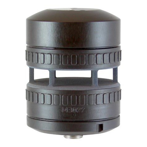
The FT205EV is the first in a new generation of lightweight ultrasonic wind sensors. It has a unique
combination of low weight (100g) and a wind speed range up to 75m/s.
The FT205EV (Evaluation Version) features a graphite and nylon composite body. The light weight of
the FT205EV together with the proven FT Acu-Res® technology make it ideal for use on aerial drones
and other weight-critical applications. It has low levels of electrical emissions and is highly resistant to
interference from vehicle systems. During development the sensor has been HALT (‘highly accelerated
life test’) tested up to 60G demonstrating its operational strength.
The FT205EV allows configurable RS422 (full-duplex), RS485 (half-duplex) or buffered UART (full-
duplex) communication outputs (3V and 5V TTL compatibility). It has been designed for easy integration
and uses a Molex CLIK-Mate connector (Molex part number: 505405-0860). The sensor is provided
with a 600mm cable (Molex part number 15135-0806).
1.2 Build Versions and Labelling
Figure 1 shows the sensor label which includes sensor serial number and relevant user information:
Figure 1: Sensor Label
The main sensor label also includes relevant user information and regulatory symbols.

Section 1 Introduction
7FT205EV Wind Sensors –User Manual
1.3 Scope of Use
The FT205 sensor has been designed primarily for wind reference use on UAV drone systems. Due to
its lack of metallic body and heater, it may not be suitable for long-term, high-reliability operation,
particularly during periods of bad weather.
No promise in part or full can be given to guarantee a sensor’s continuous operation, as circumstances
can occur that may result in the failure of the output from a sensor. Circumstances can include:
•Poor installation
•Inadequate inspection
•Power supply failures
•Poor quality electrical connections
•Lightning exposure
•Problematic environmental conditions (rain, snow, icing, cold-temperature etc.)
•Physical Damage
Higher levels of wind speed and wind direction data availability are achieved through the use of an
additional FT sensor or alternative sensor. Control strategies or algorithms, which compensate in whole
or in part, for any temporary interruption of data from individual sensors should also be applied. The
choice and implementation of such methods is entirely the Purchaser’s responsibility.
1.4 Disclaimers
There are no warranties, representations or conditions, expressed or implied of any kind given in this
manual for any design application. The Purchaser should independently undertake sufficient testing to
confirm validity and suitability of any design. The Purchaser assumes all risks and liability inconjunction
with the use of the information given.
Any warranty given by FT Technologies in respect of the Equipment is conditional upon the sensor
being handled, installed, integrated and operated in accordance within the guidelines given in this
manual.
FT Technologies can take no responsibility for the effectiveness of any sensor lightning protection
scheme implemented. The wind sensor has passed a wide range of EMC tests, but FT Technologies
does not warrant the sensor to survive lightning strikes.
Information supplied by FT Technologies Ltd. shall not be construed as permission to license to operate
under, or recommendation to infringe any existing or pending patent, patent applications or trademarks.
FT Technologies reserves the right to change product specifications, designs and functionality without
notice or obligation.
The FT and Acu-Res logos are registered trademarks of FT Technologies Ltd. Copyright © 2020 FT
Technologies Ltd. All rights reserved.
The FT205EV lightweight wind sensor comes with a limited 12-month warranty. FT will replace an
FT205EV sensor that fails within 12 months of despatch due to a failure of electronic components or
poor manufacture. This warranty does not cover failure resulting from mechanical damage or damage
from lightning.

Section 2 Functional Description
8FT205EV Wind Sensors –User Manual
2 FUNCTIONAL DESCRIPTION
2.1 Technical Performance
Sensor Performance1
Measurement Principle Acoustic Resonance (compensated against variations in
temperature, pressure and humidity)
Wind Speed Measurement
Range 0-75 m/s (0-270 km/h, 0-145.8 knots)
Resolution 0.1 m/s
Accuracy ±0.3 m/s (0-16 m/s)
±2% (16 m/s-40 m/s)
±4% (40 m/s-75 m/s)
Wind Direction Measurement
Range 0 to 360°
Sensor Accuracy 4RMS
Compass Accuracy25° RMS
Resolution 1
Acoustic Temperature Measurement3
Units Celsius, Fahrenheit or Kelvin
Resolution 0.1°
Accuracy ±2°C under the following conditions:
Wind speed between 5m/s and 60m/s
Temperature Difference < 10°C (Sensor Temp. vs Air Temp.)
Operating (air) temperature between -20°C and +60°C
Environment
Temperature Range -20° to +70°C (operational)
-40° to +85C (storage)
Humidity 0-100%
Altitude 0-4000m
Data I/O
Interface options: RS422 (full-duplex)
RS485 (half-duplex)
Buffered UART full-duplex (3V & 5V TTL compatible)
Format ASCII ‘Polled’ or ‘Continuous Update’, Polar and NMEA 0183
Data Update Rate Up to 10 measurements per second (10 Hz)
Power Requirements4
Supply Voltage 6-30 VDC range (24 VDC nominal)
Sensor Current 30mA typical
Physical
Weight 100 g
External Body Material Nylon and graphite composite
I/O Connector Molex CLIK-Mate (Molex part 505405-0860)
I/O Cable Molex CLIK-Mate (Molex 600mm part 15135-0806)
Mounting Method Surface-Mount (adaptor available for pipe-mounting)
Notes:
1.All specifications subject to change without notice. Specifications calculated with the default settings
and filters enabled
2.Requires user calibration (see Section 2.5)
3.See Sections 2.9, 6.4.2 to 6.4.4 for further details
4.See safety instruction requirements (page 5). A suitable PSU capable of providing up to 0.2A maximum
is recommended. RS422 current load is dependent on topology and resistor values, RS422 in ‘always
enabled’ mode may draw higher currents. See Section 5.2 for RS422 power requirement details

Section 2 Functional Description
9FT205EV Wind Sensors –User Manual
2.2 Wind Speed Calibration
The wind sensor is calibrated in our wind tunnels before dispatch. As the sensor has no moving parts, there is
no need to recalibrate a sensor over its lifetime as no measurement degradation will occur. The sensor’s compact
strong monolithic shape is designed to prevent accidental transducer movement or damage. FT Technologies’
calibration procedure and wind tunnels are designed to give a calibration profile that is within the accuracy limits
set in the product technical specification (see Section 2.1). Periodically the accuracy of FT’s wind tunnels are
compared with the accuracy of an independent wind tunnel to ensure that no drift has occurred.
In exceptional circumstances users may wish to apply additional calibration factors. The sensors have an option
to set a User Calibration Table, which can modify the wind sensor’s wind speed output (see Section 6.4.23).
The User Calibration Table can be programmed with up to 64 correction factors which are maintained in non-
volatile memory. When enabled, the uncorrected wind speed output is adjusted according to the stored User
Calibration Table records using linear interpolation. The adjustments are applied to wind speed readings
regardless of wind direction.
2.3 Wind Speed and Direction Filtering
It is important that the system does not rely exclusively on a single wind reading for any control decision. A single
reading may be inaccurate due to measurement error, turbulence, corruption or interference. It is recommended
that an average of wind readings is used. In addition if 100% data availability is required then a second FT sensor
or alternative wind sensors should be fitted in addition.
The sensor has optional internal filtering available. This is a digital finite impulse response (FIR) filter, which works
by calculating the moving average of a fixed number of previous readings. If filtering is being applied externally,
the sensor’s output filters can be disabled. If filtering inside the sensor is preferred, the length of the averaging for
both wind speed and direction can be independently set (See Sections 6.4.13 and 6.4.14).
Figure 2: Examples of FIR Filtering
It is recommended to use average readings to reduce the effects of air turbulence.

Section 2 Functional Description
10 FT205EV Wind Sensors –User Manual
2.4 Electronically Offsetting the Wind Direction Datum
For applications where the compass is not being used, the wind direction datum can be ‘electronically’ rotated
using the CF command. The declination angle function normally used in conjunction with the compass function
can be used to realign the datum position anywhere in the range 0-359.9°.
See Section 6.4.6 for further details.
2.5 Compass & Declination Angle Operation
The FT205EV is fitted with a solid-state electronic compass so that the wind direction can be measured relative
to magnetic North if required.
Since the FT205EV is intended for system integration it is necessary to calibrate the compass before operation
and testing is recommended. Refer to Section 6.4.6 for calibration software commands. Enabling the compass
will require approximately 5mA of additional current draw.
The wind direction can be measured either relative to magnetic North, or by programming the sensor with the
geographical location declination angle, relative to true North. The compass function can also be disabled if
required so that the wind direction is measured relative to the datum mark on the wind sensor body (as per Figure
8). The compass heading can also be read back at any time using the CF command. See Section 6.4.6 for full
details of the CF command. Both the Polar format (P) and NMEA 0183 format (N) outputs provide wind direction
data relative to North (if the compass function is enabled). The NMEA 0183 message also has a field that indicates
whether the compass module is enabled or disabled.
The effects of fixed local magnetic fields (i.e. those caused by magnetised ferrous material in proximity to the
compass) can be compensated for by performing an in situ compass calibration. It is important that the calibration
is performed with the FT205EV mounted in its final position within the host system. The calibration can only
compensate for fixed magnetic fields generated by the host system. Varying fields caused, for example, by ferrous
objects passing near the FT205EV (say by a car or truck) or high current electric circuits will not be corrected.
Should the magnetic signature of the host system change significantly (because component parts have been
added or removed), then a recalibration may be required.
2.5.1 Compass Calibration
Compass calibration should be performed away from any external stray magnetic fields. To calibrate the FT205EV
compass proceed as follows:
1) Mount the FT205EV in its final position within the host system
2) Ensure the compass is enabled (send the CFE ‘enable compass’ command, see Section 6.4.6).
3) Send the CFC ‘enable calibration’ command (see Section 6.4.6). Important: No further commands should be
sent to the FT205EV after the CFC command has been sent.
4) Slowly rotate the host system 1 complete revolution in the horizontal plane. The revolution should take between
40 and 60 seconds.
5) To complete the calibration send the CFE ‘enable compass’ command (see Section 6.4.6).
6) Store the new calibration Parameters in the compass module using the CFMS command. The save command,
for example $01,CFMS*//<cr><lf>, will save the new compass calibration parameters calculated during the
calibration process to the Interface Board Flash memory. This command is required.
2.6 Selective Filter Scheme
In addition to the averaging filter described in Section 2.3, the sensor has a feature called the Selective Filter. The
scheme allows the user to set a “validity period”, during which the sensor will exclude invalid readings from
entering the averaging filter. The output will freeze on the last previous “good” reading and only raise an error flag
once the number of bad readings exceeds the validity period. This scheme can be enabled by factory configuration
or by using the FL command (see Section 6.4.15). The filter is turned off by default to match legacy behaviour.

Section 2 Functional Description
11 FT205EV Wind Sensors –User Manual
2.7 Error Detection
The sensor has a self-checking mechanism which can detect if a reading is invalid. On very rare occasions where
an invalid reading may have been detected, this is signalled to the computer or data logger by setting an error
flag character within the wind velocity output message (see Sections 6.4.29 and 6.4.30).
When an error is detected, the error flag character is set to a value of: 1.
Note: An optional Overspeed Warning Scheme can be enabled (but is disabled by default). See Section 2.8 for
further details.
It is important that error flags are not ignored. Data associated with an error flag should not be processed as valid
wind data. The system should be capable of riding through rare periods when data may be temporarily unavailable.
If errors are ongoing (more than several seconds), a reset of the sensor should be applied (see Section 6.4.20 for
instructions on sending an RSU command).
It is recommended that errors are monitored and logged. If the frequency of errors has recently increased, then
inspection of the sensor for physical blockages may be required (see Section 4.1).
2.8 Overspeed Warning Scheme
During periods where the sensor detects wind speed beyond the rating of the sensor, the sensor will (by default)
indicate a general error flag status.
An additional overspeed warning scheme can be enabled: if an overspeed condition is detected (above the highest
speed rating), the error flag character will be set to: 2 (see Sections 6.4.29 and 6.4.30) unless a general error
condition is also detected and the flag will be set to 1.
This scheme is disabled by default.
The Overspeed Warning Scheme can be enabled by software commands (see Section 6.4.19), via the Acu Vis
PC software program or enabled in the factory before despatch.
2.9 Acoustic Temperature
The Acoustic Temperature feature takes a measurement of the ambient temperature via measurable acoustic
properties of the airflow. Sections 6.4.2 to 6.4.4 describe related software commands.
Averaged data should be used. The averaging system can be performed for 0 to 50 seconds (in increments of 10
seconds), or between 1 to 10 minutes (in increments of 1 minute).
See Section 2.1 for details regarding operating specifications. Operation with high temperature gradients
(between sensor body and ambient airflow), extreme humidity levels and low wind conditions (below 5m/s) may
result in reduced accuracy.
Caution: The acoustic temperature feature requires calibration at FT Technologies. If the sensor has had a
software upgrade to 7.5 (or above) then the data will be uncalibrated and may not comply with the official
specification.

Section 3 Mechanical & Electrical Installation
12 FT205EV Wind Sensors –User Manual
3 MECHANICAL & ELECTRICAL INSTALLATION
The FT205EV is surface-mounted and optimised for lightweight operation. The sensor uses a Molex Clik-mate
PCB connector (part 505405-0860) and is supplied with a 600mm cable (various lengths available from Molex,
600mm cable part 15135-0806). An adaptor is available and included with the sensor for pipe-mount installation.
Water resistance is achieved using a compression-fit foam gasket secured with M3 screws. The water resistance
is validated using rain tunnel tests at 2.5m of rain per hour using the supplied fixings. The sensor weighs 100g
and the external body material is 3D printed using a graphite and nylon composite.
The surface mount option uses a foam gasket and 3x M3 screws for assembly. Adaptor accessories for pipe-
mount installation are included consisting of a base unit, adaptor, 2x foam gaskets and 6x M3 screws. The pipe
section (Ø 20) is not supplied by FT due to variable customer requirements. The intended bonding scheme for
the pipe is using an epoxy adhesive. Due consideration is required for sensor placement due to the spinning
rotors.
Note: the length of the M3 screws will be dependent on the thickness of the integrated system mount.
Ensure the airflow into the sensor is not obstructed or influenced by nearby objects.
•See the safety instruction requirements on page 5
•The wind sensor installation must be properly designed to ensure the correct operation of the
sensor. This section is for guidance only. It is the responsibility of the designer and installer to
ensure that the installation and its design is fit for purpose. Please see Disclaimer Section 1.4
•Caution –Excessive length or tightening of the M3 screw may cause damage to the sensor
and threads
3.1 FT205EV Sensors
3.1.1 Mechanical & Electrical Integration
The sensor measures the effects of airflow through the sensor cavity on a resonating acoustic signal. The sensor
can be rotated to ensure alignment with a standard reference, typically Magnetic North, or the integrated compass
can calculate this automatically. For angular alignment a North datum feature is marked on the sensor with an ‘N’,
when the wind blows towards the N the sensor reports 0° (unless the compass feature is enabled).
Figure 3: The FT205EV Sensor –Mounting Examples
The mounting surface should be smooth and flat. Textured, uneven or damaged surfaces will reduce the quality
of the water ingress protection.

Section 3 Mechanical & Electrical Installation
13 FT205EV Wind Sensors –User Manual
Figure 4: FT205EV Sensor –General Sensor Views (units in mm)

Section 3 Mechanical & Electrical Installation
14 FT205EV Wind Sensors –User Manual
Figure 5: FT205EV Sensor - M3 Thread Details
Caution –Excessive length or tightening of the M3 screw may cause damage to the sensor and threads.

Section 3 Mechanical & Electrical Installation
15 FT205EV Wind Sensors –User Manual
Figure 6: FT205EV –Surface Mount Option
Caution –Excessive length or tightening of the M3 screw may cause damage to the sensor and threads.

Section 3 Mechanical & Electrical Installation
16 FT205EV Wind Sensors –User Manual
Figure 7: FT205EV –Pipe-Mounted Option

Section 3 Mechanical & Electrical Installation
17 FT205EV Wind Sensors –User Manual
When the pipe mounted version is used it will be necessary to source an appropriate length of cable.
The user selection of pipe material depends on user requirements, the FT recommended material is carbon fibre
due to its low weight and high rigidity.
Warning: The user should review all aspects of the pipe material and bonding/adhesive structure to ensure it is
compatible with health and safety requirements.
Caution –Excessive length or tightening of the M3 screw may cause damage to the sensor and threads.
Figure 8: Wind Direction Reference (Compass Disabled)

Section 3 Mechanical & Electrical Installation
18 FT205EV Wind Sensors –User Manual
3.1.2 Connector Details
The FT205EV sensor uses the Molex CLIK-Mate 8-way single-row connector (Molex part 505405-0860). The
sensor is provided with 1x 600mm cable length (50-600mm lengths are available from Molex). The 600mm cable
length has the Molex part number 151350806. The cables are fitted with the same connector on both cable ends
and corresponding pin numbering. The connector is keyed and can only be inserted in the correct orientation.
(not to scale)
Pin
RS422
(full-duplex)
RS485
(half-duplex)
Buffered
UART (full-
duplex)
Molex Wire Colour
1
Ground
Black
2
6-30 VDC
3
RS422_A RX (-)
RS485_A (-)
4
RS422_B RX (+)
RS485_B (+)
5
RS422_A TX (-)
6
RS422_B TX (+)
7
UART_RX
8
UART_TX
Figure 9: Sensor Connector (above), Cable (below) and Wiring Diagram
Care must be taken to ensure that the cable is suitable for the environment it will be used in and is adequately
rated and approved. Shielding and the use of EMI conduit may be necessary.

Section 3 Mechanical & Electrical Installation
19 FT205EV Wind Sensors –User Manual
The sensor has reverse polarity protection and is protected against miswiring of the intended cable and the power
supply rating. The cables are not shielded and EMI consideration is recommended.
3.1.3 Surge & EMI Protection
It is important to install the sensor and cabling with appropriate surge and EMI protection.
All connections from the wind sensor to any data acquisition equipment and power supply should run through
suitable Surge Protection Devices (SPD). This will suppress unwanted overvoltage transients present on the
signal or power lines. The surge suppression devices should conform to an appropriate standard (for example UL
1449 listed).
This sensor is designed for lightweight applications and does not have the enhanced surge/lightning protection of
advanced industrial sensors within the FT7 range.

Section 4 Service, Configuration & Testing
20 FT205EV Wind Sensors –User Manual
4 SERVICE, CONFIGURATION & TESTING
4.1 Inspection
The following checks are required to identify any signs of corrosion or damage on the sensor which may hinder
its performance. It is recommended that these checks be carried out annually.
Mechanical damage: Check the sensor body for signs of damage, paying attention to the seals. Also inspect for
signs of lightning damage which may appear as burns or scorch marks (or burnt smells). If damage has occurred
replace the sensor immediately. Inspect the cavity for wear, corrosion and damage. Check the gasket, fasteners
and accessories are in good condition, replace them if necessary.
Corrosion: Inspect the mounting surfaces of the sensor for signs of corrosion. If corrosion is present on any
external mounting surface, it should be removed using an abrasive cloth. Check that any seals and fasteners are
in good condition and tighten as necessary. If corrosion is present replace with parts of an appropriate finish (see
Section 3).
Interconnection cable: Inspect the condition of the cable. If it has become frayed or damaged it should be
replaced. Intermittent cable faults may not be visible and may show up as data errors. Check the intended network
component values (termination resistors etc.).
Connector protective sleeve: If cable protection is used, check for any signs of damage or degradation.
Cleaning: If any debris is present this can be removed by gently rinsing the measurement cavity surface with
distilled water using a laboratory wash bottle or similar. Please note excess water droplets can be removed by
lightly blowing or shaking the sensor.
Do not scrape or scratch the surfaces whilst rinsing. Under no circumstances should objects be inserted inside
the measurement cavity, as this can cause irreparable damage. The body of the sensor can be washed if required
Table of contents
Other FT Technologies Accessories manuals

FT Technologies
FT Technologies acures FT742-SM User manual

FT Technologies
FT Technologies acures FT722 User manual

FT Technologies
FT Technologies FT702LT/D User manual

FT Technologies
FT Technologies acures FT742-SM User manual

FT Technologies
FT Technologies FT742-D-SM User manual

FT Technologies
FT Technologies FT742 User manual