FTS G-FTL Series User manual

Owner Manual
Rotovator
G-FTL Series
IMPORTANT: Read all instructions before using this attachment
2
Congratulations on the purchase of your new attachment!
Before you get started, we have provided a helpful space to jot down a
few important details:
This manual should be considered a permanent part of this attachment
and therefore should remain with it even if the attachment is
subsequently sold.
The manufacturer continually seeks advancements in its product design
and quality. Therefore, while this manual contains the most current
product information available at the time of printing, there may be minor
discrepancies between your attachment and this manual.
If you have any questions concerning this manual, please consult your
local dealer.
Model number: G-FTL085/G-FTL105/G-FTL125/G-FTL155
Serial number:
Date of purchase:
Factory reference: FTL85/FTL105/FTL125/FTL155

3
Safety Information
Before installation/maintenance, ensure tractor and attachment are
stationary with the hydraulic lift system in a neutral position, and
the ignition key removed. Read and understand this manual fully
before operating machinery. Failure to follow all safety standards
can result in severe injury or death.
1. Regularly check condition of/service both tractor and attachment.
2. Regularly check/tighten all bolts, nuts and screws.
3. Never consume alcohol/drugs while operating machinery.
4. This attachment is for use with compact tractors only, within the
power range specied, and at the recommended speed at all times.
5. Always keep the PTO output from the tractor at 540 rpm. Reduce the
speed when working on hillsides/rough terrain.
6. Only use for the indicated purpose. Do not use to transport
personnel or livestock.
7. Always wear protective gloves, ear and eye protection and tie back
long hair. Do not wear loose clothing.
8. Always check the immediate area is clear before operating.
9. Keep spectators at a safe distance.
10. Do not run the engine in an enclosed area.
11. Do not leave the machine unattended while operating.
12. Do not touch moving parts.
13. Stop the engine if excessive vibration occurs.
14. When travelling, keep the PTO turned o.
15. Ensure the engine is switched o before any maintenance. Be aware
components can be hot after operation.
16. Pay attention to any sharp/pointed parts when servicing.
17. Always repair/replace any defective parts.
18. Do not modify the attachment in any way as this may impair the
operation and overall safety.
19. Ensure all safety guards are in place and in good condition.
20. Keep all safety signs clean and legible. Replace missing/illegible signs.
4
Safety Information (continued)
Attachment Pre-use Checks
Upon receipt of your new attachment and again within the rst 4 hours of
use (the ‘shake in’ period), we recommend the following:
1. Check/tighten all bolts, nuts and screws (and those securing blades).
2. Check the tension of any belt(s), and adjust if required.
3. Apply grease to grease points if required.
4. Check gear oil level, top-up if required but do not overll.
Be aware components can be hot after operation.
Tractor Pre-use Checks
1. Check the attachment is properly attached to the tractor. Ensure
secure pins are used on the linkage mounting pins.
2. Add extra weights to the front of the tractor (or wheel weights) if
required.
3. Check the tractor PTO turns freely, and the attachment’s PTO drive
shaft can extend suciently. Apply grease to the PTO drive shaft.
4. Frequently check the condition of the chain on the PTO drive shaft.
Keep all universal joints and protective parts in a good condition.
5. Before installing, the tractor and attachment should be stationary,
remove the key from the ignition.
6. Install and secure all safety guards, doors and covers before
operating.
7. Bystanders should leave the immediate area before connecting the
drive from the tractor.
Post-use Regular Checks
1. Check blades, belts and wearing parts. Ensure they are not damaged
and blades are secure in their mounts. Repair or replace as required.
2. Clean the attachment, and check for/clear any entangled material
around any moving parts.

5
Safety Information………………………………………………………………………..page 3-4
Specications…………………………………………………………………………………..page 6
Installation Overview…………………………………………………………………….page 7-8
Set Working Depth…………………………………………………………………………..page 9
Gearbox Maintenance…………………………………………………………………...page 10
Chain Case Oil………………………………………………………………………………..page 11
Servicing & Maintenance………………………………………………………………. page 12
Attaching & Resizing PTO Shaft……………………………………………………...page 13
Parts Diagram 1……………………………………………………………………………..page 14
Parts List for Diagram 1…………………………………………………………….page 15-18
Parts Diagram 2 & Parts List…………………………………………………………..page 19
Contents
6
Specications
The Rotovator G-FTL model is ideal for maintaining allotments and
vegetable gardens. The blades cultivate and break up soil to aid planting.
The G-FTL height is controlled by adjustable skids to 9cm. The blades are
driven by a chain. Fitted with strong safety aps to prevent debris being
thrown and a support leg for storage. Fitted with an automatic chain
tensioner. Housed in a sealed oil bath, the chain tensioner is simple and
maintenance free.
Model Width
(cm)
Depth
(cm)
Height
(cm)
Working
Width
(cm)
No. of
Blades
G-FTL85 100 60 85 85 16 12-20
hp 155
G-FTL105 120 60 85 105 20 15-22
hp 195
G-FTL125 140 60 85 125 28 20-30 210
G-FTL155 170 60 85 155 32 24-40 295

7
Before installation/maintenance, the tractor and attachment should
be stationary with the hydraulic lift system in a neutral position and
the ignition key removed.
On a at area of ground lower the three point linkage on the tractor to its
lowest position. Attach the attachment to the tractor using the three point
linkage pins and linch pins:
Installation Overview
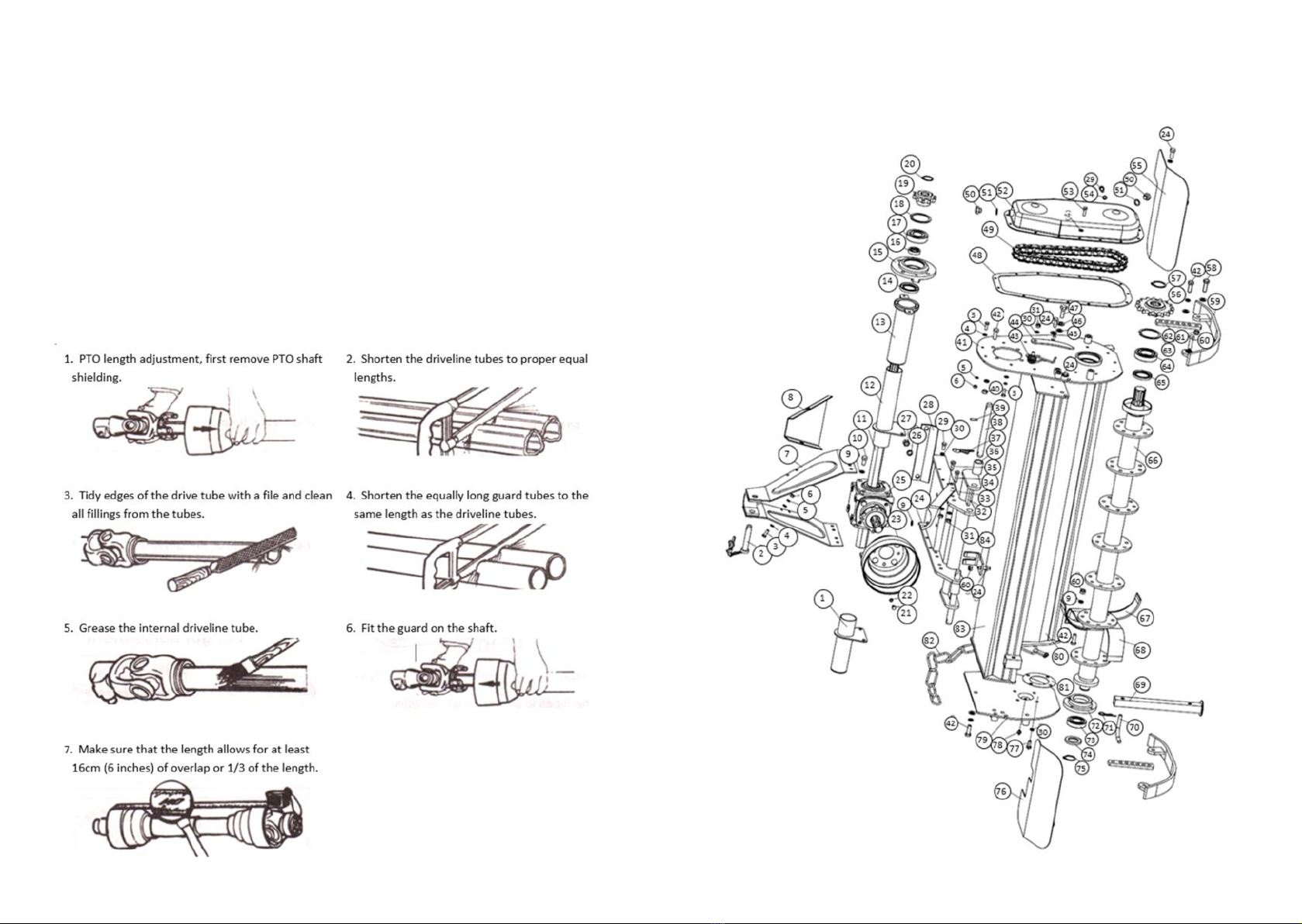
1. With the attachment on the ground, adjust the length of the top link
arm so that the attachment is level.
2. Check the clearance between the attachment skids and the blades for
the tilling depth.
3. Raise the tilling depth for drier patches of ground or heavier soil
types. To do this, raise the tractor’s hydraulic lift arms and adjust the
skids on the attachment to increase the blade tilling depth. A lower
pass can be made when the top layer of soil is broken up.
4. The working speed of the attachment should be at a walking pace of 1
to 4 mph. Heavier soil should be cultivated at a slow pace for the best
nish and to avoid any damage to the attachment.
5. Lubricate all grease points including PTO drive shaft. Attach the PTO
drive shaft and ensure locking pin is secure on both the tractor and
attachment sides. Attach the chain to a secure point on the tractor/
attachment.
6. Ensure all safety guards are in place. Always replace worn or
damaged PTO drive shafts. Operate the attachment with tractor in a
low gear range, keep the PTO output from the tractor at 540 rpm.
8
Installation Overview (Continued)
• Check the tractor's 3-point hydraulic lift system. It should operate up
and down smoothly and hold its position when set.
• The tractor should be equipped with stabiliser bars, and adjustable
sway chains or sway blocks to keep the attachment from swinging
side to side.
• Small tractors may require front counter weights to counter-balance
the weight of the attachment. We recommend the tractor has a
Rollover Protection System (ROPS) and a seat belt is used.
Operating Advice
1. Take extreme care when travelling, slow down on turns and watch out
for uneven land. Always reduce speed on slopes/corners to avoid
tipping.
2. Check the soil type and moisture level. If the ground is too dry, the
blades will struggle to cut in, and if too wet the soil will ‘ball up’ in the
rotor and blades. Typically, sandy soils can be worked better than
heavy clay or loam soil types.
3. Before starting any work, check for/remove any obstructions such as
buried pipes, rocks and stumps.
4. Set correct working depth, check the drive chain, belts and blade
condition and the tightness of all bolts, buts and screws.
5. Check the oil level in the gearbox and chain case.
6. Begin by slowly easing the rotovator into the soil: Lower the
rotovator so the blades are just o the ground, then start the PTO
drive from the tractor, slowly increasing to 540 rpm to engage the
blades. Lower the linkage slowly, to allow the blades to cut into the
soil. Move forward in a low gear, and increase speed to suit the
ground conditions. If the tractor/attachment appears to struggle, slow
the speed.
7. We recommend using two passes when tilling hard or compacted
soils. For consistency and to minimise compaction, make a second
pass at an angle to the rst.
8. Use the rear ap to maintain a level seedbed. Adjust the angle of the
ap if necessary using the chain and brackets.

9
Before installation/maintenance, the tractor and attachment should
be stationary with the hydraulic lift system in a neutral position and
the ignition key removed.
Skid Adjustment:
Raise the tilling depth for drier patches of ground or heavier soil types. To
do this, raise the tractor’s hydraulic lift arms and adjust the skids on the
attachment to increase the blade tilling depth. A lower pass can be made
when the top layer of soil is broken up.
Ensure the attachment is raised slightly o the ground, but stable and
secure when adjusting the skids.
Set Working Depth
1. Loosen and remove bolt and nut (1) on the skids on both sides of the
attachment.
2. Move the skids up or down to the desired height.
3. Align the hole on the body with the silver adjuster hole.
4. Re-insert and tighten bolt and nut (1).
1
10
Gearbox Maintenance
Gearbox Oil Level
Check oil level when the unit is cold and the machine is level. The gear oil
should be up to the level plug on the side of the gearbox. Avoid over
lling as this may cause excess pressure and oil leaks.
2
1
Gear Oil Grade 80w90 gear oil for all conditions (or equivalent)
Gearbox Oil Level Approx. 0.5 litres to level plug
First Oil Change 50 hours use
Oil Change Frequency 250 hours/yearly (whichever is rst)
Remove level plug (1) and ller/breather plug (2). The oil level should reach
level plug (1). Top-up the oil through (2) if required. Avoid over lling as
this may cause excess pressure and oil leaks. Replace and tighten both
plugs, do not over tighten ller/breather (2) as this may cause a pressure
build-up in the gearbox).
Oil Change
#1
Oil Change
#2
Oil Change
#3
Oil Change
#4
Oil Change
#5
Oil Change
#6
/ / / / / / / / / / / /
Before installation/maintenance, the tractor and attachment should
be stationary with the ignition key removed. Follow labels on any oil
and grease, always dispose of oils as instructed.

11
Chain Case Oil
Chain Case Oil Grade SAE 140 gear oil for all conditions (or equivalent)
Chain Case Oil Level Approx. 1 litre max
First Oil Change 50 hours use
Oil Change Frequency 250 hours/yearly (whichever is rst)
Before installation/maintenance, the tractor and attachment should
be stationary with the ignition key removed. Follow labels on any oil
and grease, always dispose of oils as instructed.
Chain Oil Level
Check oil level when the unit is cold & the machine is level. The oil should
be enough to just submerge the chain within the chain guard. Avoid over
lling as this may cause excess pressure and oil leaks. Avoid over
tightening the ller/breather plug.
1
2
3
Remove level plug from the lower
side of the chain guard (1). Remove
the ller/breather on top of the chain
guard section (2). The oil level should
reach level plug (1). Top-up the oil
through (2) if required.
Replace and tighten both plugs (do
not over tighten as this may cause a
pressure build-up in the chain guard).
Remove drain plug (3) when draining/
replacing oil.
Oil Change
#1
Oil Change
#2
Oil Change
#3
Oil Change
#4
Oil Change
#5
Oil Change
#6
/ / / / / / / / / / / /
12
Servicing & Maintenance
Before installation/maintenance, the tractor and attachment should
be stationary with the ignition key removed. Follow labels on any oil
and grease, always dispose of oils as instructed.
Greasing & Lubrication:
Use a clean cloth to wipe grease nipples before greasing to avoid injecting
any dirt. Press grease into each nipple 3-5 times. For best results use a
hand-held grease gun. If nipples will not take the grease, remove and clean
thoroughly. Replace or repair any broken grease points immediately. Store
all lubricants away from excessive heat, dust, moisture and contaminants.
Regularly check the condition of blades, wear gloves and take care when
handling. Replace blades if worn/broken and ensure they are balanced to
avoid excessive vibration.
Check the bearings on the blade rotor. If the oil seals are damaged, debris
may enter the bearings. Clean and replace with new bearings if required.
Run the rotovator without a load for 3-5 minutes to check bearings are
operating smoothly.
Check the condition of PTO drive shaft, immediately replace if worn or
damaged. Check the condition of the side skids, replace if worn.
Regularly check oil levels and top-up/replace when required.
Ensure the deck is clean, remove any debris from moving parts. Do not
spray water on bearings if cleaning with a high-pressure washer.
Re-paint any damaged paintwork to prevent corrosion. Store the rotovator
in a dry, level area. Support the frame if necessary.
Grease Type: Multi-purpose lithium based grease
Grease Frequency: Check every 4-8 hours (top-up if required)
Grease Points: Bearings on the blade rotor x 1 quantity
PTO drive shaft x 2 quantity

13
Attaching & Resizing PTO Shaft
Before installation/maintenance, the tractor and attachment should
be stationary with the ignition key removed. Ensure all safety guards
are in place and cover the PTO shaft when extended, ensure the
sprung locking collar slides freely and is securely in the groove on the
PTO. Always replace worn/damaged PTO shafts.
Most PTO driven attachments are supplied with a standard size PTO shaft
which often requires resizing. Firstly, attach the rotovator to the tractor
without the PTO shaft, then raise the linkage so the PTO shaft is level/
horizontal. Measure the length between the tractor PTO and the
rotovator’s shaft. If the compressed (closed) PTO shaft length exceeds the
one measured here then the driveline will need to be cut.
14
Parts Diagram 1

15
Parts List for Diagram 1
Diag.
No Ref No Part No Part Description Qty
1803400077 FTL.125.018 Shaft protection pipe (R) 1
2803440016 EF100.00.019 Suspense pin 1
3501011100 GB5783-M8X25 Bolt M8x25 17
4506010055 GB97.1-8Plain washer 8 23
5506030035 GB93-8Spring washer 8 23
6503010045 GB6170-M8 Nut M8 17
7803400032 FTL.125.014 Side A Frame weldment 1
8703340184 1GQ-125.11.110 Rear A Frame protection plate 1
9506030037 GB93-12 Spring washer 12 93
10 501011125 GB5783-M12X25 Bolt M12x25 12
11 703360193 FTL.85.130 Drive shaft 85 1
703380194 FTL.105.130 Drive shaft 105 1
703400195 FTL.125.130 Drive shaft 125 1
703430196 FTL.155.130 Drive shaft 155 1
12 803360081 FTL.85.019 Shaft protection pipe (L) 85 1
803380082 FTL.105.019 Shaft protection pipe (L) 105 1
803400083 FTL.125.019 Shaft protection pipe (L) 125 1
803420084 FTL.155.019 Shaft protection pipe (L) 155 1
13 803360090 FTL.85.020 Main protection pipe 85 1
803380091 FTL.105.020 Main protection pipe 105 1
803400092 FTL.125.020 Main protection pipe 125 1
803420093 FTL.155.020 Main protection pipe 155 1
14 510020631 CFW-45X72X10 Oil seal FB45x72x10 1
15 703400012 MZ105.128 Bearing seat 1
16 703400010 MZ105.124-1Oil seal sleeve 1
17 511024243 GB281-1307 Bearing 1307 1
18 506060191 GB893.1-80 Circlip 80 1
16
Parts List for Diagram 1 (Continued)
Diag. Ref No Part No Part Description Qty
19 703400011 MZ105.127 Top Drive chain wheel 1
20 506060315 GB894.1-32 Circlip 32 1
21 501011098 GB5783-M8X16 Bolt M8x16 5
22 506030035 GB93-8Spring washer 8 23
23 703400008 FM120.00.199 PTO shaft cover 1
24 501011126 GB5783-M12X30 Bolt M12x30 9
25 803400001 FTL.125.011 Gear box Assembly 1
26 506030038 GB93-14 Spring washer 14 2
27 503010048 GB6170-M14 Nut M14 2
28 703400177 FTL.125.112 Deck xing plate 1
29 501011111 GB5783-M10X20 Bolt M10x20 5
30 506030036 GB93-10 Spring washer 10 17
31 503010046 GB6170-M10 Nut M10 9
32 803400016 FTL.125.012 Gear box supporting plate 1
33 703320195 1GQR-105.101 Hook 1
34 501011114 GB5783-M10X35 Bolt M10x35 2
35 501011113 GB5783-M10X30 Bolt M10x30 6
36 700920096 EF100.00.106 Pin sleeve 2
37 700080010 200.56.011 Combined lock pin 2
38 703400178 FTL.125.124 Suspense pin shaft 2
39 508011537 GB879.1-6X30 Elastic cylindrical pin 6x30 2
40 503010047 GB6170-M12 Nut M12 4
41 803430002 FTL.125.025 Left supporting plate weldment 1
42 501011127 GB5783-M12X35 Bolt M12x35 68
43 703400197 FTL.125.133 Adjusting lath spring 1
44 703400180 FTL.125.134 Adjusting lath 1
45 506010057 GB97.1-12 Plain washer 12 8
46 506010058 GB97.1-14 Plain washer 14 2

17
Parts List for Diagram 1 (continued)
Diag.
No Ref No Part No Part Description Qty
47 703400182 FTL.125.136 Bolt 2
48 703400198 FTL.125.139 Gasket 1
49 703400031 FTL.125.013 Transmission chains 16Ax17 1
50 703140008 CBW-00.112 Oil plug M16x1.5x15 2
51 510015240 JB982-16 Combined oil seal 16 2
52 803400138 FTL.125.026 Chain cover 1
53 501011101 GB5783-M8X30 Bolt M8x30 2
54 510015237 JB982-10 Combined oil seal 10 1
55 803360142 FTL.85.027 Protecting handrail weldment
(LH) 85 1
803380144 FTL.105.027 Protecting handrail weldment
(LH) 105 1
803400146 FTL.125.027 Protecting handrail weldment
(LH) 125 1
803430149 FTL.155.027 Protecting handrail weldment
(LH) 155 1
56 703400199 FTL.125.140 Lower driven chain wheel 1
57 506060322 GB894.1-42 Circlip 42 1
58 501011128 GB5783-M12X40 Bolt M12x40 2
59 803400100 FTL.125.021 Active plate 2
60 501011129 GB5783-M12X45 Bolt M12x45 2
61 503010763 DIN985-M12 Lock nut M12 60
62 703400181 FTL.125.135 Adjusting plate 2
63 506060193 GB893.1-85 Circlip 85 1
64 511022615 GB276-6209 Rotor bearing 6209 1
65 510020451 CFW-50X72X10 Oil seal FB50x72x10 1
66 803360121 FTL.85.024 Shaft for blade 85 1
803380123 FTL.105.024 Shaft for blade 105 1
803400125 FTL.125.024 Shaft for blade 125 1
803430128 FTL.155.024 Shaft for blade 155 1
67 703340191 1GQ.11.127 Blade (R) 14
68 703340192 1GQ.11.128 Blade (L) 14
18
Parts List for Diagram 1 (Continued)
Diag.
No Ref No Part No Part Description Qty
69 803400047 FTL.125.016 Support stand 1
70 707180017 RB-00.101 The brance pin 1
71 703340017 ZL-25.104 R pin 1
72 703340195 1GQ-125.11.104-1Bearing seat 1
73 511022613 GB276-6207 Rotor bearing 6207 1
74 510020386 GB13871-FB-
40X62X10 Oil seal FB40x62x10 1
75 506060317 GB894.1-35 Circlip 35 1
76 803360159 FTL.85.028 Protecting handrail weldment
(RH) 85 1
803380161 FTL.105.028 Protecting handrail weldment
(RH) 105 1
803400163 FTL.125.028 Protecting handrail weldment
(RH) 125 1
803430166 FTL.155.028 Protecting handrail weldment
(RH) 155 1
77 501011112 GB5783-M10X25 Bolt M10x25 4
78 509010009 GB1152-M10X1 Grease nipple M10x1 1
79 803400040 FTL.125.015 Right supporting plate
weldment 1
80 803360103 FTL.85.022 Rear protecting plate
weldment 85 1
803380105 FTL.105.022 Rear protecting plate
weldment 105 1
803400107 FTL.125.022 Rear protecting plate
weldment 125 1
803430110 FTL.155.022 Rear protecting plate
weldment 155 1
81 703340178 1GQ-125.11.105 Bearing seat gasket 1
82 707180018 LH-6X300 Chain φ6x300mm 1
83 803360050 FTL.85.017 Deck 85 1
803380052 FTL.105.017 Deck 105 1
803400054 FTL.125.017 Deck 125 1
803430057 FTL.155.017 Deck 155 1
84 703400183 FTL.125.153 Chain xing bracket 1

19
Parts Diagram 2 & Parts List
Diag.
No Ref No Part No Part Description Qty
1703400003 FTL.125.102 Bearing seat for input
shaft 1
2703400005 FTL.125.106 Paper washer for rear
cover 1
3506060317 GB894.1-35 Circlip 35 1
4510020398 CFW-35X72X10 Oil seal 35x72x10 1
5511022613 GB276-6207 Bearing 6207 1
6511016411 GB297-30207 Bearing 30207 1
7703400006 FTL.125.107 Input shaft 1
8703400004 FTL.125.103 Bearing seat 2
9516010003 ZBT32001.3-ZG3/8-Oil plug ZG3/8-19" 1
10 703400002 FTL.125.101 Gear box case 1
11 510020390 CFW-50X68X8 Oil seal FB50x68x8 2
12 511022559 GB276-6010 Bearing 6010 2
13 703400007 FTL.125.108 Output shaft 1
Published: August 2021
This manual suits for next models
4
Table of contents
Popular Tractor Accessories manuals by other brands

Degelman
Degelman Speedblade 15 manual

Toro
Toro 04504 installation instructions

Raven
Raven AccuBoom installation manual

Hagie
Hagie UpFront STS 12 Combo Operator's manual

Original Tractor Cabs
Original Tractor Cabs 12022 Assembly instructions and parts list

Walker
Walker A44 Assembly instructions operator's manual