FuehlerSysteme FS3160 User manual

Betriebsanleitung
Operating Manual
ba_00070_FS3160_202207_R01
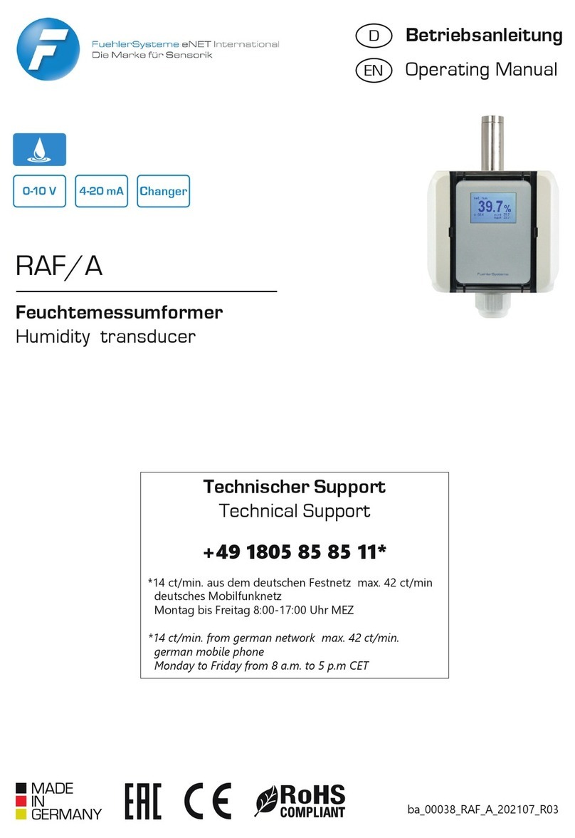
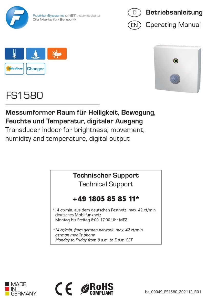
FS3160
Feuchte-/Temperaturmessumformer mit Anlegeblock,
aktiver Ausgang
Humidity / temperature transducer with contact block,
active output
Technischer Support
Technical Support
+49 1805 85 85 11*
*14 ct/min. aus dem deutschen Festnetz max. 42 ct/min
deutsches Mobilfunknetz
Montag bis Freitag 8:00-17:00 Uhr MEZ
*14 ct/min. from german network max. 42 ct/min.
german mobile phone
Monday to Friday from 8 a.m. to 5 p.m CET

2 FuehlerSysteme eNET International GmbH Röthensteig 11 90408 Nürnberg
Anwendungen
Der Feuchte –und Temperaturmessumformer mit Anle-
geblock erfasst die Temperatur und wahlweise die rela-
tive Feuchte, absolute Feuchte, das Mischungsverhältnis
oder den Taupunkt der Umgebungsluft und wandelt
diesen Messwert in ein lineares Ausgangssignal 0-10 V
bzw. 4-20 mA um.
Darüber hinaus verfügt das Messgerät über eine Heiz-
funktion zum Sensorschutz im Hochfeuchtebereich von
95...99% r.F.
Das Sensorelement ist in dem Anlegeblock montiert
und wird durch eine Sinterplatte geschützt. Durch seine
geometrische Form ist eine einfache Montage an Roh-
ren mittels Spannband möglich.
Applications
The humidity and temperature transducer with contact
block registers the temperature and, optionally, the rela-
tive humidity, absolute humidity, the mixing ratio or the
dew point of the air in the environment and converts this
measured value into a linear output signal 0-10 V re-
spectively 4-20 mA.
In addition, the measuring device has a heating function
for sensor protection in the high humidity range of
95 ... 99% r.h.
The sensor element is mounted in the contact block and
is protected by a sintered filter. Due to its geometric
shape, it can be easily mounted on pipes using a tighten-
ing strap.
Montage
Gerät öffnen: Einen geeigneten Schlitzschraubendre-
her (idealerweise Größe 3 –5,5mm breit, 0,8mm dick) in
den dafür vorgesehenen Schlitz im Deckel stecken. Mit
seitlichem Druck zur Gehäusemitte springt das Schar-
nier auf. Der Deckel kann dann geöffnet werden.
Hinweis: Bei Geräten mit Display ist eine Seite verriegelt.
Gerät schließen: Deckel schließen und fest auf das Un-
terteil andrücken. Scharnier zum Oberteil hin schließen,
bis es hörbar einrastet.
Gerät montieren: Durch die geometrische Form des
Anlegeblockes kann mittels Spannband das Gerät sehr
einfach an Rohre montiert werden.
Installation: Die elektrische Verkabelung erfolgt durch
die PG-Verschraubung/en, welche eine Zugentlastung
und Schutz vor äußeren Umwelteinflüssen ermöglicht.
Die Anschlussbelegung für Betriebsspannung (UB+,
GND) sowie den Signalausgang sind auf der Platine
aufgedruckt bzw. vermerkt.
Einbaurichtlinien: Das Gerät ist für den Ein-
satz mit einem Wetter und Strahlenschutz
ausgelegt. Ohne Wetterschutzhaube ist das
Gerät nur in Innenräumen oder dem regengeschütz-
ten Außenbereich einzusetzen. Auf Sensorschutz ist
unbedingt zu achten!
Installation
Open the device: Insert a suitable fl at-blade screwdriver
(ideally size 3 - 5.5mm wide, 0.8mm thick) into the slot
provided in the cover. The hinge opens with lateral pres-
sure towards the middle of the housing. The lid can then
be opened. Note: One side is locked on devices with a
display.
Closing the device: Close the lid and press firmly onto
the lower part. Close the hinge towards the upper part
until you hear it click into place.
Assemble the device: Due to the geometric shape of the
contact block, the device can be easily mounted on pipes
using a tensioning strap.
Installation: The electrical wiring is carried out by the
PG screw connection(s), which enables strain relief and
protection against external environmental influences. The
pin assignment for operating voltage (UB +, GND) and
the signal output are printed or noted on the circuit
board.
Installation guidelines: The device is designed
for use with weather and radiation protection.
Without a weather protection cover, the device
can only be used indoors or in rain-protected
outdoor areas.
It is essential to pay attention to sensor protection!

Support: +49 1805 85 85 11* www.fuehlersysteme.de/support/docs 3
Elektrischer Anschluss
Electrical Installation
Gerätekonfiguration
via Hardware
Offset: Der Offset kann mit dem entsprechenden
Potentiometer eingestellt werden.
Schaltschwelle: Die Relais-Schaltschwelle kann über
das Potentiometer „threshold“ eingestellt werden.
Device Settings
via Hardware
Offset: The offset can be adjusted with the corre-
sponding potentiometer.
Switching threshold: The relay switching threshold
can be set using the potentiometer „threshold“.
Messbereich Temperatur: DIP 1-2
Messbereich Feuchte: DIP 3-5
Funktion Relais: DIP 6
Measuring range temperature: DIP 1-2
Measuring range humidity: DIP 3-5
Function of relay: DIP 6

4 FuehlerSysteme eNET International GmbH Röthensteig 11 90408 Nürnberg
Gerätekonfiguration
via Displaymenü
Bei Geräten mit Display werden in der Regel zusätzliche-
Funktionen mitgeliefert, als nur die reine Anzeige von
gemessenen/berechneten Ist-Werten, Relaiszustand,
Anzeige von MIN/MAX-Werten etc.
Es sind drei Bedientasten >SET<, >DOWN<, >UP< auf
der Rückseite des Displays vorhanden. Im Display wer-
den die Tasten immer als >SET<, >DOWN<, >UP< an-
gezeigt, sobald diese eine Funktion haben, auch wenn
sich eine andere Funktion dahinter verbirgt (z.B. EXIT
statt SET). Abweichende Begriff e (z.B. >span<, >thresh<
signalisieren reine Informationsseiten.
Device Settings via
display menu
Devices with a display are usually supplied with
additional functions, such as the mere display of
measured / calculated actual values, relay status,
display of MIN/ MAX values etc.
There are three control buttons >SET<, >DOWN<,
>UP< on the back of the display. The keys are al-
ways shown in the display as >SET<, >DOWN<,
>UP< as soon as they have a function, even if there
is another function behind them (e.g. EXIT instead of
SET). Diff erent terms (e.g. >span<, >thresh< signal
pure information pages.
INFORMATION
Relais
Anzeige für welche Messgrössen das
Relais schaltet sowie der durch das Po-
tentiometer festgelegten Schaltschwelle.
Relay
Shows for which measured variable the
relay is determined and the defi ned
threshold value by the potentiometer
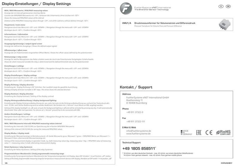
main menu > information > relay
SONSTIGE EINSTELLUNGEN / OTHER SETTINGS
Min/Max-Intervall
Einstellung des Intervalls (1/6/12/24h)
zur Speicherung der erfassten MIN/MAX
Messwerte.
min/max-interval
Setting of the Interval (1/6/12/24h) for
saving the measured MIN/MAX values.
main menu > settings > other settings > min/max interval
Relais-Hysterese
Einstellung in Prozent oder Kelvin von
der ausgewählten Skalie-
rung/Messbereich.
Relay-Hysteresis
Setting in percent or Kelvin of the selected
scaling / measuring range.
main menu > settings > other settings > relay hysteresis
DISPLAY EINSTELLUNGEN / DISPLAY SETTINGS
Display Ausrichtung
Einstellung der Display Richtung in 90°
Schritten. Der Laufpfeil zeigt die gewähl-
te Ausrichtung.
Display direction
Setting of display direction turnable in
90° steps. The arrow shows the selected
direction.
main menu > settings > display settings > display direction

Support: +49 1805 85 85 11* www.fuehlersysteme.de/support/docs 5
Display Kontrast
Kontrasteinstellung des Displays in 50
Schritten.
Display contrast
Contrast adjustment of the display in 50
steps.
main menu > settings > display settings > display contrast
Display Hintergrundbeleuchtung
Je nach Modell im Menü einstellbar.
on: dauerhaft an, off: dauerhaft aus,
auto: sobald eine Menütaste gedrückt
wird, wird die Beleuchtung für 10 Se-
kunden aktiviert.
Hinweis: Bei Geräten mit DBL-Klemme
wird die Hintergundbeleuchtung dauer-
haft aktiviert, wenn die DBL-Klemme
eine separate GND-Verbindung hat.
Display Background lighting
Depending on the model, adjustable in
the menu.
on: permanently on, off: permanently off
,auto: as soon as a menu key is pressed,
the lighting is activated for 10 seconds.
Note: For devices with a DBL terminal,
the background lighting is activated per-
manently if the DBL terminal has a sepa-
rate GND connection.
main menu > settings > display settings > display backlight
Wartung
Das Messgerät ist wartungsfrei.
Maintenance
The measuring device is maintenance-free
Technische Daten
Messbereich r.F.
0-100% r.F.
Messbereich abs. Feuchte
0-50 g/m³, 0-80 g/m³ (berechnet) per DIP-Schalter wählbar
Messbereich Misch.
0-50 g/kg, 0-80 g/kg (berechnet) per DIP-Schalter wählbar
Messbereich Taupunkt
-20...+50°C TP, -20...+80°C TP, 0...+50°C TP (berechnet) per DIP-Schalter wählbar
Messbereich Temp.
-20...+80°C
Skalierungen
-30...+70°C, -20...+80°C, 0...+50°C, 0...+100°C per DIP-Schalter wählbar
Genauigkeit Feuchte
±3% r.F. (30-70% r.F., sonst ±5% r.F., bei 20°C)
Genauigkeit Temperatur
±0,5 K
Temperaturabhängigkeit
±0,02% r.F. / K (Spannungsvariante), ±0,04% r.F. / K (Stromvariante); ±0,05°C / 10
K (Spannungsvariante), ±0,07°C / 10 K (Stromvariante)
Langzeitstabilität
±1%/Jahr
Sensor
Kombinierter elektronischer Feuchte- und Temperatursensor
Sensorschutz
Sinterfilter, Sensor im Anlegeblock montiert
Strömungsgeschwindigkeit
< 2 m/s
Spannungsversorgung analog 0-10 V
24 V AC/DC (±5%)
Spannungsversorgung analog 4-20
mA
15...36 V DC (Ubmin = 15 V + RLast*0,02A)
Stromaufnahme bei 0-10 V
Typ. 10 mA, 30 mA Peakstromaufnahme für 50 ms im Schaltmoment bei Option
Relais
Stromaufnahme bei 4-20 mA
max. 20 mA / Ausgang, 40 mA Peakstromaufnahme für 50 ms im Schaltmoment
bei Option Relais
Analogausgang 0-10 V
3-Leiteranschluss, Laststrom < 0,1 mA
Analogausgang 4-20 mA
2-Leiteranschluss (Transmitter), max. RLast(Ohm) = (+Ub - 15 V) / 0,02 A
Alarmausgang
1 x potentialfreier Wechselkontakt, 48 V, 1 A
Schalt-Hysterese Relais
2% der gewählten Skalierung (ohne Display), 0,5...5% der gewählten Skalierung
einstellbar (mit Display)
Elektrischer Anschluss
Schraubklemmen max. 1,5 mm²
Gehäuse
Polycarbonat PC UL 94 V0 mit Scharnierverschlüsse, Farbe signalweiss ähnlich RAL

6 FuehlerSysteme eNET International GmbH Röthensteig 11 90408 Nürnberg
9003
Kabeldurchführung
PG11-Verschraubung mit Zugentlastung
Anzeige
optionales LCD-Display mit Hintergrundbeleuchtung. (an/aus/auto bei 0-10 V Ver-
sion; bei 4-20 mA über DBL-Klemme)
Material
Anlegeblock: Aluminium
Abmessungen
Gehäuse: L 89 x B 80 x H 47 mm, Anlegeblock: L 25 x B 54 x H 15 mm
Schutzart
Gehäuse/Elektronik: IP65, Sensor: IP30
Schutzklasse
III
Arbeitsbereich r.F.
0...98% r.F. in schadstofffreier, nicht kondensierender Luft
Betriebstemperatur
Fühler: -20...+80°C, Elektronik: 0...+50°C
Lagertemperatur
-20...+50°C
Montage
Spannband, Bandbreite 9 mm, Spannbereich 50-110 mm, Stahl verzinkt (im Lie-
ferumfang enthalten)
Zulassungen
CE, EAC, RoHS
Technical Specifications
Measurement range r.H.
0-100% r.H.
Measurement range abs. humidity
0-50 g/m³, 0-80 g/m³ (calculated) selectable by DIP switch
Measurement range air fuel ratio
0-50 g/kg, 0-80 g/kg (calculated) selectable by DIP switch
Measurement range dew point
-20...+50°C DP, -20...+80°C DP, 0...+50°C DP (calculated) selectable by DIP switch
Measurement range temp.
-20...+80°C
Scales
-30...+70°C, -20...+80°C, 0...+50°C, 0...+100°C selectable by DIP switch
Accuracy humidity
±3% r.H. (30-70% r.H., else ±5% r.H., at 20°C)
Accuracy temperature
±0,5 K
Temperature dependency
±0,02% r.H. / K (voltage output), ±0,04% r.H. / K (current version); ±0,05°C / 10 K
(voltage version), ±0,07°C / 10 K (current output)
Long term stability
±1%/year
Sensor
Combined electronic humidity and temperature sensor
Sensor protection
sinter filter, sensor mounted inside the contact block
Flow rate
< 2 m/s
Supply voltage analog 0-10 V
24 V AC/DC (±5%)
Supply voltage analog 4-20 mA
15...36 V DC (Ubmin = 15 V + RLoad*0,02A)
Current consumption at 0-10 V
typ. 10 mA, 30 mA peak current consumption for 50 ms at switching moment at
option relay
Current consumption at 4-20 mA
max. 20 mA / output, 40 mA peak current consumption for 50 ms at switching
moment at option relay
Analogue output 0-10 V
3-wire connection, load current < 0,1 mA
Analogue output 4-20 mA
2-wire connection (transmitter), max. RLoad(Ohm) = (+Ub - 15 V) / 0,02 A
Alarm output
1 x potential-free change-over contact, 48 V, 1 A
Switching Hysteresis Relay
2% of the selected scaling (without display), 0,5...5% of the selected scaling ad-
justable (with display)
Electrical connection
screw terminals max. 1,5 mm²
Housing
Polycarbonate PC UL 94 V0 with hinge locks, color signal white similar to RAL 9003
Cable gland
PG11 high-strength cable gland with strain relief
Display
optional LCD display with backlight (on/off/auto at 0-10 V version, at 4-20 mA
version via DBL terminal)
Material
Contacting block: aluminium
Dimensions
Housing: L 89 x W 80 x H 47 mm, Contacting block: L 25 x W 54 x H 15 mm,
Protection type
Housing/electronic: IP65, Sensor: IP30
Protection class
III
Working range r.H.
0...98% r.H. in contaminant-free, non-condensing air
Working temperature
Probe: -20...+80°C, Electronic: 0...+50°C
Storage temperature
-20...+50°C
Installation
clamping band, band width 9 mm, chucking capacity 50-110 mm, galvanized steel
(in scope of delivery)
Approvals
CE, EAC, RoHS
Measurement range dew point
-20...+50°C DP, -20...+80°C DP, 0...+50°C DP (calculated) selectable by DIP switch

Support: +49 1805 85 85 11* www.fuehlersysteme.de/support/docs 7
Passendes Zubehör
Suitable accesories
SZ02/E
Spannband
Spannbereich 60-110 mm, Stahl verzinkt
Tension band
clamping range 60-110 mm, galvanized steel
SZ20/E
Steckernetzteil 24 V DC (1A) 24 W mit 1,5
m Kabel und Aderendhülsen
Plug-in power supply 24 V DC (1A) 24 W with
1.5 m cable and wire end ferrules
Masszeichnung
Measurement drawing

8 FuehlerSysteme eNET International GmbH Röthensteig 11 90408 Nürnberg
Sicherheit und
Schutzmaßnahmen
›Die Gebrauchsanleitung und weitere produktbeglei-
tende Unterlagen sorgfältig lesen und für spätere
Verwendung aufbewahren.
›Die Installation der Geräte darf nur durch Fachperso-
nalerfolgen.
Warnung
Die Geräte dürfen ausschließlich im span-
nungslosen Zustand an Sicherheitskleinspan-
nung angeschlossen werden.
›Sicherheitsvorschriften des VDE, der Länder, ihrer
Überwachungsorgane, des TÜV und der örtlichen EVU
beachten.
›Gerät nur für den angegebenen Verwendungszweck
nutzen.
›EMV-Richtlinien beachten, um Schäden und Fehler am
Gerät zu verhindern. Geschirmte Anschlussleitungen
verwenden und dabei eine Parallelverlegung zu
stromführenden Leitungen vermeiden.
›Die Funktionsweise kann bei Betrieb in der Nähe von
Geräten, welche nicht den EMV-Richtlinien entspre-
chen, negativ beeinflusst werden.
›Dieses Gerät darf nicht für sicherheitsrelevante Aufga-
ben verwendet werden, wie z.B. zur Überwachung
oder dem Schutz von Personen gegen Gefährdung
oder Verletzung, als Not-Aus-Schalter an Anlagen
oder Maschinen usw.
›Gefährdungen aller Art sind zu vermeiden.
›Bei unsachgemäßer Verwendung dieses Gerätes sind
dabei entstehende Mängel und Schäden von der Ge-
währleistung und Haftung ausgeschlossen.
›Folgeschäden, welche durch Fehler an diesem Gerät-
entstehen, sind von der Gewährleistung und Haftung
ausgeschlossen.
›Es gelten ausschließlich die technischen Daten und
Anschlussbedingungen der zum Gerät gelieferten
Montage- und Gebrauchsanleitung. Änderungen sind
im Sinne des technischen Fortschritts und der stetigen
Verbesserung unserer Produkte möglich.
›Bei Veränderungen der Geräte durch den Anwender
entfallen alle Gewährleistungsansprüche.
›Veränderungen dieser Unterlagen sind nicht gestattet.
Security and
protective measures
›Please read these instructions for use carefully and
keep them for later use.
›The installation of the devices should be done only by
qualified personnel.
Warning
The devices must be connected only in dead
state on safety-low voltage supply.
›The VDE (German Electrical Engineering Association)
security requirements of the countries and their super-
visory institutions are to be considered.
›This device is only used for the specified purpose.
›The EMC instructions are always to be observed inorder
to prevent damages and errors at the device. Shielded
cables should be used and a parallel installation of
electrical lines should be avoided.
›The operation mode can be negatively affected by the
operating close to devices which do not meet the EMC
instructions.
›This device may not be used for security-related moni-
toring, such as for monitoring or protection of individu-
als against danger or injury, as the emergency stop
switch on equipment or machinery etc.
›All kinds of threats should be avoided, whereby the
purchaser has to ensure the compliance with the con-
struction and safety regulations.
›Defects and damages resulted by improper use of this
device will not be assumed by the warranty and liabil-
ity.
›Consequential damages that result from errors of the
device will not be assumed by the warranty and liabil-
ity.
›Only the technical specifications and connection dia-
grams of the delivered device instruction manual ap-
plies. Changes in terms of technical progress and the
continuous improvement of our products are possible.
›Changes of the device by the user will not be assumed
by the warranty and liability.
FuehlerSysteme eNET International GmbH
Röthensteig 11
D-90408 Nürnberg
+49 911 37322-0
+49 911 37322-111
www.fuehlersysteme.de
info@fuehlersysteme.de
Table of contents
Other FuehlerSysteme Transducer manuals

FuehlerSysteme
FuehlerSysteme RAF/A User manual

FuehlerSysteme
FuehlerSysteme FS1580 User manual

FuehlerSysteme
FuehlerSysteme LM1/E User manual

FuehlerSysteme
FuehlerSysteme FS3060 User manual

FuehlerSysteme
FuehlerSysteme RTM1/E User manual

FuehlerSysteme
FuehlerSysteme FS1200 User manual

FuehlerSysteme
FuehlerSysteme FS1500 User manual

FuehlerSysteme
FuehlerSysteme VMU1/A User manual