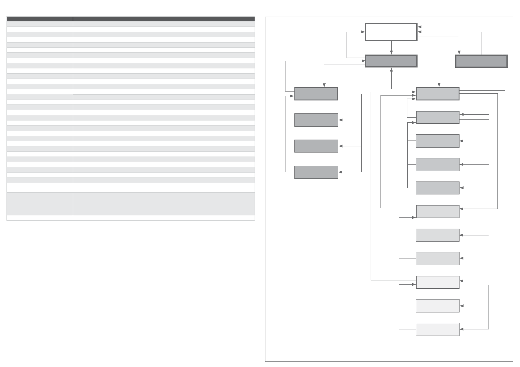
FuehlerSysteme VMU1/A User manual

Druckmessumformer für Volumenstrom und Differenzdruck
D
GB
Display-Einstellungen / Display Settings
MIN / MAX Messwerte / MIN/MAX measuring values
Shows the measured MIN/MAX values of the interval
Deletion of the MIN/MAX measuring values through >UP<, exit of the submenu without deletion through
Hauptmenü / main menu
Navigation through the menu with >UP< and >DOWN<
Bestätigen durch
Informationen / information
Navigation through the menu with >UP< and >DOWN<
Bestätigen durch
Ausgangssignalanzeige / output signal screen
Relaisanzeige / relay screen
Einstellungen / settings
Navigation through the menu with >UP< and >DOWN<
Bestätigen durch
Display Einstellungen / display settings
Navigation through the menu with >UP< and >DOWN<
Display Richtung / display direction
!
Display Kontrast / display direction
Display Hintergrundbeleuchtung / display background lighting
"#$%$&"%"'
()*'+-.012
Andere Einstellungen / settings
Navigation through the menu with >UP< and >DOWN<
MIN / MAX Messwerte Intervall/ MIN/MAX measuring values interval
Setting of the interval for saving the measured MIN/MAX values
Display Modus / display mode
$$(34'5467
(38$
Relais Hysterese / relay hysteresis
Setting of the relay hysteresis
Programmierbarer Messbereich / freely programmable measuring range
0'9(+:*%.
Technical Suppor t
+49 1805 858511
*
Kontakt / Support
Address
Phone
Fax
E-Mail & Web
info@fuehlersysteme.de
www.fuehlersysteme.de
VMU1/A
1/6
31070/20/0817

Specifications
VMU1/A
Medium
Measurement range pressure
Scales
Accuracy
Temperature dependency
Output attenuation
Linearity inaccuracy
Long term stability
Zero-point adjustment
Reaction rate
Sensor protection mounted inside housing
Running-in time
Supply voltage at 0-10 V
Supply voltage at 4-20 mA
Current consumption at 0-10 V
Current consumption at 4-20 mA
Analogue output 0-10 V
Analogue output 4-20 mA
Alarm output
Hysteresis (mechanical)
Electrical connection
Overload / Low pressure max.
Housing
Cable gland PG11 high-strength cable gland with strain relief
Display
Protection type
Protection class
Working range r.H.
Working temperature
Storage temperature
Installation
Manual zero-point adjustment
Approvals
Display-Einstellungen / Display Settings
*Abhängig vom Gerätetyp
Depending on device type
the measured value
press
>UP<
for
deletion
press
>SET<
for no
deletion
select
value with
>UP< and
>DOWN<
press >SET<
Display im
Betriebszustand
display in operation
Hauptmenü
main menu
press
>SET<
select
„information”
press >SET<
Informationen
information
select
„output”
press
>SET<
select
„relay”
press
>SET<
Ausgangssignalanzeige
output signal screen
select
„display
settings”
press >SET<
Display Einstellungen
display settings
Display Kontrast
display contrast
Display Hintergrundbel.*
display backlight
select
„DISPLAY
direction”
press >SET<
select
„DISPLAY
contrast”
press >SET<
Display Richtung
display direction
select
„DISPLAY
backlight”
press >SET<
select
„EXIT”
press >SET<
select
„EXIT”
press
>SET<
Strömungseinstellungen
flow settings
select
„flow rate”
press >SET<
select
„relay
histersis”
press >SET<
Wert Strömungsrate
flow rate value
Einstellungen
settings
select
„EXIT”
press
>SET<
MIN/MAX Messwerte
MIN/MAX measured values
press
>DOWN<
to enter
select
„settings”
press >SET<
select
„EXIT”
press
>SET<
Relaisanzeige*
relay screen
select
„offset”
press
>SET<
Offsetanzeige*
offset screen
K-Factor, output-
scaling, output unit
select
value with
>UP< and
>DOWN<
press >SET<
select
„EXIT”
press
>SET<
select
„EXIT”
press
>SET<
Andere Einstellungen
other settings
select
„min /max”
press >SET<
select
„relay
histersis”
press >SET<
Min. / Max. Intervall
min / max interval
Relais Hysterese
relay hysteresis
select
value with
>UP< and
>DOWN<
press >SET<
select
„flow settings”
press >SET<
select
„other settings”
press >SET<
select
„EXIT”
press
>SET<
2/6
31070/20/0817

Anwendungen
Applications
Technische Daten
VMU1/A
Medium Luft, nicht aggressive, nicht brennbare, nicht kondensierende Gase
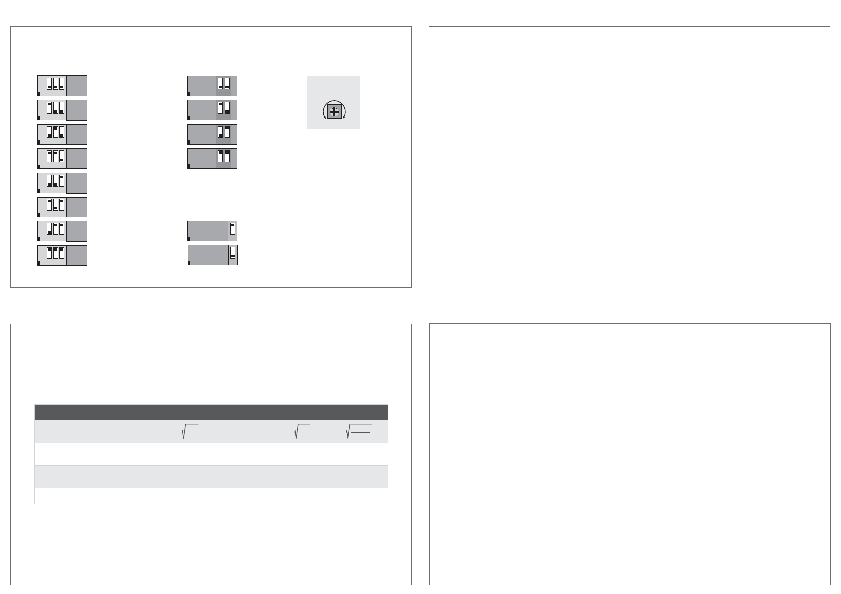
Messbereich Druck
Skalierungen
Genauigkeit
Temperaturabhängigkeit
Ausgangsdämpfung
Linearitätsfehler
Langzeitstabilität
Reaktionsgeschwindigkeit
Sensorschutz
Einlaufzeit
Spannungsversorgung bei
0-10 V
Spannungsversorgung bei
4-20 mA
Stromaufnahme bei 0-10 V
Stromaufnahme bei 4-20 mA
Analogausgang 0-10 V
Analogausgang 4-20 mA
Alarmausgang
Hysterese (mechanisch)
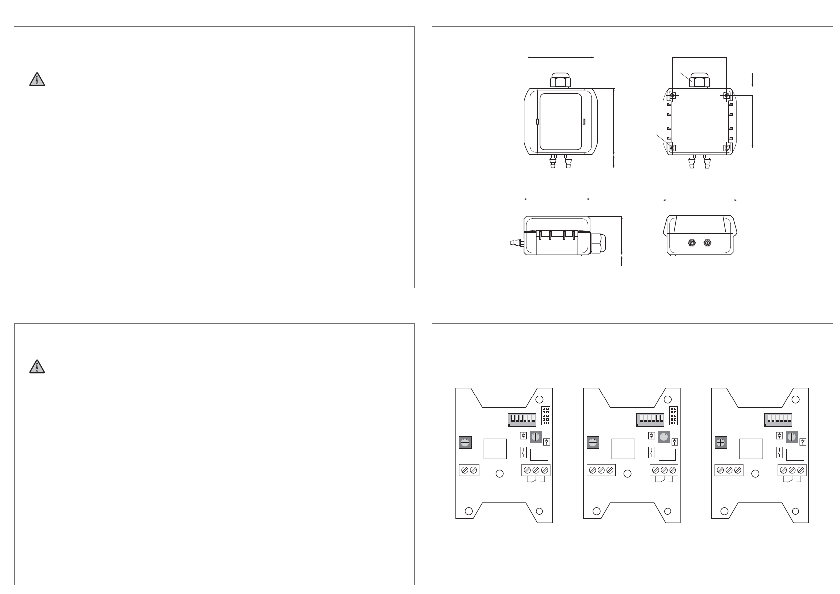
Elektrischer Anschluss
Überdruck / Unterdruck max.
Gehäuse
Kabeldurchführung PG11-Verschraubung mit Zugentlastung
Display
Schutzart
Schutzklasse
Arbeitsbereich r.F.
Betriebstemperatur
Lagertemperatur
Montage
Manueller Nullpunktabgleich
Zulassungen
VMU1/A Pressure Transducer for Volume Flow and Pressure Difference
VMU1/A Druckmessumformer für Volumenstrom und Differenzdruck
3/6
31070/20/0817

Maßzeichnung / Dimension Drawing
›
›
Warning
› -
tutions are to be considered.
›
›
› -
tions.
›
›
safety regulations.
›
›
›
›
›
Sicherheit und Schutzmaßnahmen
›
aufbewahren.
›
Warnung
-
den.
›
›
›
›
›
›
›
› -
sen.
›
Produkte möglich.
›
›
!
!
Safety and Security Precautions
P+ P-
PG11 / SW22
Ø 4,25
63
65
80
80
471
89
80
16,5
16
14,5
on
12 3 4 5 6
UB+ GND PRESS.
12 3
span
zero
threshold
Rel1
6 7 8
NC NO
on
12 3 4 5 6
UB+ GND DBL
12 3
span
zero
threshold
Rel1
6 7 8
NC NO
on
12 3 4 5 6
UB+ PRESS.
12
span
zero
threshold
Rel1
6 7 8
NC NO
I-Version I-Version / Display U-Version
VMU1/A
VMU1/A
4/6
31070/20/0817

on
4 5
Ausgangsdämpfung
Output Attenuation
0 sec
on
4 5
10 sec
on
4 5
5 sec
on
4 5
1 sec
±0%
-5% +5%
Offset Druck
Offset Pressure
0...+1000 Pa
0...+2000 Pa
0...+3000 Pa
0...+5000 Pa
on
1 2 3
on
1 2 3
on
1 2 3
on
1 2 3
Skalierungen
Scales
5000 m
3
/h (Volumenstrom / Volume flow)
6
on
1 2 3
on
1 2 3
on
1 2 3
on
1 2 3
-1000...+1000 Pa
-2000...+2000 Pa
-3000...+3000 Pa
-5000...+5000 Pa
1 2 3
Messbereich Druck
Measurement range pressure
Differenzdruck / Differential Pressure
6
1 2 3
on
on
Einstellungen
Settings
Wert
Value
Voreinstellung
default setting
Einstellbarer Bereich
adjustable range
Berechnungsformel
calculation formula QV A) QVV= K *
K-Faktor
K-Factor 75 1…3000
Ausgang-Skalierung
output scaling 5000 0…9999
Ausgabe-Einheit
output unit m³/h m³/h, m³/min, m³/sec, l/h, l/min, l/sec
P
-
Selected unit: m³/h
Selected unit: m³/h
Maximum results in: 14141 m³/h
Gerätekonfiguration / Device Configuration
VMU1/A
VMU1/A
VMU1/A
VMU1/A
5/6
31070/20/0817

P+ P- P+ P- P+ P-
Montage / InstallationMontage
3 Arten der Drucküberwachung
Installation
3 Types of Pressure Monitoring
1. Monitoring of Low Pressure
2. Monitoring of Filter
Montage / Installation
1.
;=?
2.
ÖFFNEN / OPEN SCHLIESSEN / CLOSE
1.
2.
1 2
3
3
2
1
VMU1/A
VMU1/A
VMU1/A VMU1/A
6/6
31070/20/0817
Table of contents
Other FuehlerSysteme Transducer manuals

FuehlerSysteme
FuehlerSysteme FS3060 User manual

FuehlerSysteme
FuehlerSysteme LM1/E User manual

FuehlerSysteme
FuehlerSysteme RTM1/E User manual

FuehlerSysteme
FuehlerSysteme FS3160 User manual

FuehlerSysteme
FuehlerSysteme FS1200 User manual

FuehlerSysteme
FuehlerSysteme FS1500 User manual

FuehlerSysteme
FuehlerSysteme FS1580 User manual

FuehlerSysteme
FuehlerSysteme RAF/A User manual