FuehlerSysteme FS5020 User manual

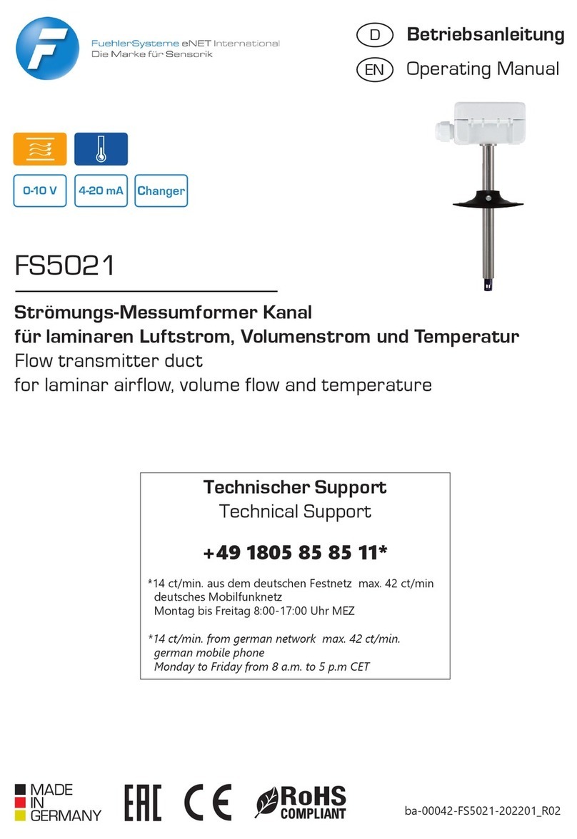
FS5020
Strömungs-Messumformer Kanal
für laminaren Luftstrom, Volumenstrom und Temperatur
Flow transmitter duct
for laminar airflow, volume flow and temperature
Betriebsanleitung
Operating Manual
Changer
0-10 V
ba-00041-FS5020-202201_R02
D
EN
Technischer Support
Technical Support
+49 1805 85 85 11*
*14 ct/min. aus dem deutschen Festnetz max. 42 ct/min
deutsches Mobilfunknetz
Montag bis Freitag 8:00-17:00 Uhr MEZ
*14 ct/min. from german network max. 42 ct/min.
german mobile phone
Monday to Friday from 8 a.m. to 5 p.m CET
4-20 mA

290408 NürnbergRöthensteig 11
FuehlerSysteme eNET International GmbH
EN
Applications
The ow transmitter detects the laminar air ow and
the temperature in air ventilation ducts. The transmitter
converts the measurement values into a linear 0-10V or
4-20mA output for further processing.
D
Anwendungen
Der Strömungs-Messumformer erfasst den laminaren
Luftstrom und die Temperatur in Lüftungskanälen.
Der Messumformer wandelt das Messergebnis zur
weiteren Verarbeitung in ein lineares Ausgangssignal
0-10 V bzw. 4-20 mA um.
EN
Installation
Open the device: Insert a suitable at-blade screw-
driver (ideally size 3 - 5.5mm wide, 0.8mm thick) into
the slot provided in the cover. The hinge opens with
lateral pressure towards the middle of the housing.
The lid can then be opened.
Note: One side is locked on devices with a display.
Closing the device: Close the lid and press rmly
onto the lower part. Close the hinge towards the up-
per part until you hear it click into place.
Assemble the device: The transmitter is attached
to the duct with the mounting ange supplied. The
immersion depth can be set with the locking screw
on the side.
D
Montage
Gerät önen: Einen geeigneten Schlitzschrauben-
dreher (idealerweise Größe 3 – 5,5mm breit, 0,8mm
dick) in den dafür vorgesehenen Schlitz im Deckel
stecken. Mit seitlichem Druck zur Gehäusemitte
springt das Scharnier auf. Der Deckel kann dann
geönet werden.
Hinweis: Bei Geräten mit Display ist eine Seite ver-
riegelt.
Gerät schließen: Deckel schließen und fest auf das
Unterteil andrücken. Scharnier zum Oberteil hin
schließen bis es hörbar einrastet.
Gerät montieren: Der Messumformer wird mit
dem mitgelieferten Montageansches am Kanal
befestigt. Die Tauchtiefe kann mit der seitlichen
Feststellschraube festgelegt werden.
5 d
h
5 d
h
d
h
Einbaubeispiel hinter einer
Kanalrichtungsänderung
Installation example behind
a change of direction
Einbaubeispiel hinter
einer Luftzufuhr
Installation example behind
an air supply
Rundkanal
Round duct
d
h
= D
B
H
Vierkantkanal
Square duct
d
h
=2xHxB
H+B
Ø D
Hydraulischer Durchmesser
Hydraulic diameter (d
h
)
)

3
Support: ((+49 1805 85 85 11* üü www.fuehlersysteme.de/support/docs
D
Gerätekonfiguration
via Hardware
Skalierung: Die Skalierung kann mittels der DIP-
Schalter 1-3 eingestellt werden (siehe Grak)
Schaltschwelle: Die Relais-Schaltschwelle kann über
das Potentiometer „threshold“ eingestellt werden.
- Bei Geräten mit Display kann auf diesem unten links
die ausgewählte Schaltschwelle und der aktuelle Re-
lais-Zustand eingesehen werden.
- Bei Geräten ohne Display und Ausgang zeigt eine
7-Segment-Anzeige den aktuellen Stand der Schalt-
schwelle an (Anzeige*10% der eingestellten Skalierung)
Einstellungen: Sollten im spannungslosen Zustand
erfolgen.
EN
Device Settings via
Hardware
Scaling: The scaling can be set using DIP switches
1-3 (see graphic)
Switching threshold: The relay switching threshold
can be set using the potentiometer „threshold“.
- For devices with a display, the selected switching
threshold and the current relay status can be viewed
at the bottom left.
- For devices without a display, a 7-segment display
shows the current status of the switching threshold
(display * 10% of the set scaling)
Settings: Should be made in a de-energized state.
D
Elektrischer Anschluss
EN
Electrical Installation
Strömungsrichtung
Flow Dircection
Bottom view
OUT1: Volumenstrom/Strömungsgeschwindigkeit
OUT2: Temperatur
OUT1: airow speed, volume ow speed
OUT2: Temperature
Relais
In-/Output
6 7 8
NC
1 2 3 4
UB+ GND OUT1 OUT2 NO
DIP FS5020
on
1 2 3
0-1 m/s
0-2 m/s
0-3 m/s
0-4 m/s
0-5 m/s
on
1 2 3
on
1 2 3
on
1 2 3
on
1 2 3
flow rate (free prog)
flow speed
1 2 3 4
on
1 2 3 4
on
Skalierung / Scaling
Schaltschwelle
signal threshold
5% 95%

490408 NürnbergRöthensteig 11
FuehlerSysteme eNET International GmbH
SONSTIGE EINSTELLUNGEN/OTHER SETTINGS
Min/Max-Intervall
Zeitliche Einstellung von 1-24 Stunden.
In dieser vergangenen Zeitspanne wird
der minimale und maximale gemessene
Wert angezeigt.
Relais-Hysterese
Einstellung in Prozent oder Kelvin von der
ausgewählten Skalierung/Messbereich.
min/max-interval
Time setting from 1-24 hours. In this
past period, the minimum and maximum
measured values are displayed.
Relay-Hysteresis
Setting in percent or Kelvin of the selected
scaling / measuring range.
main menu > settings > other settings > min/max interval
main menu > settings > other settings > relay hysteresis
INFORMATION
Ausgang
Anzeige des Messbereiches und Art des
Ausgangssignals.
Bei Geräten mit Display werden in der Regel zu-
sätzliche Funktionen mitgeliefert, als nur die reine
Anzeige von gemessenen/berechneten Ist-Werten,
Relaiszustand, Anzeige von MIN/MAX-Werten etc.
Es sind drei Bedientasten >SET<, >DOWN<, >UP<
auf der Rückseite des Displays vorhanden. Im Dis-
play werden die Tasten immer als >SET<, >DOWN<,
>UP< angezeigt, sobald diese eine Funktion haben,
auch wenn sich eine andere Funktion dahinter ver-
birgt (z.B. EXIT statt SET). Abweichende Begri e (z.B.
>span<, >thresh< signalisieren reine Informations-
seiten.
Devices with a display are usually supplied with ad-
ditional functions, such as the mere display of measu-
red / calculated actual values, relay status, display of
MIN / MAX values etc.
There are three control buttons >SET<, >DOWN<,
>UP< on the back of the display. The keys are always
shown in the display as >SET<, >DOWN<, >UP< as
soon as they have a function, even if there is another
function behind them (e.g. EXIT instead of SET).
Di erent terms (e.g. >span<, >thresh< signal pure
information pages.
Relais
Anzeige der Relaisschaltschwelle, welche
über das Potentiometer eingestellt ist.
Output
Display of the measuring range and type
of output signal.
Relay
Display of the relay switching threshold,
which is set via the potentiometer.
main menu > information > output
main menu > information > relay
D
Gerätekonfiguration
via Displaymenü
EN
Device Settings via
display menu

5
Support: ((+49 1805 85 85 11* üü www.fuehlersysteme.de/support/docs
Display Ausrichtung
Ausrichtung des Displayinhaltes in
90°-Schritten.
Hydraulischer Durchmesser
Eingabe des für Volumenstrom notwen-
digen hydraulischen Durchmesser des
Kanals (Formel siehe Montage)
Display Kontrast
Kontrasteinstellung des Displays in
50 Schritten.
Messgröße
Angezeigte Messgröße für Volumenstrom
(m³/s, m³/min, m³/h, l/s, l/min, l/h)
Messbereich
Auswahl des Messbereichs
Display direction
Alignment of the display content in
90° steps.
Hydraulic diameter
Input of the hydraulic diameter of the duct
required for the volume ow (formula see
installation)
Display contrast
Contrast adjustment of the display in
50 steps.
Measurement unit
Displayed measurement unit for volume
ow (m³/s, m³/min, m³/h, l/s, l/min, l/h)
Output Range
Selection of the measurement range
main menu > settings > display settings > display direction
main menu > settings > flow-free prog > profile
main menu > settings > display settings > display contrast
main menu > settings > flow-free prog > measurement unit
main menu > settings > flow-free prog > output range
DISPLAY-EINSTELLUNGEN/DISPLAY SETTINGS
VOLUMENSTROM-EINSTELLUNGEN/VOLUME FLOW SETTINGS
Display Hintergrundbeleuchtung
on: dauerhaft an, o : dauerhaft aus, auto:
sobald eine Menütaste gedrückt wird,
wird die Beleuchtung für eine bestimmte
Zeit aktiviert.
Display Background lighting
on: permanently on, o : permanently o ,
auto: as soon as a menu key is pressed,
the lighting is activated for a certain time.
main menu > settings > display settings > display backlight
Das Messgerät ist wartungsfrei. The measuring device is maintenance-free.
D
Wartung
EN
Maintenance

690408 NürnbergRöthensteig 11
FuehlerSysteme eNET International GmbH
Measuring principle calorimetric measuring method
Measurement range ow 0-5 m/s
Scales 0-1 m/s, 0-2 m/s, 0-3 m/s, 0-4 m/s, 0-5 m/s
Measurement range volume ow
(calculated)
0-65.000 m³/h
Measurement range temp. 0...+50°C
Accuracy ±0,3 m/s + max. ±4% FS (@ 20°C, 45% r.H., 1013 mbar), ±0,5 K (@ 20°C,
> 1 m/s)
Temperature dependency ±1% FS / 10 K
Long term stability ±1% FS/year, ±0,2 K/year
Technical Specifications
EN
Messprinzip Kalorimetrisches Messverfahren
Messbereich Strömung 0-5 m/s
Skalierungen 0-1 m/s, 0-2 m/s, 0-3 m/s, 0-4 m/s, 0-5 m/s
Messbereich Volumenstrom
(berechnet)
0-65.000 m³/h
Messbereich Temp. 0...+50°C
Genauigkeit ±0,3 m/s + max. ±4% EW (@ 20°C, 45% r.F., 1013 mbar), ±0,5 K (@ 20°C, > 1
m/s)
Temperaturabhängigkeit ±1% EW / 10 K
Langzeitstabilität ±1% EW/Jahr, ±0,2 K/Jahr
Ansprechzeit (t90) > 4 s @ 10 m/s
Einlaufzeit < 30 s bei Inbetriebnahme wg. Temperierung
Ausgangsdämpfung 5 s
Spannungsversorgung 24 V AC/DC
Stromaufnahme bei 0-10 V Ø 100 mA
Stromaufnahme bei 4-20 mA < 140 mA
Stromaufnahme bei Relais < 120 mA
Analogausgang 0-10 V 3-Leiteranschluss, min. Lastwiderstand 100 kOhm
Analogausgang 4-20 mA 3-Leiteranschluss, max. RLast(Ohm) = 300 Ohm
Alarmausgang 1 x potentialfreier Wechselkontakt, 48 V, 1 A
Schalt-Hysterese Relais 2% der gewählten Skalierung (ohne Display), 0,5...5% der gewählten Skalie-
rung einstellbar (mit Display)
Abmessungen Gehäuse: L 89 x B 80 x H 47 mm, Eintauchtiefe max.: 205 mm, Schutzrohr: Ø
16 mm
Elektrischer Anschluss Schraubklemmen max. 1,5 mm²
Gehäuse Polycarbonat PC UL 94 V0 mit Scharnierverschlüsse, Farbe signalweiss ähn-
lich RAL 9003
Kabeldurchführung PG11-Verschraubung mit Zugentlastung
Anzeige optionales LCD-Display mit Hintergrundbeleuchtung an/aus/auto
Material Schutzrohr: Edelstahl V2A
Schutzart Gehäuse/Elektronik: IP65, Sensor: IP30
Schutzklasse III
Arbeitsbereich 0,3-5 m/s, 0...98% r.F. in schadstofreier, nicht kondensierender Luft
Betriebstemperatur -20...+50°C
Lagertemperatur -20...+50°C
Montage Montageansch (im Lieferumfang enthalten)
Zulassungen CE, EAC, RoHS
Technische Daten
D

7
Support: ((+49 1805 85 85 11* üü www.fuehlersysteme.de/support/docs
Technical Specifications
Response time (t90) > 4 s @ 10 m/s
Running-in time < 30 s at initial operation because of tempering
Output attentuation 5 s
Supply voltage 24 V AC/DC
Current consumption at 0-10 V Ø 100 mA
Current consumption at 4-20 mA < 140 mA
Current consumption at relay < 120 mA
Analogue output 0-10 V 3-wire connection, min. load resistance 100 kOhm
Analogue output 4-20 mA 3-wire connection, max. RLoad(Ohm) = 300 Ohm
Alarm output 1 x potential-free change-over contact, 48 V, 1 A
Switching Hysteresis Relay 2% of the selected scaling (without display), 0,5...5% of the selected
scaling adjustable (with display)
Dimensions Housing: L 89 x W 80 x H 47 mm, Immersion depth max.: 205 mm, Pro-
tection tube: Ø 16 mm
Electrical connection screw terminals max. 1,5 mm²
Housing Polycarbonate PC UL 94 V0 with hinge locks, color signal white similar
to RAL 9003
Cable gland PG11 high-strength cable gland with strain relief
Display optional LCD display with backlight on/o/auto
Material Protection tube: stainless steel V2A
Protection type Housing/electronic: IP65, Sensor: IP30
Protection class III
Working range 0,3-5 m/s, 0...98% r.H. in contaminant-free, non-condensing air
Working temperature -20...+50°C
Storage temperature -20...+50°C
Installation mounting ange (in scope of delivery)
Approvals CE, EAC, RoHS
D
Masszeichnung
EN
Measurement drawing
Technische Daten
PG11 / SW22
Ø 4,25
63
65
80
80
47
14,5
89
80
16,5
11,5
16,2
19
28,5
60,5
86,5
5
Ø 28,5 2,5
23
58,5
205
Ø 16

890408 NürnbergRöthensteig 11
FuehlerSysteme eNET International GmbH
+49 911 37322-0
((
66+49 911 37322-111
www.fuehlersysteme.de
üü
@
FuehlerSysteme eNET International GmbH
Roethensteig 11
D-90408 Nuremberg
EN
Security and
protective measures
›Please read these instructions for use carefully and
keep them for later use.
›The installation of the devices should
be done only by qualied personnel.
Warning:
The devices must be connected only in
dead state on safety-low voltage supply.
›The VDE (German Electrical Engineering Associati-
on) security requirements of the countries and their
supervisory institutions are to be considered.
›This device is only used for the specied purpose.
›The EMC instructions are always to be observed in
order to prevent damages and errors at the device.
Shielded cables should be used and a parallel ins-
tallation of electrical lines should be avoided.
›The operation mode can be negatively aected by
the operating close to devices which do not meet
the EMC instructions.
›This device may not be used for security-related
monitoring, such as for monitoring or protection of
individuals against danger or injury, as the emer-
gency stop switch on equipment or machinery etc.
›All kinds of threats should be avoided, whereby the
purchaser has to ensure the compliance with the
construction and safety regulations.
›Defects and damages resulted by improper use of
this device will not be assumed by the warranty and
liability.
›Consequential damages that result from errors of
the device will not be assumed by the warranty and
liability.
›Only the technical specications and con-
nection diagrams of the delivered device ins-
truction manual applies. Changes in terms
of technical progress and the continuous
improvement of our products are possible.
›Changes of the device by the user will not be assu-
med by the warranty and liability.
D
Sicherheit und
Schutzmaßnahmen
› Die Gebrauchsanleitung und weitere produkt-
begleitende Unterlagen sorgfältig lesen und für
spätere Verwendung aufbewahren.
› Die Installation der Geräte darf nur durch Fach-
personal erfolgen.
Warnung
Die Geräte dürfen ausschließlich im
spannungslosen Zustand an Sicherheits-
kleinspannung angeschlossen werden.
› Sicherheitsvorschriften des VDE, der Länder, ihrer
Überwachungsorgane, des TÜV und der örtlichen
EVU beachten.
› Gerät nur für den angegebenen Verwendungs-
zweck nutzen.
› EMV-Richtlinien beachten, um Schäden und Feh-
ler am Gerät zu verhindern. Geschirmte Anschluss-
leitungen verwenden und dabei eine Parallelver-
legung zu stromführenden Leitungen vermeiden.
› Die Funktionsweise kann bei Betrieb in der Nähe
von Geräten, welche nicht den EMV-Richtlinien
entsprechen, negativ beeinusst werden.
› Dieses Gerät darf nicht für sicherheitsrelevante
Aufgaben verwendet werden, wie z.B. zur Über-
wachung oder dem Schutz von Personen gegen
Gefährdung oder Verletzung, als Not-Aus-Schal-
ter an Anlagen oder Maschinen usw.
› Gefährdungen aller Art sind zu vermeiden.
› Bei unsachgemäßer Verwendung dieses Gerätes
sind dabei entstehende Mängel und Schäden von
der Gewährleistung und Haftung ausgeschlossen.
› Folgeschäden, welche durch Fehler an diesem Ge-
rät entstehen, sind von der Gewährleistung und
Haftung ausgeschlossen.
› Es gelten ausschließlich die technischen Daten und
Anschlussbedingungen der zum Gerät gelieferten
Montage- und Gebrauchsanleitung. Änderungen
sind im Sinne des technischen Fortschritts und der
stetigen Verbesserung unserer Produkte möglich.
› Bei Veränderungen der Geräte durch den Anwen-
der entfallen alle Gewährleistungsansprüche.
› Veränderungen dieser Unterlagen sind nicht ge-
stattet.
!!
!!
Table of contents
Other FuehlerSysteme Transmitter manuals